Led
Il LED è il più semplice attuatore e può essere collegato direttamente ai connettori di Input-Output del sistema Theremino
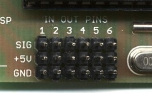
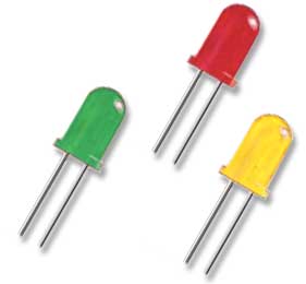
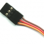
Connettere ai Pin che si trovano sui moduli Master e Servo.
Il filo rosso centrale ( V+ ) che porta i 5 volt NON deve essere connesso al LED
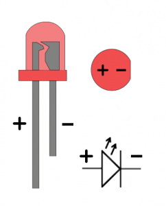
Connettere il positivo del LED sul lato “Io” del connettore (giallo sui cavi di connessione)
Connettere il negativo del LED sul lato “GND” del connettore (nero o marrone sui cavi di connessione)
Per i led si può usare qualunque pin di InOut. Configurare il pin come “DigOut” per un funzionamento “On-Off” oppure “Pwm_8” o “Pwm_16” per poter regolare la luminosità del led da zero al massimo.
I led possono essere connessi direttamente o con un resistore in serie per limitare la corrente, secondo la seguente tabella.
I moduli del sistema theremino dalla serie 3 in poi dispongono di un resistore di limitazione della corrente da 100 ohm su ogni pin di InOut per cui tutti i led possono essere collegati direttamente, se si usano moduli delle prime serie o prototipi senza serigrafia allora si devono rispettare le note seguenti:
NOTE PER I MODULI PRECEDENTI ALLA VERSIONE 3
I “Pin” di InOut sono protetti in corrente, se si superano i 15 mA, anche solo per un millisecondo, l’intera porta si spegne temporaneamente. Inoltre a causa della capacità interna dei led la corrente di spunto è sempre un poco maggiore di quella calcolata. Pertanto, se si connettono i led con caduta di tensione inferiore a 2 Volt senza resistore, può accadere di superare i 15 mA e sperimentare lampeggi inattesi di tutte le uscite che fanno capo alla stessa porta del processore. Pertanto con i moduli delle prime versioni, è sempre bene usare led con un resistore in serie da 100 ohm.
Led indicatori di prova
E’ utile disporre di led colorati saldati su connettori femmina da tre terminali con passo 2.54 che possono essere usati come jolly durante le messe a punto.
Questi piccoli indicatori di grande aiuto per la didattica dove è necessario aggiungere o togliere componenti velocemente per non perdere l’attenzione degli studenti.
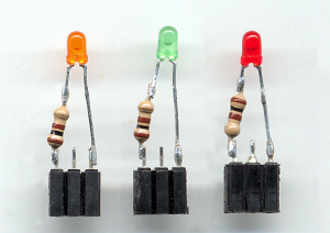
Se la luminosita’ dei led è eccessiva si può limitare la corrente con un resistore in serie come visibile qui di fianco
I nuovi moduli del sistema thremino (dalla serie 3 in poi) dispongono di un resistore interno di limitazione per cui tutti i led possono anche essere collegati direttamente, senza resistore.
Potrebbe comunque essere una buona idea collegare sempre i led con un resistore di valore molto basso, 10 ohm o meno, in modo da evidenziare il filo positivo.

Collegare sempre il resistore sul lato positivo del led (il filo più lungo) in modo da avere un riferimento quando si inseriranno questi indicatori sui connettori del sistema Theremino.
Anche inserendo i led al contrario non si danneggia nulla, semplicemente il led non si accende.
Luce bianca con led Verdi, Rossi e Blu
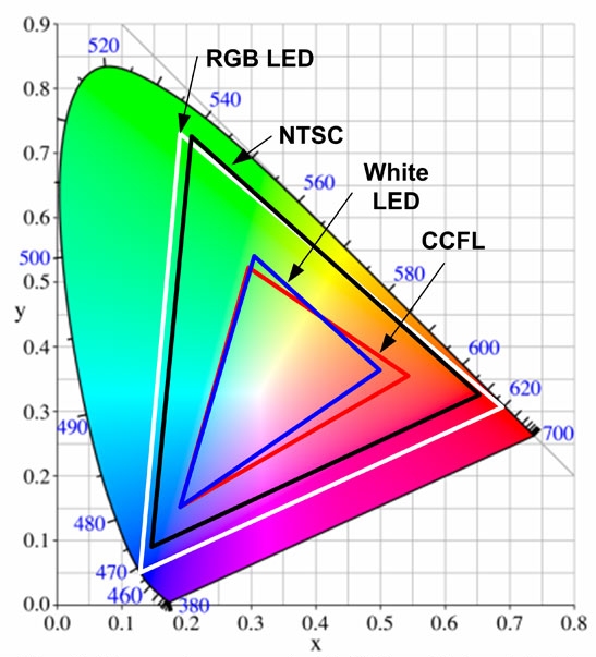
Con tre led di colore Verde, Rosso e Blu è possibile generare luce di qualunque colore, compreso il bianco e regolare l’intensità e la saturazione del colore da zero alla massima luminosità disponibile.
I tre led devono essere connessi a tre canali Pwm e controllati indipendentemente in modo manuale o con un programma host apposito.
Per ottenere un colore uniforme è preferibile usare led da 5mm con il fascio abbastanza largo e completare il tutto con uno schermo in materiale opalino o di carta bianca sottile.


Scegliere i led tra i più luminosi disponibili sul mercato e collegarli con un resistore di basso valore, come indicato all’inizio di questo documento, saranno ben visibili anche in ambienti molto luminosi.
Drivers per led a corrente costante
I led ad alta potenza devono essere alimentati con una corrente costante solitamente da 300 mA a 700 mA sono delicati e necessitano di un controllo preciso della corrente. Per alimentarli esistono in commercio molti modelli di drivers e alimentatori.
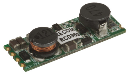
Per i particolari consultare la pagina: hardware/actuators/led-drivers
Theremino OptoRele – Un rele foto accoppiato a MOSFET
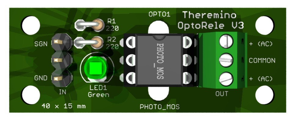
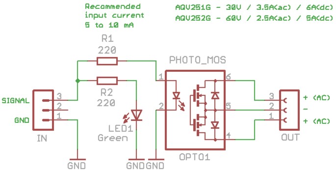
Questo è molto simile a un normale relè, ma ha caratteristiche che i relè meccanici non si sognano nemmeno. Può commutare in un millesimo di secondo per cui si può utilizzarlo anche in PWM.
A differenza dei relè meccanici questo circuito ha una durata praticamente infinita, richiede solo 5 milli Ampere di pilotaggio, ha un eccezionale isolamento ed è molto piccolo. Inoltre i PhotoMOS di ricambio sono facilmente sostituibili sullo zoccolo, anche con modelli differenti e eventualmente anche con gli economici PhotoTRIAC, che sopportano alte tensioni ma si possono usare solo in AC.
Il connettore di ingresso è a tre poli, in modo da seguire lo standard thereminico che prevede il +5Volt sul polo centrale. Ma in questo circuito il +5 Volt non è usato, quindi si possono usare due cavetti singoli Dupont per il segnale e per GND.
Se si devono pilotare più moduli vicini tra loro, si potrebbe unire il polo centrale con GND, con una goccia di stagno sul lato inferiore dello stampato. In questo modo si potrebbe portare un solo cavetto di massa (GND) e quindi usare il polo centrale per portare la massa ai moduli vicini.
Nel caso si dovesse pilotare l’ingresso con tensioni più alte di 5 Volt basterebbe aggiungere un resistore in serie al segnale.
– Per 12 Volt il resistore sarà da 1500 o 1800 ohm, 1/4 o 1/8 Watt.
– Per 24 Volt il resistore sarà da 3300, 3900 o 4700 ohm, 1/4 Watt.
Questo progetto è fortunato. Interessa ai cinesi per automatizzare le macchine avvitatrici che usano in produzione, quindi ha la precedenza su molti altri, verrà prodotto in tempo record e sarà presto disponibile su Store-Ino,
Sono disponibili anche i file STL per stampare un supporto in plastica per un modulo OptoRelè o per quattro moduli OptoRelè.
Perché usare i PhotoMOS al posto dei relè meccanici?
I relè meccanici costano dieci volte meno e sopportano correnti e tensioni maggiori, ma hanno una durata di sole duecentomila operazioni. Potrebbero sembrare tante, ma facendo i conti si possono avere delle sorprese. In un caso di esempio (una macchina avvitatrice che stiamo progettando), ci sono due relè che commutano due volte ogni sei secondi. Se la macchina fa produzione 24 ore su 24, quanto dureranno i relè? Forse qualche anno? Sbagliato, ogni settimana saranno tutti e due guasti. Dato che poi le macchine in produzione sono cinque, e presto saranno dieci, probabilmente ogni giorno ce ne sarebbero una o due in riparazione. Ecco perché, in alcuni casi, non si possono usare i relè meccanici.
Perché non usare semplicemente un Mosfet o un Darlington?
In questa stessa pagina, alcuni progetti mostrano adattatori che sopportano correnti anche maggiori e costano meno. In alcuni casi si potrebbe usarli, ma solo un PhotoMOS può dare la totale sicurezza, di isolare completamente la logica, dai disturbi elettrici causati dai grossi carichi, specie se induttivi.
Tipi di connessioni
A seconda del tipo di connessione, si ottiene un relè per AC o per DC. Con la connessione “C”, usabile solo in “DC”, si ottiene un raddoppiamento della corrente massima.
Caratteristiche dei PhotoMOS
| Sigla | Tensione massima |
Corrente_AC conness. “A” |
Corrente_DC conness. “B” |
Corrente_DC conness. “C” |
Costo (appross.) |
| AQV251G | 30 Volt | 3.5 Ampere | 4.0 Ampere | 6.0 Ampere | 6 Euro |
| AQV252G | 60 Volt | 2.5 Ampere | 3.5 Ampere | 5.0 Ampere | 5 Euro |
| PVN012APBF | 20 Volt | 4.0 Ampere | 4.5 Ampere | 6.0 Ampere | 6 Euro |
| PVN012PBF | 20 Volt | 2.5 Ampere | 3.0 Ampere | 4.5 Ampere | 5 Euro |
| VO14642A | 60 Volt | 1.0 Ampere | 1.0 Ampere | 2.0 Ampere | 2 Euro |
| VOR1142B6 | 400 Volt | 0.14 Ampere | 0.14 Ampere | 0.27 Ampere | 1.5 Euro |
Le tensioni e correnti listate in questa tabella sono il massimo sopportabile. Per stare sul sicuro è bene tenersi più bassi di almeno un 30%. Se si prevede di usare commutazioni molto frequenti (oltre i 20 Hz) è bene limitarsi ulteriormente (vedere i grafici nei data-sheet).
Se si pilotano carichi induttivi in DC (trasformatori, solenoidi e motori), ogni carico deve avere il diodo per le extra-tensioni in parallelo.
Se si pilotano carichi induttivi in AC (trasformatori, solenoidi e motori), ogni carico deve avere in parallelo, il soppressore per le extra-tensioni in silicio (Transzorb). Per ottenere una efficace protezione, il Transzorb deve avere le giuste caratteristiche di tensione e corrente.
Usare PhotoTRIAC al posto dei PhotoMOS
Limitatamente alle applicazioni in AC è possibile sostituire il PhotoMOS con un PhotoTRIAC.
I PhotoTRIAC costano poco e sopportano alte tensioni (da 400 a 800 Volt), con corrente fino a 1 Ampere (ma è bene usarli a non più di 500-700 mA).
Fare attenzione ad usare i modelli indicati. Devono essere modelli con pilotaggio di 5 mA, altrimenti non funzioneranno bene, o smetteranno di funzionare con basse temperature.
I modelli “Zero crossing” commutano solo al passaggio dello zero (quindi al massimo 100 volte al secondo). Non li si possono usare per parzializzare la potenza, ma in compenso garantiscono accensioni pulite, senza provocare extra-tensioni potenzialmente dannose.
Fare attenzione che con i PhotoTRIAC, a differenza dei PhotoMOS, si devono usare solo i due estremi (4 e 6), mentre il centrale (5) deve essere lasciato non connesso.
Caratteristiche dei PhotoTRIAC
| Sigla | Tensione massima |
Corrente massima |
Tipo di commutazione |
Costo (appross.) |
| MOC3083M | 800 Volt | 1 Ampere | Zero Crossing | 1.2 Euro |
| MOC3063M | 600 Volt | 1 Ampere | Zero Crossing | 0.8 Euro |
| MOC3043M | 400 Volt | 1 Ampere | Zero Crossing | 0.7 Euro |
| MOC3023M | 400 Volt | 1 Ampere | Istante casuale | 0.5 Euro |
Download del progetto completo
Questo file comprende il progetto in formato Eagle, le immagini 3D, gli schemi e i DataSheet dei PhotoMOS e dei PhotoTRIAC più interessanti:
Theremino_OptoRele_V3.zip
Theremino OptoTriac – Un rele fotoaccoppiato da 3 KW
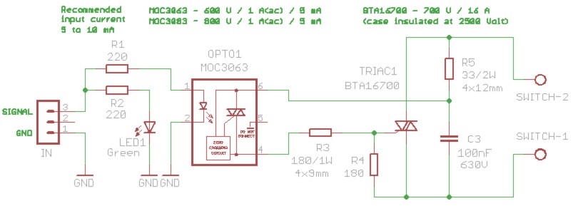
Questo circuito è molto simile a un interruttore di potenza. Può accendere e spegnere grossi carichi, come ad esempio forni e boiler. Il suo uso è però limitato alle sole applicazioni in AC (rete elettrica a 50 o 60Hz), se lo utilizzerete per interrompere correnti continue non funzionerà.
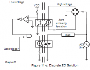
Per mezzo di un foto-accoppiatore “zero crossing”, le commutazioni avvengono sempre nel preciso istante del passaggio dello zero. Quindi le commutazioni sono pulite, i disturbi elettromagnetici completamente assenti e non si sviluppano extra-tensioni pericolose. Il metodo “zero crossing” permette anche di pilotare carichi induttivi come motori, trasformatori e grandi elettromagneti.
Il connettore di ingresso è a tre poli, in modo da seguire lo standard Thereminico che prevede il +5Volt sul polo centrale. Ma in questo circuito il +5 Volt non è usato, quindi si possono usare due cavetti singoli Dupont per il segnale e per GND.
Se si devono pilotare più moduli vicini tra loro, si potrebbe unire il polo centrale con GND, con una goccia di stagno sul lato inferiore dello stampato. In questo modo si potrebbe portare un solo cavetto di massa (GND) e quindi usare il polo centrale per portare la massa ai moduli vicini.
Questo progetto è fortunato. Interessa ai cinesi per automatizzare le macchine avvitatrici che usano in produzione, quindi ha la precedenza su molti altri, verrà prodotto in tempo record e sarà presto disponibile su Store-Ino,
Componenti
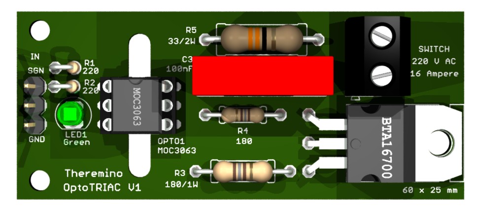
Il TRIAC deve essere assolutamente della serie BTA (o equivalenti) in modo da avere la parte metallica ben isolata (2500 Volt di isolamento). Così si potrà fissarlo a parti metalliche senza dover interporre un isolante. Che nessuno pensi di usare TRIAC non isolati e arrangiarsi con isolanti in mica. Non ci si può fidare di un isolamento casalingo con la mica, il pericolo è reale e può succedere di tutto!
Il foto accoppiatore deve essere un MOC3063 o un MOC3083. Questi due modelli si accontentano di 5 mA di pilotaggio e commutano al passaggio dello zero. Sono caratteristiche importanti e si deve rispettarle.
Aggiungere un fusibile
Progetti simili, ad esempio i regolatori di luce per le lampade a incandescenza, solitamente prevedono un fusibile sul PCB. L’idea sarebbe di proteggere il TRIAC e sarebbe una buona idea se funzionasse, ma in pratica il fusibile si interrompe dopo che il TRIAC si è già fuso.
Inoltre i portafusibili da stampato sono usabili solo fino a 6 Ampere e, per quanto esistano fusibili intercambiabili in vetro, anche da 10 Ampere e oltre, il loro uso non è a norme e si rischia che facciano contatti precari e pericolosi.
E infine, incredibile ma vero, i fusibili di qualità, che avrebbero qualche speranza di proteggere il TRIAC, costano il doppio dei TRIAC.
Quindi in questo PCB la funzione di fusibile è svolta dalla pista che va al morsetto superiore. Questa pista è più piccola delle altre e si interromperà in caso di emergenza. Con “emergenza” non si intende di proteggere il TRIAC, ma di evitare di fondere i cavi dell’impianto elettrico o di far scattare l’automatico.
Se si pensa di lavorare a 16 Ampere (e anche oltre con TRIAC più grandi), si dovrebbero rinforzare le due piste che vanno dal morsetto a vite fino al TRIAC. Fino a 10 Ampere basta incrementare lo spessore delle piste, usando lo stagno e il saldatore, oltre i 10 Ampere si dovrebbe aggiungere un filo di rame nudo, saldato sulle piste.
Prevedere sempre un piccolo tratto di pista, senza stagnatura e senza filo di rame, con la funzione di fusibile di emergenza. Oppure aggiungere un porta-fusibile da pannello.
Mantenere freddo il TRIAC
Fino a un centinaio di Watt non ci sono problemi, il TRIAC potrebbe anche stare senza dissipatore. Ma per arrivare a 3 KW e oltre, un dissipatore è assolutamente necessario. La soluzione giusta per dissipare bene non è inventarsi un piccolo dissipatore (per quanto alettato), ma portare via il calore con una staffa di alluminio e dissiparlo su una grossa superficie metallica, probabilmente il contenitore stesso.
Una buona soluzione è una “L” di alluminio, larga come il metallo del TRIAC, e spessa 2 o 3 millimetri. Con questa “L” ci si allontana dalle parti sotto tensione e il fissaggio diventa facile. La parte verticale della “L” potrà essere avvitata a una grande parete metallica, che fornirà la dissipazione richiesta.
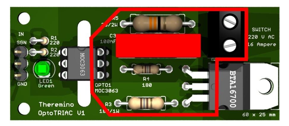
Area pericolosa
Fare molta attenzione! L’area contornata con la linea rossa è collegata alla rete elettrica. Pertanto si consiglia questo progetto solo a chi conosce bene l’elettronica.
Per evitare pericoli è bene usare un contenitore isolante. La parte metallica del TRIAC è isolata internamente, e quindi può essere avvitata direttamente su un dissipatore di allumino. Però si deve fare attenzione a costruire bene il dissipatore, la sua forma deve essere precisa in modo da non avvicinarsi troppo alle parti metalliche sotto tensione.
Download del progetto completo
Questo file comprende il progetto in formato Eagle, le immagini 3D, gli schemi e i DataSheet dei PhotoTRIAC e dei TRIAC più interessanti:
Theremino_OptoTriac_V1.zip
Theremino OptoMos – Un MOS di potenza fotoaccoppiato
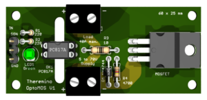
Questo circuito è un interruttore di potenza per correnti continue fino a 40 ampere, con tensioni fino a 70 volt (a seconda del triac che si monta e del tipo di dissipatore).
Il funzionamento è simile ai precedenti OptoRelè e OptoTriac, ma a differenza di essi lo si può usare solo con tensione continua. Quindi sia sul connettore di alimentazione che sul connettore di uscita si deve rigorosamente rispettare la polarità. In compenso questo circuito può interrompere correnti notevolmente maggiori e può anche essere utilizzato in PWM, cosa che l’OptoTriac non può fare.
La presenza di un foto-accoppiatore permette di interrompere la corrente in qualunque punto, senza preoccuparsi della tensione che c’è in quel punto rispetto alla massa. Inoltre mantenere isolata la parte di commutazione da quella di pilotaggio elimina il pericolo di inviare disturbi verso la linea USB.
Il connettore di ingresso è a tre poli, in modo da seguire lo standard Thereminico che prevede il +5Volt sul polo centrale. Ma in questo circuito il +5 Volt non è usato, quindi si possono usare due cavetti singoli Dupont per il segnale e per GND.
Se si devono pilotare più moduli vicini tra loro, si potrebbe unire il polo centrale con GND, con una goccia di stagno sul lato inferiore dello stampato. In questo modo si potrebbe portare un solo cavetto di massa (GND) e quindi usare il polo centrale per portare la massa ai moduli vicini.
Questo progetto è fortunato. Interessa ai cinesi per automatizzare le macchine avvitatrici che usano in produzione, quindi ha la precedenza su molti altri, verrà prodotto in tempo record e sarà presto disponibile su Store-Ino,
Componenti
Il MOSFET può essere uno dei seguenti:
- TK46A08N1,S4X – 80V / 46A / 6.9 milli-ohm / 0.8 Euro
- TK58A06N1,S4X – 60V / 58A / 4.4 milli-ohm / 0.9 Euro
- TK72A08N1,S4X – 80V / 72A / 3.7 milli-ohm / 1.6 Euro
- IRFP054NPBF – 55V / 72A / 12 milli-ohm / 1.7 Euro
I prezzi dei MOSFET sono approssimativi e sono da intendersi per un pezzo se se ne comprano almeno dieci per volta su Mouser.
Questi MOSFET hanno il contenitore in plastica per cui si può fissarli a parti metalliche senza dover interporre un isolante.
Per gli altri componenti consultare lo schema elettrico e fare attenzione alle note sui resistori da utilizzare a seconda della tensione di alimentazione.
Una volta scaricato il file ZIP nella cartella DataSheets troverete la documentazione sui MOSFET e sui foto-accoppiatori, nonché i collegamenti alle pagine di Mouser per acquistarli.
Mantenere freddo il MOSFET
Fino a circa 5 ampere non ci sono problemi, il MOSFET potrebbe anche stare senza dissipatore. Ma per arrivare a 10 ampere e oltre, un dissipatore è assolutamente necessario. La soluzione giusta per dissipare bene non è inventarsi un piccolo dissipatore (per quanto alettato), ma portare via il calore con una staffa di alluminio e dissiparlo su una grossa superficie metallica, probabilmente il contenitore stesso.
Una buona soluzione è una “L” di alluminio, larga come il metallo del MOSFET, e spessa 2 o 3 millimetri. Con questa “L” ci si allontana dalle parti sotto tensione e il fissaggio diventa facile. La parte verticale della “L” potrà essere avvitata a una grande parete metallica, che fornirà la dissipazione richiesta.
Con alte correnti dovrete assolutamente fare delle prove e controllare per i primi trenta minuti, con un termometro a infrarossi, che la temperatura non superi i 90 gradi in nessun punto. Oltre i 25 ampere potrebbero esserci problemi anche con i connettori e con le piste del circuito stampato.
Nel caso di pilotaggio con segnale PWM la dissipazione potrebbe aumentare a causa delle commutazioni. Il massimo della temperatura lo si ottiene regolando il PWM a metà e utilizzando frequenze alte. Per cui si dovrebbero utilizzare frequenze basse di PWM, cioè 1 kHz per i motori e anche meno per dispositivi riscaldanti. Per dispositivi molto lenti, come i forni o i pannelli delle stampanti 3D, si potrebbe anche non utilizzare il PWM. ma accendere e spegnere direttamente dal software. In questo caso si imposterebbe il Pin di uscita come DigOut e il software dovrebbe essere scritto in modo da accendere e spegnere abbastanza velocemente (una decina di volte al secondo)
Download del progetto completo
Questo file comprende il progetto in formato Eagle, le immagini 3D, gli schemi e i DataSheet dei MOS:
Theremino_OptoMOS_V1.zip
Driver on-off per alta corrente
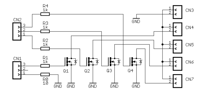
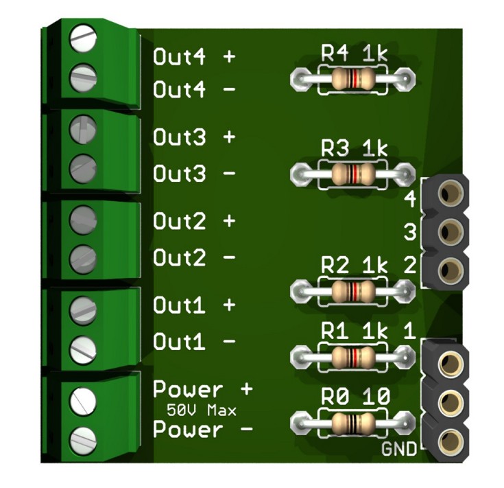
Questo adattatore può alimentare relè, motori in continua, elettrovalvole, lampadine a bassa tensione, strisce di LED e qualunque altro attuatore che necessiti di una tensione continua da qualche volt fino a 60 Volt con correnti fino a 2 Ampere.
Il connettore CN1 si collega ad un qualunque PIN di InOut del sistema Theremino e fornisce il collegamento di massa e il segnale del primo canale. Il connettore CN2 si collega ai pin di segnale di tre InOut adiacenti e fornisce i segnali per gli altri tre canali. In questo modo si collegano quattro canali con due sole prolunghe standard.
Il connettore CN3 si collega ad un alimentatore in continua, solitamente da 12 o da 24 Volt (o da 1Volt a 55Volt o anche di più se si usano mosfet adatti) Fare attenzione che il negativo dell’alimentatore deve essere collegato sul lato GND
I connettori CN4, CN5, CN6 e CN7 sono le uscite per gli attuatori. Fare attenzione che gran parte degli attuatori devono essere connessi con la giusta polarità.
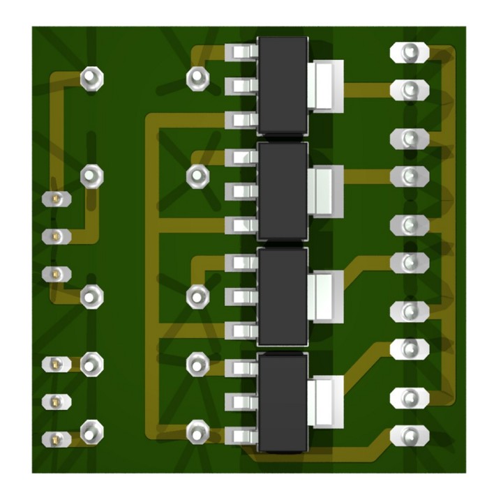
Usando la disposizione di componenti qui mostrata è possibile realizzare questo adattatore molto facilmente anche su un ritaglio di basetta millefori. I mosfet di tipo a montaggio superficiale hanno una distanza tra i piedini compatibile con la distanza standard di 2.54 mm tra i fori.
I connettori e i resistori stanno sul lato superiore senza rame, i mosfet si saldano sul lato opposto. Con quattro pezzi di filo recuperati dai resistori si fanno i collegamenti e in pochi minuti l’adattatore è finito.
Per i mosfet consigliamo:
BSP318S        60V  2.6A   30nS  0.090ohm   0.6 Euro
BUK9840-55     55V  10A    50nS  0.040ohm   0.4 Euro
PMT29EN        30V  6A     30nS  0.024ohm   0.2 Euro
BUK78150-55A   55V  5.5A   20nS  0.150ohm   0.2 Euro
(prezzi approssimativi, dal catalogo Farnell, senza iva)
Questi mosfet contengono anche un diodo di protezione e sono praticamente indistruttibili, collegandoli con i resistori si evita che disturbi elettrici ed extra-tensioni possano ritornare verso il PC (non si romperebbe nulla anche senza ma altri sensori molto sensibili potrebbero venire disturbati)
Esistono anche altri mosfet simili a quelli da noi consigliati ma si deve fare attenzione che devono essere con tensione di soglia Gate-Source molto bassa (meno di 3 volt) altrimenti non chiuderanno bene e scalderanno con forti correnti.
Il progetto completo in formato Eagle può essere scaricato da qui:
Adapter_OnOff
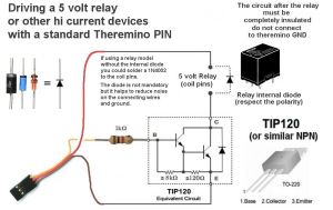
Semplice pilotaggio di un relè
Fare click sulla immagine per ingrandire.
Questo circuito può essere costruito “per aria”, con l’aiuto di qualche pezzetto di tubicino di plastica, o guaina termo-restringente, per isolare i punti critici.
– – – – – –
La corrente di uscita dei Pin del sistema Theremino (massimo una decina di milli ampere), è sufficiente per pilotare led, foto-accoppiatori e relè a stato solido. Ma per pilotare relè meccanici, o altri utilizzatori, come i motori in continua, sono necessarie correnti più alte.
La massima corrente pilotabile con questo circuito è la massima corrente fornita della USB (quasi 500 mA con le USB 1 e 2, e quasi 3 Ampere con la USB 3).
Fino a che le correnti sono piccole (50 o 100 mA), il diodo di protezione sul transistor è sufficiente. Ma nel caso di grossi carichi induttivi (bobine di attrazione meccanica, grossi relè o grossi motori) sarebbe meglio aggiungere un diodo 1N40xx in parallelo al rele (o motore). Anche in questo caso, con la fascetta verso l’alto (verso il +5 Volt).
Per correnti basse (fino ai 50 o 100 mA dei piccoli rele) si potrebbero usare transistor piccoli (BC237, BC337, BC547, BC548 e simili…). Con questi transistor si dovrebbe aggiungere un diodo di protezione sulla bobina del relè, con la fascetta dal lato positivo. Come diodo di protezione possono andare bene gli 1N4148 o simili.
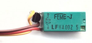
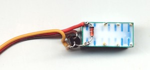
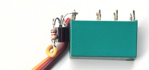
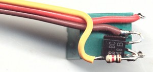
Un esempio con un piccolo rele FEME
Questi piccoli relè assorbono solo 50 mA a 5 Volt. Abbiamo verificato in pratica che qualunque piccolo transistor NPN può andare bene. Per cui si può costruire un circuito piccolissimo. Per fissare il cavetto e isolare i componenti, si possono usare due gocce di colla a caldo.
In queste immagini il transistor è un BC548, il diodo un 1N4148 e il resistore è da 1K (un ottavo di watt). Fare click sulle immagini per ingrandirle.
Moduli Relè commerciali
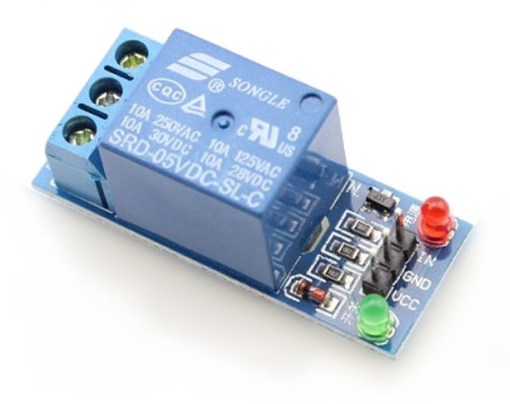
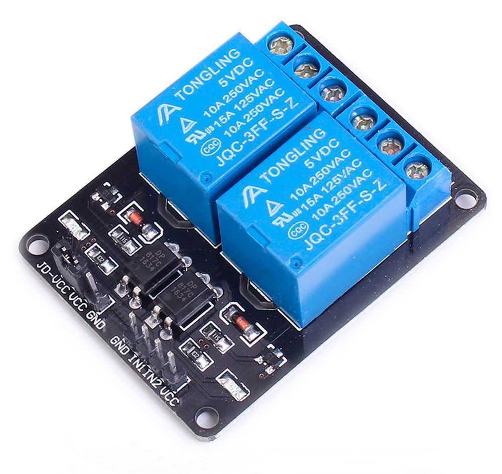
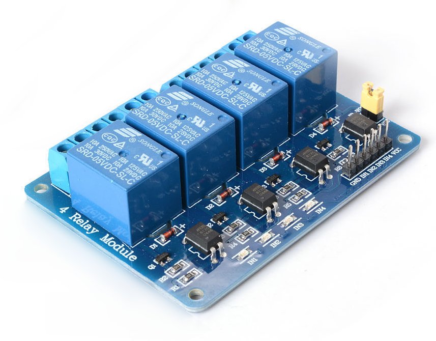
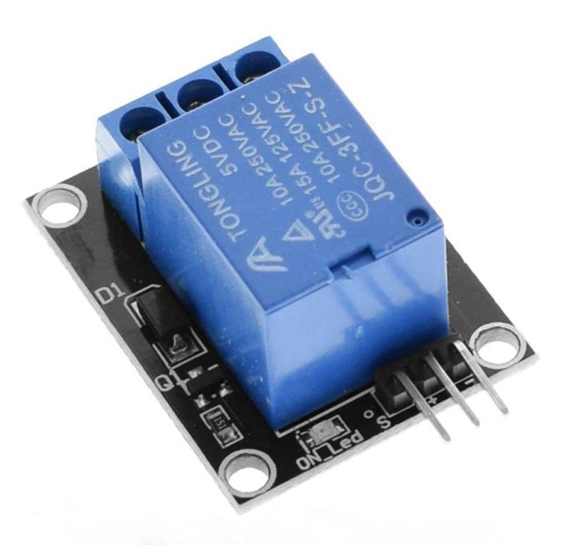
Su eBay si possono acquistare moduli con Relè meccanici completi di l’elettronica per controllarli. Fare attenzione che siano adatti ad una alimentazione da 5 volt e che siano pilotabili con un segnale TTL, cioè che gli bastino i 3.3 volt del segnale in uscita dai Pin del Master. Quasi tutti i modelli dovrebbero accettare un segnale TTL, quindi anche da 2.5 o 3 volt in su, ma alcuni potrebbero volere 5 volt e non riuscire ad accendersi con soli 3.3 volt.
I relè meccanici sopportano più corrente e più tensione dei relè a stato solido e sono anche più economici. Gli unici loro punti di inferiorità sono la durata (da 10 mila a 100 mila commutazioni), e la lentezza di commutazione (molte decine di millisecondi). Per cui non li si possono pilotare con segnali Pwm (ma sempre con Pin configurati come DigOut).
Esistono moduli da 1, 2, 4 o 8 relè, ecco alcuni esempi:
Fare click sulle immagini per ingrandirle.
E’ importante notare che i connettori di gran parte di questi moduli non hanno la stessa disposizione dei Pin del Master. In genere hanno la massa in mezzo, mentre il Master ha la massa da un lato e il 5 volt in mezzo. Questo vuol dire che si dovranno incrociare i tre fili, e fare molta attenzione a collegarli giusti.
Tra tutti gli esempi qui illustrati solo quest’ultimo ha la stessa disposizione dei Pin del Master, cioè Segnale / Positivo (+5) / Negativo (GND).
Driver generico per forti carichi
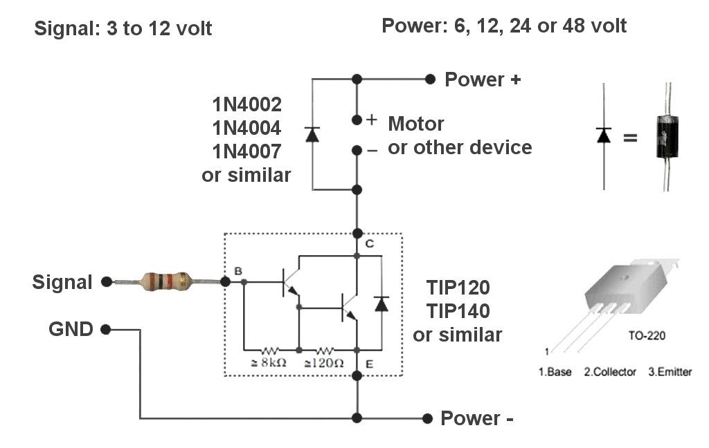
A volte può essere necessario pilotare carichi con tensioni fino a 50 volt (e oltre) e con correnti fino a una decina di ampere. In questi casi i dispositivi più robusti e più facilmente reperibili sono i transistor di tipo Darlington. Un Darlington è composto da due transistor nello stesso involucro e ha le seguenti caratteristiche:
- Alto guadagno in corrente (lo si pilota con pochi milliampere e controlla molti ampere).
- Alta corrente sopportabile (fino ad alcuni ampere senza dissipatore, e fino a decine di ampere, se ben raffreddato, e a seconda dei modelli).
- Alta tensione sopportabile (quasi tutti sopportano almeno 80 volt e alcuni modelli arrivano anche fino a 120 volt).
Note per il circuito:
- Il segnale di comando arriva solitamente da un Pin del modulo Master, configurato come DigOut (ricordarsi di collegare anche il filo di massa GND).
- Se il carico lo sopporta, si può configurare il Pin come Pwm (o FastPwm) e regolare la corrente media che si fornisce al carico. Il Pwm accende e spegne velocemente il carico. Per cui non si ottiene una vera regolazione lineare della corrente. Comunque in alcuni casi, ad esempio Led o motori, si ottiene una regolazione abbastanza buona.
- Nei punti Power+ e Power- si deve collegare un alimentatore con tensione adeguata al carico da alimentare. L’alimentatore deve anche poter fornire una corrente massima sufficiente (che sia almeno del 20% o 30% maggiore di quella che si invia normalmente al carico).
- Nei punti + e – Motor, si può collegare qualunque utilizzatore che lavori con corrente continua e tensioni da 5 a 50 volt (e anche più se si utilizza un transistor che sopporta alte tensioni). Ad esempio motori, molti Led in serie, grossi relè, lampadine a incandescenza, resistenze riscaldanti, ecc…
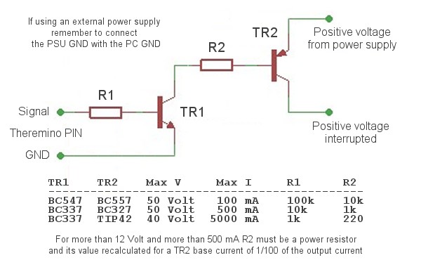
Interruttore di alimentazione positiva
Questo semplice circuito può essere utile in molti casi per alimentare piccoli motori, relè e apparecchiature elettroniche in genere. Se il carico è induttivo, come ad esempio i relè, si deve mettere in parallelo al carico un diodo 1N4002 (va bene anche un 4007).
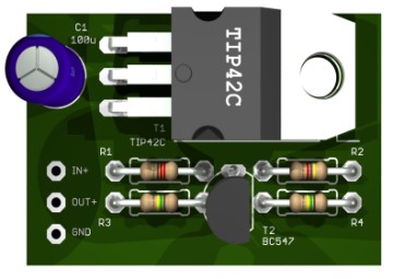
Si possono interrompere tensioni fino a 50 Volt e correnti fino a molti Ampere. Se si fornisce abbastanza corrente alla base di T2 (almeno un centesimo della corrente massima) allora la caduta di tensione sarà molto bassa (sotto ai 100 mV).
Il vantaggio di interrompere la alimentazione positiva è di poter mantenere in comune le masse del PC (e quindi del sistema Theremino) e le masse del circuito alimentato.
In tutti i casi (anche con il circuito a Mosfet) la massa del PC e quella dell’alimentatore esterno devono essere collegate tra loro. Si può usare un filo giallo-verde, che unisce il morsetto GND dell’alimentatore esterno, con un punto robusto di massa sul PC. Un buon punto dove collegare il filo dal lato PC è la massa delle prese USB o la massa del cavo USB che va al master.
Rele Switcher
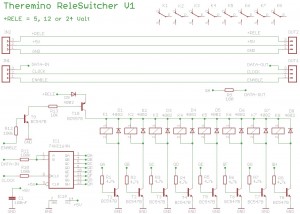
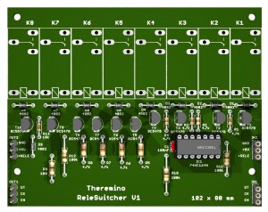
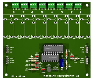
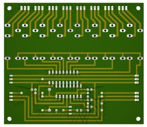
Questo modulo pilota otto relè (o altri dispositivi a bassa tensione). Per aumentare il numero di canali, si aggiungono altri moduli uguali. Si collega ogni modulo alla uscita del modulo precedente. Tutti i canali sono indipendenti e il numero di canali è praticamente illimitato. Il circuito stampato è progettato con tutti i componenti a passo 2.54 e senza sovrapposizioni di piste, per cui si può montarlo velocemente su una basetta millefori a una sola faccia (meno costosa).
Si parte da tre soli Pin, configurati come DigOut e si collega questo modulo alla fine di un lungo cavo schermato, con quattro fili interni (ma si potrebbe anche usare un cavo non schermato per citofoni). Il cavo può essere lungo molte centinaia di metri. Un solo modulo Master potrebbe pilotare due di queste linee, raddoppiando la velocità di esecuzione.
Tensione di alimentazione dei relè
La alimentazione dei relè può essere lo stesso 5 Volt, in arrivo dall’USB e dal cavo di collegamento, ma si deve fare attenzione che:
– I relè devono avere la bobina da 5 Volt e possibilmente a bassa corrente.
– Il cavo di collegamento non deve provocare una caduta di tensione maggiore di un volt.
– La corrente di tutti i relè accesi non deve superare i 500 mA della porta USB.
Con il 5 Volt si dovrebbero poter pilotare circa 16 rele, con un cavo per citofoni lungo qualche decina di metri (per la alimentazione i cavi da citofono hanno due fili più grandi). Meglio comunque fare i conti, con la corrente dei relè e la resistenza del cavo.
Per aumentare il numero di relè e allungare il cavo senza limiti, si devono alimentare i moduli Rele Switcher, con un alimentatore locale da 5, 12 o 24 Volt. La alimentazione dei relè è protetta contro le inversioni di polarità, ma si deve fare lo stesso attenzione. Non si devono sbagliare i collegamenti con il Theremino, meglio usare un cavo con i fili colorati.
Pilotaggio e tempi di comunicazione
La velocità di esecuzione dipende dal numero di canali e dalla velocità del PC. Con PC lenti si devono aumentare le pause tra i canali (nel software di comando). Normalmente un tempo di due o quattro millisecondi per canale è sufficiente, sui PC più lenti potrebbero servirne sei. Con quattro millisecondi per canale, i tempi sono i seguenti:
Numero di canali Tempo per trasmettere tutti i canali
8 32 milli secondi (31 Hz)
16 64 milli secondi (16 Hz)
24 96 milli secondi (10 Hz)
32 128 milli secondi (8 Hz)
64 256 milli secondi (4 Hz)
240 1 secondo
Con 8 canali il pilotaggio è così rapido che i relè non gli stanno dietro. Ma anche tempi oltre i 100 mS sono adeguati per queste applicazioni. I rele non sono progettati per commutare decine di volte al secondo.
Il pilotaggio è del tipo “break before make” cioè: prima i relè che erano accesi vengono spenti, poi si accendono quelli nuovi. Il tutto avviene in un tempo brevissimo. Con questo metodo si ha maggiore sicurezza e non si provocano accensioni accidentali.
Download del progetto in formato Eagle, simulazione LTSpice e immagini 3D:
https://www.theremino.com/files/Actuator_ReleSwitcher_V1.zip
Per un esempio di software di pilotaggio, aprire lo Script “ReleDriverV3.vb”, che si trova nella cartella “ReleDriver”, tra gli esempi di Theremino Script: downloads/foundations#script
Rele Switcher Versione 2 (più semplice e più affidabile)
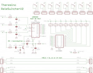
Questo modulo pilota otto relè (o altri dispositivi a bassa tensione). Per aumentare il numero di canali, si aggiungono altri moduli uguali. Si collega ogni modulo alla uscita del modulo precedente. Tutti i canali sono indipendenti e il numero di canali è praticamente illimitato. Il circuito stampato è progettato con tutti i componenti a passo 2.54 e senza sovrapposizioni di piste, per cui si può montarlo velocemente su una basetta millefori a una sola faccia (meno costosa).
Si parte da tre soli Pin, configurati come DigOut e si collega questo modulo alla fine di un lungo cavo schermato, con quattro fili interni (ma si potrebbe anche usare un cavo non schermato per citofoni). Il cavo può essere lungo molte centinaia di metri. Un solo modulo Master potrebbe pilotare due di queste linee, raddoppiando la velocità di esecuzione.
Attenzione: usare un 74AHCT595. Gli HC e gli HCT non funzionerebbero perché non hanno gli ingressi di tipo SchmittTrigger. I filtri dei segnali rallentano i fronti di salita e discesa e le versioni senza Schmitt Trigger potrebbero contare più impulsi, di quelli effettivamente inviati.
Miglioramenti rispetto alla versione precedente
- Il circuito è più semplice grazie allo ULN2803 che sostituisce i transistor di pilotaggio dei relè.
- Tutti gli ingressi sono filtrati in modo da evitare qualunque disturbo in arrivo dal cavo.
- Lo stato dei relè viene memorizzato fino a che è pronto lo stato seguente e il cambio avviene istantaneamente. (la versione precedente spegneva tutti i relè durante il cambio)
- E’ presente un circuito WatchDog che alla accensione tiene tutti i relè spenti, fino a che il computer non inizia a trasmettere.
- Il WatchDog controlla anche che il computer continui a inviare periodicamente il segnale “Store”. Quindi, se il computer si ferma o il cavo si stacca, dopo qualche secondo tutti i relè si spengono.
Con il watch si deve alzare e abbassare periodicamente il segnale “STORE”, almeno una volta al secondo. Qualcuno potrebbe quindi non volerlo, o magari fare le prime prove senza e aggiungerlo in seguito. Per eliminare il WatchDog si mette a massa il Pin 13 di IC1. E in questo caso si potrebbero anche eliminare i componenti R4, C4 D1, T1, C5 e R5.
Tensione di alimentazione dei relè
La alimentazione dei relè può essere lo stesso 5 Volt, in arrivo dall’USB e dal cavo di collegamento, ma si deve fare attenzione che:
– I relè devono avere la bobina da 5 Volt e possibilmente a bassa corrente.
– Il cavo di collegamento non deve provocare una caduta di tensione maggiore di un volt.
– La corrente di tutti i relè accesi non deve superare i 500 mA della porta USB.
Con il 5 Volt si dovrebbero poter pilotare circa 16 rele, con un cavo per citofoni lungo qualche decina di metri (per la alimentazione i cavi da citofono hanno due fili più grandi). Meglio comunque fare i conti, con la corrente dei relè e la resistenza del cavo.
Per aumentare il numero di relè e allungare il cavo senza limiti, si devono alimentare i moduli Rele Switcher, con un alimentatore locale da 5, 12 o 24 Volt.
Se si usa un alimentatore locale fare attenzione a non collegare per sbaglio il 12 o il 24 volt ai fili che vanno al Theremino Master.
Pilotaggio e tempi di comunicazione
La velocità di esecuzione dipende dal numero di canali e dalla velocità del PC. Con PC lenti si devono aumentare le pause tra i canali (nel software di comando). Normalmente un tempo di due o quattro millisecondi per canale è sufficiente, sui PC più lenti potrebbero servirne sei. Con quattro millisecondi per canale, i tempi sono i seguenti:
Numero di canali Tempo per trasmettere tutti i canali
8 32 milli secondi (31 Hz)
16 64 milli secondi (16 Hz)
24 96 milli secondi (10 Hz)
32 128 milli secondi (8 Hz)
64 256 milli secondi (4 Hz)
240 1 secondo
Con 8 canali il pilotaggio è così rapido che i relè non gli stanno dietro. Ma anche tempi oltre i 100 mS sono adeguati per queste applicazioni. I rele non sono progettati per commutare decine di volte al secondo.
Download del progetto in formato Eagle, simulazione LTSpice e immagini 3D:
https://www.theremino.com/files/Actuator_ReleSwitcher_V2.zip
Per un esempio di software di pilotaggio, aprire gli Script “ReleDriver”, che si trovano nella cartella “ReleDriver”, tra gli esempi di Theremino Script: downloads/foundations#script
L’esempio più aggiornato (che controlla anche il WatchDog del ReleSwitcher V2) è il “ReleDriverV6”.
Interruttore di sicurezza per applicazioni pericolose

Il Relè Switcher Versione 2 dispone di un circuito di sicurezza interno, ma in alcuni casi è meglio prevedere un secondo circuito di sicurezza, completamente elettromeccanico.
Tipici esempi sono le esplosioni scenografiche e i tubi esplosivi per il lancio di coriandoli.
In questi casi nel contenitore del Master, si aggiunge un deviatore, come quello mostrato qui a sinistra.
Questo deviatore intercetta il filo “STORE” e lo scollega dal segnale di uscita del Master (si deve usare un Relè Switcher Versione 2)
Se il deviatore è in OFF, allora il filo STORE, in arrivo dal cavo schermato, viene scollegato dal master e collegato al filo GND, dello stesso cavo schermato.
Se il deviatore è in ON, allora il filo STORE, in arrivo dal cavo schermato, viene collegato al filo SIGNAL che arriva dal Master.
Per ottenere la massima sicurezza si tiene questo interruttore sempre in OFF e lo si accende solo alcuni secondi prima dell’istante di start.
Prima di accendere ci si assicura che:
- Tutti i cavi siano collegati (exploders, cavo schermato, USB)
- Il software sia avviato e risponda ai comandi
- Tutti si siano allontanati dalla zona pericolosa
I nostri sono solo consigli tecnici, non hanno validità legale e non ci assumiamo nessuna responsabilità. Le applicazioni pirotecniche devono essere realizzate solo da personale dotato di licenza e iscritto al registro delle imprese che realizzano spettacoli pirotecnici (secondo gli articoli 47 del T.U.L.P.S. – art 101 Reg. T.U.L.P.S. e la Circolare del Ministero dell’interno 11/01/2001 559/c.2055.XV.A.MASS. )
Sostituire i relè con transistor
In alcuni casi potrebbe essere una buona idea, usare dei transistor al posto dei relè. Senza i relè la massa dell’alimentatore di potenza, deve essere in comune, con la massa della logica digitale, e infine, attraverso il cavo di collegamento, anche con la massa del Master da cui partono i segnali. Senza relè, si possono più facilmente ricevere disturbi, dall’alimentatore di potenza e dalla rete elettrica. Infine, senza relè si deve fare più attenzione, se si sbaglia qualche collegamento si potrebbero inviare i 12 Volt alla logica e bruciare gli integrati, o addirittura danneggiare il modulo Master.
Al posto del TIP 120 si potrebbero usare transistor simili (devono essere darlington e NPN). Oppure si potrebbero usare dei Mosfet di tipo N (facendo attenzione che lavorino bene, con tensione di gate inferiore a 3 volt). Mosfet adatti potrebbero essere gli IRLB8721 (30V 60A 2.5Volt-Gate 0.009ohm 0.5Euro circa). Oppure si potrebbero usare i BP318S o gli altri mosfet indicati in questa pagina per il DriverOnOff.
Su YouTube si può vedere come Orlano Pennino ha realizzato il Rele Switcher.
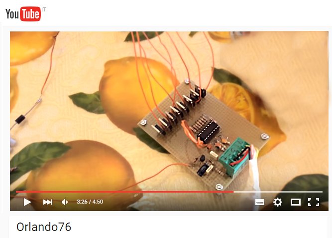
Orlando è stato l’ideatore di questo progetto, ha fatto i test di funzionamento e ci ha guidato nella realizzazione del software di controllo.
Regolatori di luce isolati
Questi regolatori sono simili ai normali “Dimmer” ma sono più lineari, sopportano anche carichi induttivi, sono protetti contro i corto circuiti e sono isolati fino a 3000 volt per la massima sicurezza.
Per lampade alogene e lampade a incandescenza ma anche trasformatori e motori fino alla potenza di 1000 watt…

Relè a stato solido
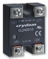
Questi attuatori esistono in due versioni, “zero crossing” e “random”.
I modelli “zero crossing” garantiscono che la commutazione avvenga sempre nel momento in cui la tensione è minima, riducendo a zero i disturbi elettrici causati dalla accensione e dallo spegnimento e possono quindi essere usati con qualunque tipo di carico dai più delicati a quelli difficili, induttivi e di grande potenza come saldatrici, puntatrici e grandi motori.
I modelli “random” commutano in un tempo molto breve (circa 1 mS) e possono essere quindi usati con una uscita Pwm per regolare la potenza in modo continuo ma attenzione: è possibile regolare in modo random solo i carichi resistivi, praticamente solo lampade a incandescenza e resistenze riscaldanti, gli altri carichi creerebbero fortissimi disturbi elettrici e potrebbero anche danneggiarsi.
Fare attenzione a scegliere modelli con pilotaggio in DC e con 3 volt di tensione minima, altrimenti con 3.3 volt non si riuscirà ad accenderli.
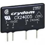
Connettere il filo di segnale (giallo) al punto 3 (+) ed il filo di massa (marrone o nero) al punto 4 (-)
I punti 1 e 2 devono essere connessi in serie al dispositivo da controllare facendo bene attenzione a mantenere un buona distanza di isolamento dalle connessioni 3 e 4.
Caratteristiche comuni per tutti i modelli
Insulation:     4000 volt
Voltage max:    280 Vac
Drive voltage:  3 to 32 volt DC
Drive current:  <10 mA at 3.3 volt
Working temp.:  -30°C to +80°C
Modelli reperibili presso Farnell
With "Zero crossing" driving
-----------------------------------------------------------------
SHARP-S202S02F  - Farnell 1618475 - 600 Volt / 8A - 4 euro
CROUZET-D2W203F - Farnell 1533334 - 280 Volt / 3A  - 13 euro
CROUZET-CX240D5 - Farnell 1533308 - 280 Volt / 5A  - 16 euro
CRYDOM-CL240D05 - Farnell 1833499 - 280 Volt / 5A  - 24 euro
CRYDOM-CL240D10 - Farnell 1833503 - 280 Volt / 10A  - 25 euro
CELDUC-SO842074 - Farnell 1305664 - 275 Volt / 25A  - 28 euro
With "Random" driving
------------------------------------------------------------------
CROUZET-CX240D5 - Farnell 2187747 - 280 Volt - 5A - 16 euro
CRYDOM-UPD2415F - Farnell 1779785 - 280 Volt - 15A - 30 euro
Motori e servocomandi
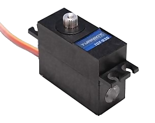
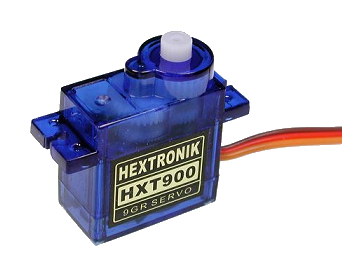
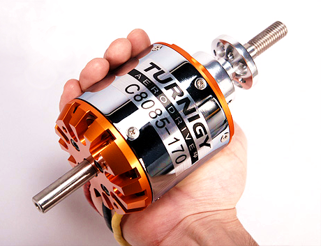
Esistono servocomandi e motori di ogni genere e potenza, sono ideali per molte applicazioni, si collegano ad un “Master” che ne puo’ pilotare fino a sei o ad uno “Slave” di tipo “Servo” che può pilotarne fino a dieci, si sceglie “Servo” come tipo di PIN e il gioco è fatto.
Per i particolari consultare la pagina: hardware/actuators/motors
Adattatori, regolatori di tensione, limitatori di corrente
Alcuni sensori e attuatori necessitano di alimentazione stabilizzata o limitata in corrente. In alcuni casi è anche necessario adattare il segnale da 5 Volt a 3.3 Volt.
Tutti gli adattatori sono raccolti qui:
www.theremino.com/hardware/adapters

