Filtri di segnale per la Spettrometria Gamma
Il filtro che si vede in questa simulazione fa parte delle prime ricerche, gli schemi definitivi del PmtAdapter sono qui: www.theremino.com/technical/schematics
I tre impulsi (negativi) visibili nella simulazione sono:
ROSSO: impulso prodotto dal tubo fotomoltiplicatore ( 1uS – 10 Volt )
BIANCO: impulso dopo la prima cella passa basso ( circa 10 uS – 1 Volt )
VERDE: impulso dopo la seconda cella passa basso ( circa 300 uS – 20 mV )
Solo il terzo impulso ( a volte chiamato “gaussiano” per la sua forma ) può essere campionato con precisione da una scheda audio. Il secondo impulso, per quanto rallentato, ha comunque la punta aguzza e solo raramente capiterà un campione esattamente sulla sua punta. L’impreciso campionamento produce un allargamento delle righe. Questo effetto viene minimizzato dagli impulsi con forma “gaussiana”, che forniscono una zona orizzontale abbastanza ampia, che minimizza gli errori anche a 48 KHz.
Quando si guardano gli impulsi con visualizzatori software queste forme sono molto smussate, a causa della limitata banda passante della scheda audio, e sembrano anche abbastanza larghi (decine di microsecondi) ma non ci si illuda: senza un doppio filtro RC gli impulsi in ingresso alla scheda audio sono stretti e aguzzi. Poi si allargano ma, anche se le loro caratteristiche non si vedono più, i danni li hanno già fatti.
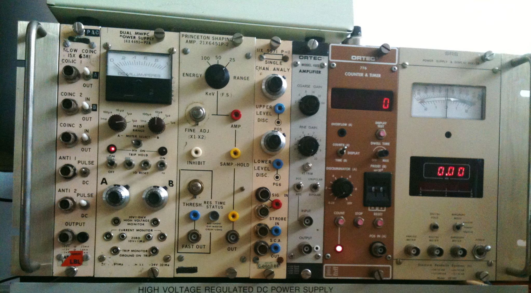
Confronto con i filtri e gli ADC hardware del secolo scorso.
Quanto sono belli questi moduli hardware dei Flintstones!
Peccato che dopo un po’ di anni i potenziometri cominciano a grattare, i commutatori a fare contatto solo di giovedì e che, anche nelle migliori condizioni, i risultati siano inferiori a quelli ottenibili in software.
Questi ADC hardware sono velocissimi (ma serve a poco) ma in compenso hanno un rapporto segnale rumore di soli 60 dB contro i 110 dB raggiungibili con gli ADC della schede audio recenti (e questi servono davvero)
Inoltre i loro alimentatori sono rumorosissimi (da 5 mV a 50 mV pep) in confronto agli alimentatori che usiamo attualmente (sotto i 200 uV pep)
Non si tratta solo di spendere tanto o poco, ci sono di mezzo 30 anni di miglioramenti.
Commenti
Naturalmente anche qui potete lasciare commenti, domande e consigli.


The user 81lmc7101, author of the http://www.youtube.com/watch?v=P_WpkaLX0BQ wrote: “Nice and powerful software! Thank you! Btw, low energy resolution is weaker than with PRA. Please, tell me about ideal pulse shape for this software – I will make filter.”
Without filter
——————————————————
Also without filtering it is also possible to get resolutions down to about 7% FWHM using the “BaseLine Restorer” and the “Dead Time”
– use a sampling frequency of 192 KHz (imperative without filters)
– set to 50 and 50 the “BaseLine Restorer” and 250 the “Dead time”
– do not send to the audio card input pulses with amplitude not more than some volt. (measured with a true hardware oscilloscope) (Note 1)
– set all the “Record Mixer” sliders to not more than 70%
– if your pulses are too much near one to other, please raise the distance from the radioactive sample to the scintillator (to get no more than 200..500 pulses per second)
Note 1
The audio card attenuates a lot the out-of-band pulses (pulses < 50uS) To get a useful signal with so short pulses the only method is to increase the pulse voltage. Someone sends to the sound card pulses of 1uS with a height of 30 Volt !!!!! In this situation happens the following: - the sound card input components are completely saturated - the linearity of the high energies is loosed (the poor PMT is not the responsable of this) - the antialias filter produces tons of ringing - the distorsions produced creates so much noise that the low details are completely masked With filter ------------------------------------------------------ The best filter is composed by two low pass cells With only one cell the top is too much sharp to sample it with precision. (please analyze the dots on the pulse top in the Pulse visualizer) It is also important to increase the rising time enought to eliminate ringings And, if possible, to completely eliminate the baseline shifting using "bipolar pulses", (pulses with the same positive and negative areas" Please write on our Blog so, with the help of the community, we will find the best circuit and schematics. In this page, with the halp of the community, we will find the best and simplest filter. Bye Livio
I would like to see digital filter at input to theremino mca having a high freq cutoff adjustable to 2khz or higher. This is to filter noise at the high frequency end. Would likely help a bit with pulse shape but really meant to minimize the noise floor.