
")
Il Theremino_MCA pur essendo completamente Freeware e OpenSource è un vero Multi-Channel-Analyzer da laboratorio.
Ulteriori informazioni:
– Schemi elettrici e piani di montaggio: www.theremino.com/technical/schematics
– Software: www.theremino.com/downloads/radioactivity
– Hardware, autocostruzione e kits: www.theremino.com/contacts/producers
– Immagini e Video: www.theremino.com/video-and-images
– Articolo su Elettronica Open Source: tecniche-di-condizionamento-del-segnale-spettrometria-gamma
——————-
Hardware per la Spettrometria Gamma


Il Theremino_PmtAdapter contiene un circuito di retroazione in grado di mantiene la tensione stabile anche in presenza di forti variazioni della temperatura. In questo modo la taratura rimane precisa nel tempo e le righe degli isotopi non si spostano e non si allargano.
ATTENZIONE: Per ottenere le prestazioni ottimali è necessario usare tubi PMT cablati come indicato nel file PmtAdapters.pdf – I tubi PMT a bassa impedenza (con resistori da 1 mega o addirittura da 560k) non possono funzionare con questi adapters. Per utilizzarli occorrerebbe sostituire i loro resistori come da noi indicato.
Questo adattatore può essere usato con il ben noto software freeware PRA (ringraziamo Marek Dolleiser per aver aperto la strada a questo genere di analisi, il suo software PRA è un riferimento da molti anni e ci ha aiutato molto) ma solo con il Theremino_MCA si possono fare operazioni di filtraggio e di cancellazione del fondo utilissime per ottenere il massimo di informazioni in tempi ragionevoli.
Questo file comprende il progetto del PCB, le immagini e le simulazioni SPICE: PMT_Adapter_V3.1
Questa è la versione 3.2 con molti piccoli miglioramenti: PMT_Adapter_V3.2
Questa è la versione 3.3 con ulteriori miglioramenti: PMT_Adapter_V3.3
Most salient features:
– Compact only 50 X 70 mm
– No initial thermal drift due to the feedback loop.
– Adjustable voltage from 500 to 1500 V
– Very low power consumption only 10 mA @ 5 V
– Very low ripple only 100 uV
– Protected against short circuit
– Maximum power output 100 mW
– Preamp circuit and pulse enlargement (from 3/5 uS to 100 uS to be read by a PC sound card)
Caratteristiche tecniche:
– Compatto solo 50 X 70 mm
– Nessuna deriva termica iniziale grazie al circuito di retroazione.
– Regolabile in tensione da 500 a 1500 V
– Consumi molto bassi @5 v solo 10 mA
– Ripple bassissimo solo 100 uV
– Protetto contro il corto circuito
– Potenza max erogata 100 mW
– Circuito di preamplificazione e allargamento degli impulsi incorporato (porta gli impulsi da 3-5 uS a 100 uS per essere letti da una scheda audio del PC)
La costruzione semplice e ordinata riduce i difetti di costruzione e li rende immediatamente evidenti.


Nelle seguenti immagini si vede il PMT durante le prove.


Lo schema elettrico e un impulso di esempio che mostra il livello di rumore dell’alimentatore, notare che si tratta di un impulso di bassa energia.


Nelle ultime versioni di PmtAdapter il rumore è inferiore ai 100uV. Praticamente il solo rumore dovuto al campionamento a 16 bit della scheda audio, come visibile nelle due immagini seguenti.


La prima immagine mostra il rumore della sola scheda audio, la seconda il rumore con il PmtAdapter collegato.
——————-
Il sistema completo


———————
Il Pmt Adapter non è in produzione, è possibile costruirlo ma contiene un certo numero di componenti speciali, difficili da reperire e costosi. Per cui si consiglia di rivolgersi ad Lello, che sa come reperire i componenti a buon prezzo e ha anche fatto stampare un certo numero di PCB per gli amici: ufficiotecnico@spray3d.it
Il team del sistema Theremino si occupa solo di ricerca e non vende hardware. Il sistema é completamente “Freeware”, “Open Source”, “No Profit” e “DIY”, ma esistono produttori che possono fornire i moduli assemblati e collaudati a un ottimo prezzo. Difficilmente si potrebbe auto-costruirli spendendo meno. Per un elenco dei produttori leggere questa pagina: www.theremino.com/contacts/producers
Uno zoccolo per il PMT Hamamatsu R6095 (e simili)


In questo file ZIP il progetto completo Eagle e il file GCode per la fresa: PMT_Socket


Queste immagini illustrano come adattare i connettori allo stampato e come viene lo zoccolo finito (fare click sulle immagini per ingrandirle)
Il condensatore potrebbe anche essere saldato dal lato opposto (con due tubetti isolanti sui reofori) e, per evitare cortocircuiti con il tubo di alluminio esterno, è bene avvolgere tutta la zona dal tubo PMT al circuito stampato, con un foglio di plastica isolante.
Un sistema MCA per Apple (iPhone e iPad)
A grande richiesta Alessio ha studiato una versione speciale di PmtAdapter, usabile con il software disponibile su iPhone e iPad. Il software si chiama Geiger bot, ed è un riferimento per la comunità Apple.

Lo schema elettrico è molto simile al PmtAdapter per PC, ma è stata aggiunta una batteria (non c’è la alimentazione USB). Inoltre il segnale viene ridotto notevolmente di ampiezza, per poterlo inviare all’ingresso microfonico, che altrimenti saturerebbe e distorcerebbe la forma degli impulsi.


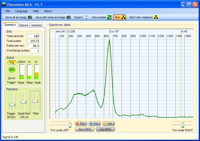
Qui si vedono gli spettri ottenuti con Americio e Cesio. Grazie alla meravigliosa risoluzione dei display “retina”, le scritte sono così piccole, che non disturbano la visione del bellissimo sfondo nero.
Siamo lontani anni luce da un vero MCA, la larghezza delle righe “FWHM” (che è il parametro più importante per un MCA) è esagerata. I particolari minori dello spettro sono completamente invisibili. Ecco gli stessi spettri prodotti da Theremino MCA:


Con un Tablet 12 pollici da 180 euro (con Windows 10 e spedizione compresi nel prezzo), si avrebbe uno strumento portatile molto più comodo e preciso. Ma la soddisfazione di usare un sistema Apple, che costa una esagerazione, non ha prezzo!
Calibrazione e temperatura
Il Pmt Adapter e il fotomoltiplicatore consumano solo poche decine di milli Watt, che non sono sufficienti a provocare variazioni di temperatura significative. Quindi non è necessario attendere un “tempo di riscaldamento” tra la accensione e le misure. E non c’è nemmeno un riscaldamento progressivo durante misurazioni molto lunghe.
Però i cristalli scintillatori cambiano rendimento con la temperatura ambiente, come si vede nella seguente immagine:

Si noti che la risposta alla temperatura non è lineare e che cambia addirittura pendenza da positiva a negativa, proprio nella zona delle normali temperature ambiente. Per cui una correzione automatica sarebbe imprecisa. Ci vorrebbe una tabella di correzione da calibrare per ogni cristallo e questo sarebbe molto complesso e in definitiva poco affidabile. Molto meglio effettuare una taratura con due marker prima di ogni misura.
Effettuare un controllo con i marker prima di ogni misura è un sistema rapido, preciso e molto affidabile. Si consiglia di mantenere sempre in posizione due piccoli campioni (ad esempio Cesio e Americio) a distanze opportune, in modo da avere sempre due piccole righe di riferimento. Il Cesio è più debole e lo si tiene abbastanza vicino alla sonda mentre l’Americio lo si tiene a una decina di centimetri, oppure lo si racchiude in una capsula, per diminuire la sua attività e poterlo tenere vicino alla sonda.
Le due righe dovrebbero essere della stessa altezza e abbastanza piccole da non disturbare le misure. Se non si devono misurare proprio il Cesio e l’Americio, allora i due marker possono stare sempre in posizione. Vedere le loro righe sul grafico finale (eventualmente commentate) da la sicurezza che il grafico è perfettamente calibrato.
Costruire un pozzetto in piombo
Da usare per misurare il Livello di Radioattività del fondo naturale e di sostanze debolmente radioattive.
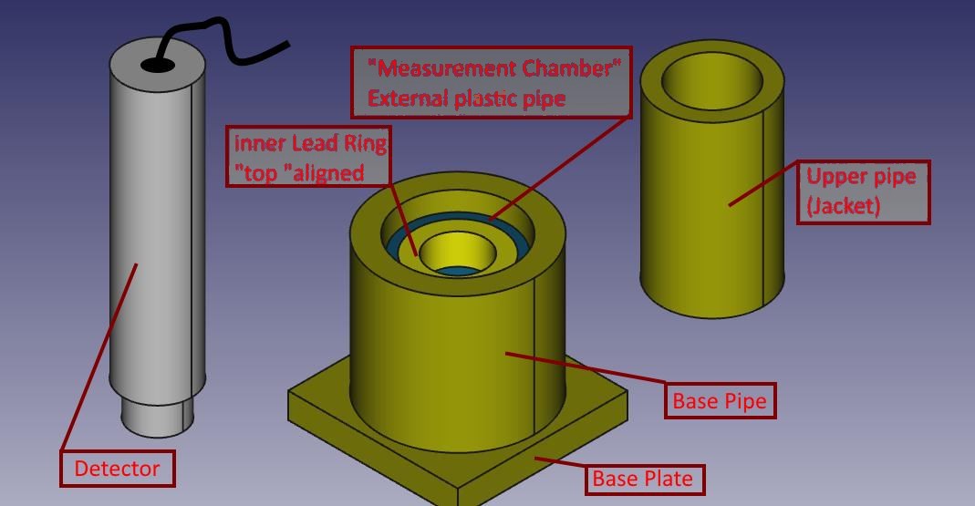
Il pozzetto di misura è costituito da una piastra di base, più alcuni cilindri concentrici, di varie misure e spessori. Tra i componenti si lascia un po’ di lasco, per facilitare l’assemblaggio.
Il materiale color ottone in realtà è il piombo, per distinguerlo dall’alluminio grigio della sonda, mentre il pezzo di cilindro interno (appena visibile) è l’unico di plastica, con anello concentrico e solidale in piombo.
Tutte le parti in piombo sono state realizzate a partire da lamiera da 1,5 mm di spessore, tagliata con una comune forbice da lamierino e sagomata a mano avvolgendola intorno a cilindri di alluminio/acciaio/plastica che avevo a disposizione (utilizzati solo come “dime”).
La piastrina di base è stata realizzata piegando più volte una striscia di lamiera di pari larghezza, ottenendo alla fine un discreto spessore.
La lamiera si piega facilmente attorno al bordo dritto di un tavolo e si appiattisce con colpetti di martello. Il piombo infatti è molto malleabile.
Tutti i pezzi sono stati avvolti con del nastro di carta sufficientemente largo, in modo che maneggiandoli non si viene in contatto diretto con il piombo, che tende sempre a sporcare le mani. Anche per questo è bene calcolare un po’ di lasco tra i vari diametri dei pezzi, in modo poi che il rivestimento di carta non crei problemi all’inserimento/sfilamento dei cilindri stessi, che parzialmente devono entrare uno dentro l’altro (come per il cilindro di base e la camicia superiore)
Per misurare si segue questo schema:
- Si pone innanzitutto su di un tavolo la piastra di base ed il cilindro di base;
- Si inserisce il campioncino da sottoporre a test dentro il tubo di base, in modo che sfiori la parte interna (più bassa) dell’anello della camera di misura: si possono infilare sotto ad esso degli opportuni distanziatori;
- Si mette la camera di misura (cilindro plastica ed anello piombo solidale) in modo che il sottostante campioncino sia centrato sul fondo dell’anello;
- Si infila la camicia superiore all’interno del cilindro di base: essa si appoggerà al tubo di plastica e si manterrà concentrica al foro dell’anello di piombo in modo da permettere il successivo inserimento della sonda;
- Si inserisce la sonda : nel mio caso a incastro nell’anello di piombo della cameretta di misura.
Dalle prove che ho fatto questo setup riduce il rumore di fondo da quasi 20 cps a 3,1 cps
Marco Russiani
Download di questo progetto, completo di ulteriori informazioni e immagini:
![]() Theremino_Pozzetto_di_Misura_ITA.pdf
Theremino_Pozzetto_di_Misura_ITA.pdf
![]() Theremino_G-Ray_Test_Chamber_ENG.pdf
Theremino_G-Ray_Test_Chamber_ENG.pdf
Currently using Dolleiser’s PRA (Pulse Recorder & Analyser version 15.0.1.0) would very much like to try the MCA unit as described. Where do I obtain the hardware and software? This is a small research project for Dully Research Inc.
Regards, Marty
Our software is Free and Open Source, you could use it with your hardware, download it from here:
https://www.theremino.com/en/downloads/radioactivity#mca
Our hardware is explained here:
https://www.theremino.com/en/technical/schematics#pmtadapter
If you can not make it DIY then you could write to Alessio that helps the Makers with components and preassembled parts: alessio.giusti@meteolink.it
Addition info about radioactivity and spectrometry:
– Electrical schematics and Assembly plans: https://www.theremino.com/en/technical/schematics
– Software: https://www.theremino.com/en/downloads/radioactivity
– Hardware, DIY and kits: https://www.theremino.com/en/contacts/producers
– Images and videos: https://www.theremino.com/en/video-and-images
In the download page and in the application folders you will find many useful documentation.
thank you for your prompt response, very much appreciated will follow your steps as outlined.
Sig Cicala,
I really appreciate your paper “Tecniche di condizionamento del segnale per la Spettrometria Gamma”. Unfortunately I speak almost no Italian. So I used a few Linux programs and Google translate to convert your paper to English.
It may not be of any use to you, but if you would like my English translation of your paper — I would be honored to email you a copy.
My project will most certainly build off of your work and I have already credited you on my project blog.
This is a good idea, thanks!
You could send the file to engineering@theremino.com and we will publish it.
Excellent and decent post, I found this much informative, as to what I was exactly searching for. Thanks for such post and please keep it up.
Thank you for your great work. We are using the Theremino MCA 7.1 software in our university research and we are very happy with it (in combination with a Gamma Spectacular driver and an X-ray probe).
One problem we have is that the background spectrum (zero input, no sources) looks different when I connect to the computer that runs Theremino MCA 7.1 remotely via Teamviewer. In that case, we start to get much more counts/noise/pileup in the low KeV region. When I disconnect from Teamviewer and start a new run, then the counts in that region are down again.
I suspect this has to do with the CPU load of the computer that runs Theremino MCA. Teamviewer adds about 20% CPU load when connected. I suspect similar issues may occur when the CPU load varies due to other reasons e.g. due to Windows Update, virus scan etc. This is a problem for us since we need to have a high reliability of baseline spectra, as long as no source is present. Have you encountered such an issue before i.e. that the spectra change depending on the CPU load even if the input signal remains the same (background with no source in our case)?
Tested now with TeamViewer and no difference in noise observed.
So I suggest to make further tests in the following areas:
– The Audio-Recording panel properties (Maybe you selected stereo-mix instead of microphone? Maybe you are not using the modifyed audio card? Maybe some recording property changes when TeamViewer uses the audio?)
– The TeamViewer audio preferences. Try to set properties to not use audio.
– The power supply that comes from the USB and goes to the audiocard (maybe the 5 volt noise increases when using TeamViewer).
Thank you very much for your quick response, Livio. I will carry out more tests here and will report back with more detailed information.
Hi Livio, I observed this issue over time and I think the last suggestion that you made was the solution: once I switched from the computer’s USB 5V supply to a lab power supply with 5V DC, the problem stopped to show up.
We use the Gamma detector close to an ultrasound transducer. When we’re very close, we sometimes get pulses which are clearly not due to radiation but due to certain kinds of ultrasound-induced mechanical vibrations affecting the detector. Fortunately, in the pulse shape visualizer, I can easily identify those “fake” pulses because they don’t have a real peak and stay up for a long time. See the screenshot here: https://ibb.co/dXJmFv. Unfortunately, Theremino MCA still recognizes them as valid pulses. Would it be difficult to change the Theremino MCA source code such that these type of fake pulses without real peaks are filtered out and treated as invalid? Thank you for any help or any advice!
The pulse detection code has been stable for many years and works so well that we prefer not to risk generating defects. And anyway it would be just a patch.
Since you see impulses, it should not be difficult to find a solution to eliminate them.
Inside the probe there is a very delicate photomultiplier tube containing metal grids and thin links. Certainly the ultrasound generates resonances in some of these connections. It is also possible that some of these details of the PMT tube will break because of vibrations.
I therefore suggest finding ways to mechanically isolate the probe.
Thank you very much, Livio, for your advice. I tried my best to mechanically isolate the probe with all kinds of foam and damping materials. This helped a lot and reduced the occurrence of the fake peaks maybe by 95%. However, we still get some fake pulses and therefore unreliable results, so I decided to finally consider filtering the remaining ones out on the software side.
I completely understand that changing the main branch of the Theremino MCA code is risky, given how well it works. Instead, I was thinking about making a few small adjustments to the source code on my computer (i.e. reject pulses that stay up) and recompiling locally.
I have a lot of programming experience but not so much with VB, so it would help a lot if you could briefly point me at the file in the VB project where I have access to the data for every pulse that is visualized in the pulse shape visualizer and where it is determined whether a pulse is valid or not. Just pointing at the right file/place in the project code for me to look at, would be super helpful. Thanks a lot!
1) Please install Visual Studio 2008 as explained here:
https://www.theremino.com/en/downloads/notes-on-software#development
2) Set the visual studio ambient as explained here:
https://www.theremino.com/en/downloads/notes-on-software#visualstudio
3) Open the “Class_WaveRecorder” and find the function “DataArrived” at line 146
All you need is in the “DataArrived” function, good luck.
Ciao premetto che sono profano in radioattivita e spettrometria, ma per vari motivi mi serviva sapere se potete consigliarmi un sensore simile a questo qua e con caratteristiche simili ihttp://www.atomtex.com/en/products/radionuclide-identification-devices-rids/at6101-at6101b-spectrometers
da usare col theremino, aggiungo che la particolarita è che deve essere molto sensibile e direttivo cioe mi serve individuare sorgenti gamma anche se di pochi mm e molto deboli…grazie
Con il sistema theremino potresti costruire qualcosa di molto simile e con le stesse prestazioni.
Ti serve un fotomoltiplicatore, un cristallo NaiTl, un PMT adapter, la applicazione Theremino MCA e un Tablet con Windows. Parti dalla applicazione Theremino MCA e troverai i link a tutto il resto:
https://www.theremino.com/downloads/radioactivity
A differenza del dispositivo che hai indicato non avrai un pannello LCD e dei pulsanti ma dovrai utilizzare un Tablet con touch Screen (o un computer fisso per misure in laboratorio).
Se vuoi aiuto per la costruzione chiedi ad Alessio, c’è il suo indirizzo di posta qui :
https://www.theremino.com/contacts/about-us#alessio
Consigli
– – – – – – – – – – – –
Il dispositivo che hai indicato promette mari e monti ma “dimentica” di spiegare che la realtà è molto meno piacevole di quello che sembra a leggere le sue caratteristiche. Innanzi tutto questi apparecchi sembrano misurare verso il davanti ma non sono per niente direzionali. Più vai vicino alla sorgente con la punta e più segnano, tutto li. Ma se li giri di fianco e vai vicino alla sorgente con la punta segnano uguale. Se la sorgente è piccola basta che ti allontani di un metro e non segnano quasi più niente. Se invece è grande (ad esempio tutto intorno a te) allora comunque ti giri e ti sposti misurano sempre uguale.
Un’altro aspetto che non appare a leggere quello che hanno scritto è che la sensibilità alle basse radioattività si paga con il tempo. Per misurare basse radioattività, appena superiori al fondo ambiente allora non si va in giro con la bella maniglietta che mostrano nella loro immagine ma si accende l’apparecchio e lo si lascia fermo per un’ora prima di avere misure ragionevolmente precise.
Diverso sarebbe se si lavorasse in una centrale nucleare e si andasse in giro con la tuta. In questo caso si potrebbero fare misure rapide, diciamo di trenta secondi l’una. Ma non credo che sia questo il caso.
Infine bisogna anche dire che gli isotopi che normalmente si possono trovare sono quattro o cinque. Gli altri difficilmente li si possono trovare fuori da una centrale o dai laboratori medici. E ci vuole anche molta esperienza per capire qualcosa di affidabile dagli spettri. Quindi se lo si fa per imparare va benissimo, ma se si pensa di utilizzarlo realmente le cose cambiano. C’è da studiare per mesi o anni e alla fine misurare più o meno quello che già c’era da aspettarsi. Un po’ di cesio nel’ambiente, qualche campione di prova e nient’altro di utile.
Ciao Livio e grazie per la risposta, riguardo l’estetica del progetto non mi interessa molto ma piu che altro la sostanza… vado dritto al problema cosi capisci di che si tratta: io vorrei individuare i nodi Hartmann.
Nel suo libro”Salute dell’Habitat” il professore di fisica nucleare Nicola Limardo (ha insegnato all’Harvard Univ. e La Sapienza di Roma), spiega come ha individuato i nodi hartmann,(cosa fattibile finora solo da sensitivi con delle bacchette) con una termografia a infrarossi o con uno spettometro nucleare con sonda in germanio (ha usato anche quello del CERN Di Ginevra e dell’ENEA) o con un Geopotenziometro (che non conosco…).
in quei punti ha trovato appunto una radiazione di gamma ionizzante, molto debole dello spessore di un micron di radio226. Questa radiazione potratta per ore puo creare geopatologie e malattie molto gravi, e l’unico posto in cui stiamo tante ore è la stanza da letto, percio sarebbe buono controllare questa zona con questo strumento. Inoltre se ricordo bene invece il potassio-40 influenza molto la tiroide e ha potuto constatarlo anche con una termografia al centesimo di grado che questa radiazione produceva una ipotermia, anche se molto debole.
Lo spettometro segnalato da me con un link è uno di quello usato da lui,se ho capito bene, quello che chiedo è se vale la pena tuffarmi in questa impresa che mi affascina molto.
Cioe io riuscirei a costruire con una cifra non troppa esosa (anche alcune centinaia di euro) uno strumento similare? (quello di Limardo costa oltre 30.000E) oppure la rilevazione potrebbe essere un ardua impresa visto che la rete con questi nodi sono distanziati di circa 2m e posizionati in uno spazio di pochi mm o addirittura micron!?
Grazie
Puoi costruirlo con meno di 300 Euro. Chiedi ad Alessio per maggiore precisione.
Secondo la mia esperienza non misurerai niente di significativo, solo rumore e eventi casuali. Ma la storia è piena di cose ritenute impossibili che poi erano vere, quindi se proprio ci tieni è giusto che tu ci provi.
scusami,ma non riesco a trovare la sua email….su questo sito e meteolink non c’è
La trovi in : Contatti / Colaboratori / Alessio
E’ un po’ mascherata : “Mail: makers at theremino dot com”
Ma vuol dire : makers@theremino.com
Hi
Thank you so much for your valuable site.
I’d like to know the maximum number of pulses per second that we can count using your device.
I would be very grateful, if you could give me your feedback.
Regards,
Amir.
What device, the GeigerAdapter or the PmtAdapter ?
In the first case (GeigerAdapter) it depends from the Geiger tube used.
Tubes heve normally dead times from 50 to 250 uS
Tubes with a dead time of 50 uS can count to about 10’000 pulses per second.
Tubes with a dead time of 250 uS can count to about 2’000 pulses per second.
If you plan to use the Geiger Adapter with so high radiation levels then it is better to configure the Master input as FastCounter (not simple Counter).
In the second case (PmtAdapter) it depends from the gaussian shaping circuit that produces pulses of about 100 uS.
So the max counting rate will be about 5’000 pulses per second.
Thank you for your detailed reply.
But this count rate is so low for most applications. We need to count more than 50’000 pulses per second for our application at our lab. I would be very happy, if you could give me your suggestions about the suitable circuit for this purpose.
Regards,
Amir.
It is not a “circuit” problem, no geiger tube could count 50000 pulses per second.
And if, supposedly, you have a tube that emits more than 5000 pulses per second, instead of making measurements, you should run away as quickly as possible.
So there must be some misunderstanding. First of all, are you talking about a geiger tube? So what type of geiger tube you intend to use? And what source should emit these incredibly strong radiations?
hello,
I would appreciate any help with my problem.
I attempt install Theremino_OSC_UDP_Linux_V1.0 but run into a problem i can not solve.
Essential it is a missing system dll – but I do not know which one.
the debug level “critical” gives the output below.
Best wishes
Erich
Unhandled Exception:
System.TypeInitializationException: The type initializer for ‘Theremino_OSC.Theremino’ threw an exception. —> System.DllNotFoundException: ThereminoSlots
at (wrapper managed-to-native) Theremino_OSC.ThereminoSlots+MemoryMappedFile_Unix:the_slot_init ()
at Theremino_OSC.ThereminoSlots+MemoryMappedFile_Unix..ctor () in :0
at Theremino_OSC.ThereminoSlots..ctor () in :0
at Theremino_OSC.Theremino..cctor () in :0
— End of inner exception stack trace —
at System.Threading.ThreadHelper.ThreadStart_Context (System.Object state) in :0
at System.Threading.ExecutionContext.RunInternal (System.Threading.ExecutionContext executionContext, System.Threading.ContextCallback callback, System.Object state, Boolean preserveSyncCtx) in :0
at System.Threading.ExecutionContext.Run (System.Threading.ExecutionContext executionContext, System.Threading.ContextCallback callback, System.Object state, Boolean preserveSyncCtx) in :0
at System.Threading.ExecutionContext.Run (System.Threading.ExecutionContext executionContext, System.Threading.ContextCallback callback, System.Object state) in :0
at System.Threading.ThreadHelper.ThreadStart () in :0
[ERROR] FATAL UNHANDLED EXCEPTION: System.TypeInitializationException: The type initializer for ‘Theremino_OSC.Theremino’ threw an exception. —> System.DllNotFoundException: ThereminoSlots
at (wrapper managed-to-native) Theremino_OSC.ThereminoSlots+MemoryMappedFile_Unix:the_slot_init ()
at Theremino_OSC.ThereminoSlots+MemoryMappedFile_Unix..ctor () in :0
at Theremino_OSC.ThereminoSlots..ctor () in :0
at Theremino_OSC.Theremino..cctor () in :0
— End of inner exception stack trace —
at System.Threading.ThreadHelper.ThreadStart_Context (System.Object state) in :0
at System.Threading.ExecutionContext.RunInternal (System.Threading.ExecutionContext executionContext, System.Threading.ContextCallback callback, System.Object state, Boolean preserveSyncCtx) in :0
at System.Threading.ExecutionContext.Run (System.Threading.ExecutionContext executionContext, System.Threading.ContextCallback callback, System.Object state, Boolean preserveSyncCtx) in :0
at System.Threading.ExecutionContext.Run (System.Threading.ExecutionContext executionContext, System.Threading.ContextCallback callback, System.Object state) in :0
at System.Threading.ThreadHelper.ThreadStart () in :0
WARNING: The runtime version supported by this application is unavailable.
Using default runtime: v4.0.30319
We abbandoned all the Linux (and Mac) developments because there are too much problems.
Maybe you could try with Wine.
You could also write to our Linux expert Roberto at: development@theremino.com
Sorry
Livio
Hello,
I am wondering if you have a recommendation for a NaI Scintillator manufacturer?
Mainly you find on Ebay Probes from Gammaspectacular. I guess they would match. Gammaspectaular is also providing a MCA (e.g. GS-1100-PRO). Does the MCA fit somehow to Theremino MCA?
Secondly I find some units from Scionix 38B57. Do they need to be changes like you described in “Strange wired PMT tubes”? Or only when they have separate Power and Signal output.
The other option I found are those “Turnkey MCA sytems from the US. They have their own software (seems proprietary) using a PicoScope with 10MHz Bandwidth. I am also wondering if that may work together with Teremino (I guess no). But the idea with a chep DigiScope instead of a soundcard sounds interesting. Do you think the higher bandwidth may be a benefit? But those scopes cannot stream continuously, so I am wondering how it is done exactly…
Finally, I am wondering how to forward detected pulses from Theremino MCA > Theremino Geiger. It is mentioned that this works somehow only using software, but how?
Thank you,
Martin
If you use our PmtAdapter then the photomultiplier MUST be have an high impedance resistor chain. Otherwise any PMT tube can work, but you get more noise in the low energy area.
The Theremino_MCA application works only with an audio card input.
The Theremino_MCA application is written for the audio card signal (with a gaussian conditioning circuit that limits the band to 20 to 100 KHz max) it will not work with a 10 MHz band.
I would recommend using exactly the PMT tube and the PMT adapter we designed. In my opinion, any change over our project will only worsen the performance. Read this document:
https://www.theremino.com/wp-content/uploads/2012/11/MinimizingFWHM_ITA_ENG_PDF.zip
Hello again,
to my question before: I noticed that it is possible to use GS-1100-PRO with termemino => answered.
How do you estimate the GS-1100-PRO in comparison to Theremino MCA?
Thanks,
Martin
It will work and could be a good idea if you need a complete (non DIY) system.
We have not tested it.
Maybe you will get a little more noise in the low energy area but it will work very well.
I am using Teremino MCA with a geiger tube connected just for the purpose of counting and forwarding the impulses to Theremino Geiger.
Unfortunatelly, it counts much more than what is really there.
E.g. counts 60/s, I get 180.
I tried to change almost anything possible on the options.
Before I hat 50us peak length that worked, but now peak is 75us rectangular and has a slight overshoot at the end and ripple in between, I think that this is counted as peaks as well.
Is it possible to simply use a threshold and noise level and thats it? Or how do you think I may resolve it.
Solved… I am using AudioInput that works. If you still have a solution based on MCA please let me know. I’ll try older versions till then…
The application MCA requires gaussian shaped pulses coming from a photomultiplier tube. So geiger pulses are not correctly recognized.
You must read the geiger pulses directly with the Theremino Geiger app.
There are three metods:
1) A “Geiger Adapter” and a “Master module”
2) The application “Theremino Bridge”
3) The application “Audio Input”
https://www.theremino.com/en/technical/schematics#geigeradapter
https://www.theremino.com/en/technical/schematics#masterv5
https://www.theremino.com/en/downloads/radioactivity#bridge
https://www.theremino.com/en/downloads/multimedia#audioinput
Hello Livio,
Greetings from Australia.
Glad I found this page.Thank for all your inspiring work and those of the team Theremino. After reading the the theremino history I can see how it all came about and showing that with
love of a subject great things are possible – inspiring.
This is what wrote today to nkom but it seems to be appropriate here too. I cannot attach the spectra here but can send them if you like by email:
A few days ago I finished the basic build of a low noise battery power supply for a PocketGeiger type 4 for the Iphone from Radiationwatch.org in Japan and managed to take two spectra before the unit stopped working. I might have blown it up somehow but since ordered a replacement.
The spectra are attached and should show Am241 and Thorium but show something completely different. Has this to do with the pulse lenght which is meant for the Iphone mic input or is there perhaps another reason? What can I do to fix this?
I also noticed on the spectra that they only display spectra down to about 15 KeV. Is there a way to display spectra down to say 2 KeV?
The X100-7 diode used in the PocketGeiger shows in its specification graph a high sensitivity starting in this range and that is the reason for me using it for my low energy XRF spectrometer project. I am aware of the noise issues and might even try to TE cool the detector housing.
As for the isotope identifier – is it possible to extend it for XRF so that it also can identify elements from their fluorescence?
Last but not least I like to thank you for making this fabulous tool freely available for builders and experimenters as all the team of the Theremino crew does. Much appreciated!
Kind regards
Eckhard Werner
It is Difficult to help you trim your instrument. I have never used Radiationwatch’s PocketGeiger and Iphone and so I do not know why they do not work well.
However I think the only way to have good spectra is to use a photomultiplier and a NaiTl crystal. And this is even more true if one thinks of the very low energies needed for XRFs.
Hi Livio,
The Theremino MCA manual states “Adjust the audio signal (note 1) so that the VuMeter
specifying at least 30% and not more than 95% and that the program tell Signal OK”. This what I have done when I didn’t have a lead castle. Now that I made a lead castle, the ambiant noise is reduced and therefore I have “No audio signal” warnings in the absence of a radioactive source. Is that a problem ? Should I raise the volume so that the Vu meter is between 30% and 95% when placed in the lead castle ? Best regards, Sébastien.
Normally the backgrond pulse frequency is enough to suppress this warning. But maybe with a high thickness lead castle you could get a warning.
In any case, this is only a warning and does not produces side effects. So if the cesium and americium rows are in the right position then all is ok.
Hi!
Can you add the partlist on site? I think it’s easier to find the parts with a partlist.
For every device there is a project and you can download it. In the projects there are PCB images, schematics, and all you need to make them. To open projects the freeware application called Eagle is required.
Frank ci ha scritto
Scrivo chiedere informazioni in merito all’utilizzo di uno scintilaltore (CsI:Tl) con Theremino MCA. In sostanza vorrei utilizzare lo scintillatore insieme con un circuito (input_to_MCA) che tira fuori, per ogni evento che fa “scattare” il diodo, delle curve a campana senza l’uso del PMT.
Quindi il sistema sarebbe scintillatore->Circuito Adattamento -> Theremino MCA
Risposta
Fino ad ora tutti quelli che hanno provato i diodi hanno ottenuto risultati pessimi
Il rumore è molto maggiore rispetto a scintillatori e fotomoltiplicatore, per cui sotto ai 200 kEv non si misura niente. Inoltre la sensibilità (numero di impulsi al secondo) è minore e quindi il tempo di analisi si allunga.
http://physicsopenlab.org/2018/09/23/photodiode-and-csitl-scintillator-with-micod-csa-sa/
Comunque per fare funzionare il diodo con la nostra applicazione MCA bisogna che:
– L’uscita vada verso un ADC a 16 bit della scheda audio
– Gli impulsi siano allargati ad almeno 100uS in modo da essere leggibili con banda passante della scheda audio
– La forma degli impulsi sia “gaussiana” (arrotondati sopra e non a punta)
– Le frequenze sotto ai 10 KHz vengano attenuate dal circuito in modo da ridurre il rumore
Tutti questi condizionamenti sono attuati nel nostro PMT adapter e sono spiegati nei file di documentazione sul nostro sito e nel download della applicazione MCA
Link utili:
https://www.theremino.com/downloads/radioactivity#mca
https://www.theremino.com/blog/gamma-spectrometry/signal-filters
https://www.theremino.com/blog/gamma-spectrometry/hardware-tests
https://it.emcelettronica.com/tecniche-di-condizionamento-del-segnale-spettrometria-gamma
https://www.theremino.com/wp-content/uploads/2012/11/MinimizingFWHM_ITA_ENG_PDF.zip
https://www.theremino.com/wp-content/uploads/files/SiPM_ITA.pdf
Frank ci ha scritto
Grazie per la risposta esaustiva.
Quindi, se ho ben capito, il mio scintillatore potrebbe essere usato con il vostro PMT ?
Non mi è molto chiara la larghezza di almeno 100 uS: in tal modo non aumento in modo consistente il “tempo morto” …ovvero posso perdere tanti impulsi di larghezza inferiore ?
Risposta
Non “con il nostro PMT” ma con la nostra applicazione MCA. Invece il PMT (photo multiplier tube) andrebbe usato con i cristalli scintillatori NaiTL, non con il fotodiodo.
Allungare a 100uS è assolutamente necessario per passare attraverso la scheda audio, unica strada percorribile per avere un ADC a 16 bit il quale è assolutamente necessario per avere le righe strette (basso FWHM)
Leggi questo documento a pagina 14 che parla dei BIT dell’ADC
https://www.theremino.com/wp-content/uploads/2012/11/MinimizingFWHM_ITA_ENG_PDF.zip
Allargando gli impulsi a 100uS non “si perdono quelli di larghezza inferiore”. Tutti gli impulsi sono stretti ma vengono tutti allargati dal circuito di condizionamento.
Quello che si perde sono alcuni impulsi che fossero troppo vicini tra loro. Quindi se la radioattività è troppa, gli impulsi al secondo sono troppi e non si riesce più a fare buoni grafici (non conta quanti impulsi si misurano, conta solo la forma dei picchi dello spettro).
Quindi con 100uS non potrai misurare alte radioattività, ma tanto in quei casi più che misurare si scappa.
Nei casi normali si ha una radioattività molto bassa e il problema di perdere impulsi non esiste. E comunque in queste analisi quello che conta è fare un buono spettro, non raccogliere tutti gli impulsi. Molti impulsi (quando sono di forma strana) li si scartano apposta per avere una analisi più precisa.
Se avessi un campione troppo radioattivo, che da troppi impulsi e rovina lo spettro, basta allontanarlo un po’. Ma nella realtà i campioni sono sempre troppo deboli, fanno pochi impulsi al secondo e ti costringono a tempi di analisi molto lunghi.
Ciao, forse la mia domanda non è molto pertinente a questo blog… ma secondo voi esiste qualche strumento per misurare i cosiddetti biofotoni emanati dal corpo? Esaminati e studiati dallo scienziato Popp?
Aggiungo che i biofotoni sono stati rilevati con fotomoltiplicatori, che sono usati anche in questo sito, solo che non conosco i dettagli di eventuali frequenze….
Ciao, i biofotoni sono stati osservati come luce che va dall’ultravioletto al visibile e fino all’inizio degli infrarossi (da 200 nm a 800 nm). L’intensità è molto debole, un massimo di 1000 fotoni al secondo per centimetro quadro. Come confronto un piccolo LED emette 50 miliardi di miliardi di fotoni al secondo
Traduco da Wikipedia
I biofotoni possono essere rilevati con i fotomoltiplicatori o mediante una camera CCD a bassissimo rumore per produrre un’immagine, utilizzando un tempo di esposizione di circa 15 minuti per i materiali vegetali. I tubi fotomoltiplicatori sono stati anche utilizzati per misurare le emissioni di biofotoni da uova di pesce e alcune applicazioni hanno misurato biofotoni da animali e umani.
E copio da altri articoli
La difficoltà di estrarre ed analizzare gli effetti presunti degli eventuali biofotoni tra le altre numerose interazioni chimiche tra le cellule rende difficile l’elaborazione di un’ipotesi verificabile. … Un articolo del 2010 rassegna discute varie teorie pubblicate in merito a questo tipo di segnalazione e individua circa 30 articoli scientifici sperimentali in inglese negli ultimi 30 anni che mostrano evidenze di interazioni cellulari elettromagnetiche.
Ed ecco i nostri consigli
Un fotomoltiplicatore utilizzato secondo i nostri schemi non misurerebbe niente perché noi lo colleghiamo per contare, e misurare l’energia, dei singoli fotoni. Questo ci è possibile perché i raggi X e Gamma hanno energie milioni di volte maggiori dei fotoni di luce visibile o ultravioletta. Quindi ogni fotone Gamma ci da un forte impulso elettrico, che comunque facciamo fatica a misurare e a distinguere dal rumore.
Per misurare i biofotoni il fotomoltiplicatore andrebbe collegato e alimentato in modo simile ai nostri schemi, ma il segnale di uscita sarebbe una variazione di tensione sul catodo che andrebbe misurata con circuiti analogici. E dato che il segnale sarebbe piccolissimo, sia la tensione di alimentazione del tubo, che il circuito di misura della tensione del catodo, dovrebbero essere particolarmente stabili. Inoltre le misure andrebbero fatte al buio totale, un buio che difficilmente è raggiungibile se non in camere apposite. Pensa che la luce che esce da un PC chiuso che dentro ha un piccolo e invisibile led sulla scheda madre, potrebbe essere migliaia di volte più forte dei livelli da misurare. E che quello che filtra da una serratura di una porta anche milioni di volte. E infine, importantissimo, i tubi fotomoltiplicatori vanno tenuti sempre nel buio totale, altrimenti si rovinano irreparabilmente. Se prendono un po’ di luce (ne basta pochissima), diventano così rumorosi da non misurare più niente. E poi ci vanno giorni al buio totale per recuperarli.
Inoltre i fotomoltiplicatori che utilizziamo noi sono come delle clave rispetto alle diavolerie fotoniche disponibili alla scienza più avanzata. Non ho neanche idea di cosa si potrebbe usare, probabilmente camere CCD raffreddate a elio liquido, oppure rivelatori al germanio iperpuro, o altri simili giocattoli che solo a premere il pulsante ON, hai già fatto andare migliaia di euro di spese, per non dire quel che costa costruirli.
In conclusione ti sconsiglio di acquistare un fotomoltiplicatore, collegarlo e provare. Perché anche nella migliore delle ipotesi il massimo che potresti ottenere sarebbe di convalidare l’esistenza di queste radiazioni, quindi niente di nuovo. Decine di laboratori hanno confermato che esistono, e hanno fatto misure molto più precise di quelle che potremmo fare noi.
Se sei intenzionato ad approfondire questo argomento la strada giusta sarebbe:
– Fare una lunga e noiosa ricerca in rete per arrivare alle relazioni dei laboratori
– Tradurre e studiare con cura tutte le relazioni
– Proporre una nuova ipotesi che altri non abbiano già proposto e sperimentato
– Studiare esperimenti che convaliderebbero la tua ipotesi
Tutto questo sarebbe da fare sulla carta e solo dopo si potrebbe pensare di toccare qualche componente elettronico. Se farai questo percorso poi ne saprai molto più di noi e quindi sarai tu a venire qui a scriverci quali componenti dovremmo usare e quali risultati dovremmo osservare per convalidare la tua ipotesi.
ok, ho capito allora non è proprio alla mia portata, Grazie Livio per la risposta.
Hi, will be there other versions of Theremino MCA ?
Hi Livio,
I got a very strange phenomena with Theremino MCA : in the high energy region (around 2600-3000 keV) I got two peaks that appear that are not real photo peaks. When I look the pulses for these energies, they look clipped. With the same audio settings and same gain those peaks do not appear when using Becqmoni. Could it be that Theremino MCA doesn’t handle well high energy pulses ? I can provide screenshot if needed just provide me with en email.
Please send the images to engineering@theremino.com
Hi. Do you have any design for low cost x-ray, alpha or gamma spectroscopy?
I have the sources emitting both radiations but I can not get spectra because I do not have an equipment.
Do you know any projects? Thank you.
Our spectrometry project is here:
https://www.theremino.com/downloads/radioactivity#mca
In the documentation you will find all the suggestions for the hardware construction.
We do not produce or sell equipments, but you can contact Lello for the hardware:
ufficiotecnico@spray3d.it
To buy other the theremino system components, you can read this page:
https://www.theremino.com/en/contacts/producers
What is the bin size that Theremino sets. Is this a constant size, and how does the bins- x1, x2, x5 change it? Can one set Theremino to save the signal recieved as a sound file as well as the histogram?
Last, are there any Thermino gamma spec users in London UK who might be willing to chat locally?
BINS
———————————————————————–
– Setting Bins “x 1” you get approximatively 3000 bins
– Setting “x 0.1” you get approximatively 300 bins
– Setting “x 10” or “x 50” you do not get 30 000 or 150 000 bins, because there is a limit at 4096 bins.
Why to set so large numbers (up t “x 50”) ?
Because this produces a good resolution in the low energy area (from 0 to 150 KeV)
AUDIO FILES
—————————————————————
Theremino MCA does not read or save audio files.
To record you could use some recorder application.
Than you can play the file as a normal audio file, with the usual Windows audio applications, and select the appropriate source in the theremino MCA.
LONDON USERS
—————————————————————
Sorry I do not know, but maybe someone could write a message in this blog.
Hi to find Theremino MCA users in London or UK you may want to subscribe to Facebook groups such as “Gamma Spectroscopy Forum” or “Radiation Nuts”. Many users here :)
Thank you for your great job.I have learn more about it.
I have downloaded the Theremino_MCA_V7.3_WithSources, and run it perfectly. I want to learn more about the pulse record, processing,and spectrum analysis. At last I can use the C# to programe the software using myself.
Regards, Marty.
Using SharpDevelop you could translate our app in C# in some seconds.
Please use SharpDevelop version 4.4 because in the following versions they have removed the translation options.
Thank you for your reply very much.
I will try to download and use SharpDevelop version 4.4 ,and translate the app in c#。
Do you have some paper about the theory of digital pulse processing in the software Theremino_MCA_V7.3_WithSources? I want to learn more about it. I can not find it in the this website. Can you help me?
Best regards, Marty
In this page you will find the links for all:
https://www.theremino.com/en/downloads/radioactivity#mca
Maybe for you the following links are the most interesting:
https://www.theremino.com/wp-content/uploads/files/ThereminoMCA_Deconvolution_ENG.pdf
https://www.theremino.com/wp-content/uploads/files/GammaSpec_ENG.pdf
https://www.theremino.com/wp-content/uploads/2012/11/MinimizingFWHM_ITA_ENG_PDF.zip
Other documentation (and the program help) is in the DOCS folder of the application.
The original docs are in this ZIP file:
https://www.theremino.com/wp-content/uploads/2012/11/MinimizingFWHM_ITA_ENG_PDF.zip
There is also an article written in italian (you could use Google Translator on the page with the right mouse button)
https://it.emcelettronica.com/tecniche-di-condizionamento-del-segnale-spettrometria-gamma
Salve,
ho visto il vs. software e sarei interessato ad utilizzarlo per un progetto di Citizen science.
Il problema e’ il costo rilevante delle sonde a scintillazione.
In rete ho pero’ trovato un vecchio progetto della rivista Elektor (novembre 2011 a firma di B. Kainka) che utilizzava fotodiodi e transistor modificati (BPW34, BPX61 senza vetro e un 2N3055 scoperchiato) e che, a loro dire, permetteva di misurare le emissioni alfa, gamma e beta.
Ora, conoscendo la serietà della suddetta rivista, non ho motivo di dubitare della validità del progetto.
La cosa che mi ha colpito di più, pero’, è stata sia l’economicità del progetto sia la piccola sonda che, ovviamente, esce con un segnale analogico.
Potrebbe essere una soluzione alternativa all’uso dei rilevatori a scintillazione?
Cordialmente
Il segnale in uscita dal circuito di Elektor non è analogico. Sono impulsi che vengono contati dal processore, infatti scrivono: “microcontroller-based counter, displaying the result in counts per minute”
Per cui con i fotodiodi potresti contare gli impulsi ma non fare spettrometria.
E per contare gli impulsi ci sono i tubi geiger, che costano poco e che vanno molto meglio di un fotodiodo (sensibilità notevolmente maggiore e minimo rumore di fondo).
Per cui, se vuoi costruire un apparecchio preciso e sensibile, ti consigliamo di comprare un tubo SBM20 su ebay e poi utilizzare una delle versioni dei nostri GeigerAdapter, un modulo Master per collegarti via USB (o un Esp32 per collegarti via WiFi) e la nostra applicazione Theremino Geiger.
La nostra applicazione (come tutto quello che c’è su questo sito) è totalmente gratuita, e per i componenti spenderai meno di cinquanta Euro, o anche meno di venticinque, costruendo da solo il GeigerAdapter e il Master su un Millefori.
Ecco i link che ti possono essere utili:
https://www.theremino.com/downloads/radioactivity#geiger
https://www.theremino.com/technical/schematics#geigeradapter
https://www.theremino.com/technical/schematics#geigeradapterdiy
https://www.theremino.com/technical/schematics#flintstones
https://www.ebay.it/sch/maxtheremino/m.html?_nkw=&_armrs=1&_ipg=&_from=
https://www.store-ino.com/
https://www.ebay.it/sch/i.html?_from=R40&_nkw=sbm20&_sacat=0&_sop=15