
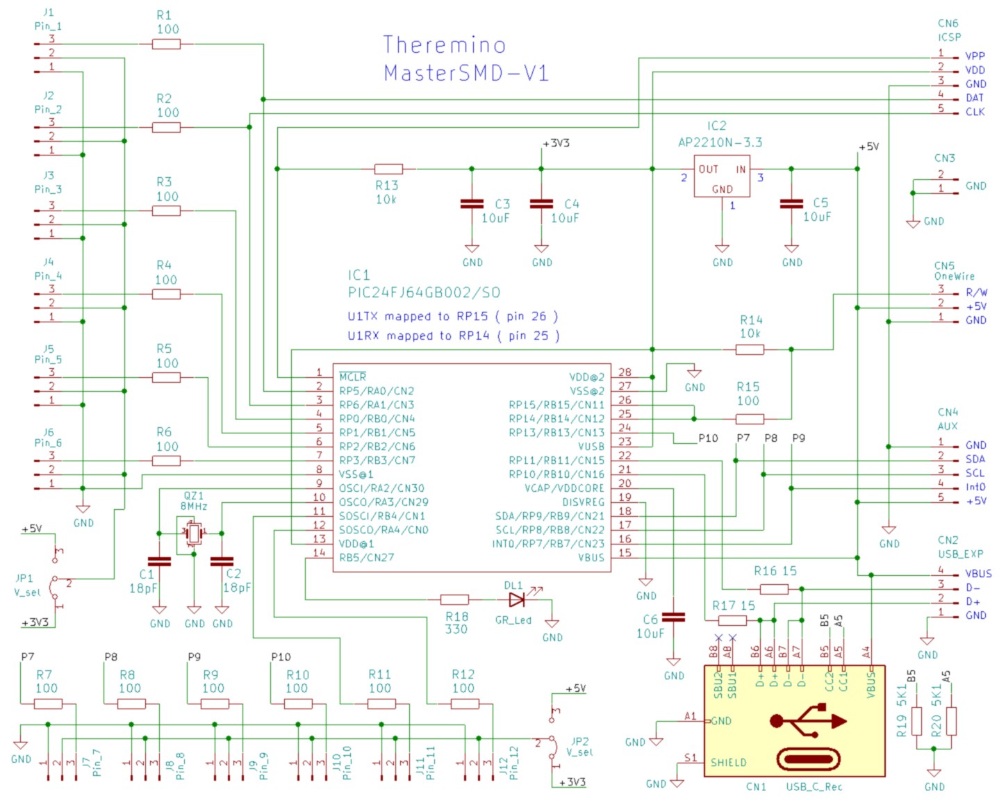
MasterSMD-V1
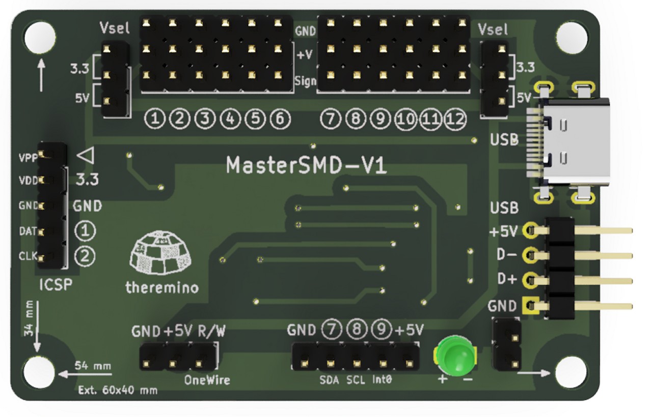
The SMD version of the card is essentially identical to the previous DIL V5 version, with the same applications and features. However, there are some differences that make the SMD version more convenient to use:
- The 12 In Out Pin connectors are all aligned, making it easier to connect cables.
- Each connector also has a GND connection and a power output, unlike the previous version where only six connectors had these features.
- Each group of six connectors can be set to power 3.3V or 5V sensors, offering greater flexibility.
- The USB connector is USB-C, as required for all new projects.
- Thanks to USB-C connector, the overall thickness of the board has been reduced.
- There is also a connector to 4 male pins on the right that allows you to connect multiple Master cards to a HUB without having to use bulky cables.
- Finally, there are two convenient connectors at the bottom to connect the Slaves and the ADC24.
- The two jumpers JP1 and JP2 are used to choose the voltage (3.3V or 5V) for the two groups of Pins.
- CN6 – ICSP – And’ the connector for programming but you can also use it to connect devices to GND, 3,3V and also to Pins 1 and 2.
- Cn5 – OneWire Property – Used to connect Slave modules, such as CapSensors.
- CN4 – AUX – Used to connect I2C modules (currently only the Theremino Adc24).
- CN2 – USB_EXP – Serves to connect multiple masters to a USB HUB module directly, without using connection cables. You will need a HUB with the female connectors arranged appropriately and currently we have not yet designed it.
- CN1 – USB_C – Can be connected with cables that go to USBC sockets, Usb3, USB2 or even USB1, and in all cases the performance does not change. The only advantage that can be obtained with USB3 and USBC is to be able to draw more current than the classics 500 mA of USB1 and USB2. The maximum withdrawable current should be 900 mA but may vary depending on device (PC, Mini PC, Notebook or Tablet that provides power).
MasterDIL-V5
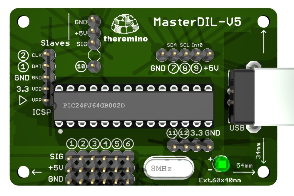
Version V5 is identical to the previous V4, but it has all the connectors on a grid with step 2.54 mm.
To use this new version doesn't have to learn anything new, you use exactly like previous versions, the Pin layout is almost identical and the Firmware is interchangeable.
Firmware V5 that you download from here is usable even on earlier versions of the Master (V4, V3, V2) and even on the first prototypes and DIY versions.
With firmware V5, as well as being able to connect the Adc24, you have a total of 12 In pin-Out, You can control up to twelve generic Pin, or up to five plus two generic Pin stepper motors.
STL files are also available to print a plastic support for the Master module 3D printers.
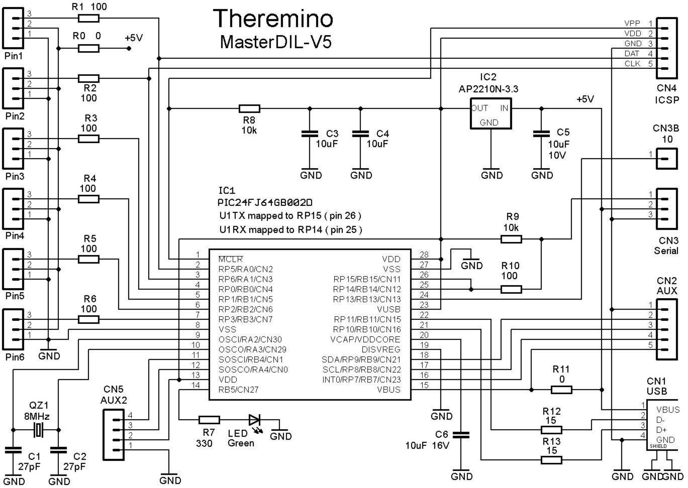
Design of MasterDIL-V5
This is the complete design of the PCB in Eagle format, with diagrams, Assembly plans and 3D images.
MasterDIL-V5 (file zip)
Firmware 5.0, It also enables communication with Adc24
Also includes the HEX file PicKit2 programmer, Pickit3 or similar.
MasterFirmware_V 5.0 (file zip)
Datasheets in PDF format
![]() MasterDIL-V5_Datasheet_ITA
MasterDIL-V5_Datasheet_ITA
![]() MasterDIL-V5_Datasheet_ENG
MasterDIL-V5_Datasheet_ENG
Datasheets in formato PDF DOC e XLSX
MasterDIL-V5_Documentation.zip
Masterdil-V4
 In this new version, locate the positions of the pins are easier, Why are represented by a circle. Also the new Pin (7, 8, 9, 10, 11 and 12) are referred to by their number. The PCB is simplified and reduced component count to increase reliability. The new version of firmware, also implements the reading of two phase Encoders and pins 11 and 12.

The small cylindrical quartz, which was present in earlier versions, was provided for the calendar, but it has never been enabled. So its lack does not determine any difference. We therefore decided to delete it and to use his connections to the pins 11 and 12, they are much more useful.
Anyone wishing to use the firmware Version 4 on older PCB version 3, should remove the cylindrical quartz and solder two males for the pins 11 and 12. If you do not use these pins, You can also let the Quartz, which does not generate no noise.
To use this new version of Master you should not learn anything new, you use exactly like the version 3, the Pin layout is almost identical and the Firmware is interchangeable.
Design of MasterDIL-V4
This is the complete design of the PCB in Eagle format, with diagrams, Assembly plans and 3D images.
Masterdil-V4 (file zip)
Firmware 4.0, empowering twelve Pin and Encoder types
Also includes the HEX file PicKit2 programmer, Pickit3 or similar.
MasterFirmware_V 4.0 (file zip)
Datasheets in PDF format
![]() Masterdil-V4 _ Datasheet_ITA
Masterdil-V4 _ Datasheet_ITA
![]() Masterdil-V4 _ Datasheet_ENG
Masterdil-V4 _ Datasheet_ENG
![]()
![]() Editable documents in ODT format – Italian and English
Editable documents in ODT format – Italian and English
Who knew these languages could open the file in Open Office, fix them and send them to us. For other languages, you can take the file and have it translated to English: www.onlinedoctranslator.com/translator.html that is great, a breeze and respects the formatting.
MasterV4_Docs_ITA_ENG
Masterdil-V3
(the original version of the master module)


For recommendations on the connections between sensors and the pins, read this page.
This third version of the master collects all the improvements and variants that have proved to be more functional. From version 3 in then screw connectors were replaced with male-female extension cables connectors. These connectors are less beautiful to look at but comfortable and reliable. (Screw connectors require a very small screwdriver, It was necessary to tighten them without too much force to avoid damaging the screw, But if the force was little they loosened over time. With new connectors, Instead, connections are fast and safe)
The circuit is very simple and very few components, QZ2 quartz can be omitted, serves only to stand-alone projects which require a few uA, for many years without recharging the battery (for example a Geiger-logger that must stay always on)
The PCB has six “PIN” (ten in the latest versions of firmware). The Master Pin can be used directly, no need to link modules “Slaves” to the serial line CN3. The connector CN2-AUX connect auxiliary devices, which counters, frequency meters and I2C devices (*). The connector CN4-ICSP allows easy programming “In circuit” with PicKit3 or similar type programmer.
All pins work between zero and 3.3 Volts, both input output. Special pins 7, 8 and 9 also accept signals from 5 Volts.
Processor programming PIC
For recommendations on programmers read this page: technical/pic-programming
With the new firmware from version 3.2 onwards, the number of pins increases from 6 to 10. Also available are new types STEPPERS and PWM_FAST. See "notes to the Master module and for the stepper motors.
Firmware 3.2, empowering ten Pin and sorts Stepper and PwmFast
Also includes the HEX file PicKit2 programmer, Pickit3 or similar.
3.2 MasterFirmware_V (zip file from 4 MByte)
Firmware 2.0, empowering six pins of InOut
Also includes the HEX file PicKit2 programmer, Pickit3 or similar.
MasterFirmware_V 2.0 (zip file from 500 Kbytes)
ATTENTION: Who was a Master of the first versions, quarts to 4 MHz, must change, in the File “common. h”, the following line:
from: #define CRYSTAL_4MHZ 0
 to: #define CRYSTAL_4MHZ 1
Then you have to recompile with MPLAB, and recreate the HEX file (Maybe calling it xxx_4MHz_xxx)
Design of MasterDIL-V3
This is the complete design of the PCB in Eagle format, with diagrams, Assembly plans and 3D images.
Masterdil-V3 (zip file from 1.5 MByte)
Master project DIY
This is the old version of master DIY (for the nostalgic) You should not use it but to use the new MasterDIL-V3 that contains many improvements. However the firmware does not change from version to version of PCB.
MasterDIL_DIY (zip file from 1.5 MByte)
Datasheets in PDF format
![]() Masterdil-V3 _ Datasheet_ITA
Masterdil-V3 _ Datasheet_ITA
![]() Masterdil-V3 _ Datasheet_ENG
Masterdil-V3 _ Datasheet_ENG
![]() Masterdil-V3 _ Datasheet_JAP
Masterdil-V3 _ Datasheet_JAP
More information
– Software: www.theremino.com/downloads/foundations
– Hardware modules: www.theremino.com/hardware/devices
– Images and videos: www.theremino.com/video-and-images
![]()
![]()
![]() Editable documents in ODT format – Italian, English and Japanese
Editable documents in ODT format – Italian, English and Japanese
Those who know these languages could open the file in Open Office, fix them and send them to us. For other languages, you can take the file and have it translated to English: www.onlinedoctranslator.com/translator.html that is great, a breeze and respects the formatting.
Master_Documentation_ITA_ENG_JAP
“Servant” (slave module)
increase in the number of pins to input output
SERVO modules are no longer used, instead of using the Masters that have many advantages.
- 12 Pin instead 10
- Safer communication (there is no serial which sometimes stops)
- Configurable pins with many types that are missing in Servos
We leave the following information for reference only
for those wishing to build them and possibly improve them.
– – – – – –
This module provides 10 Standard Input pin. Multiple slaves can be connected in cascade to further increase the number of InOut.
Servo modules do not have the corresponding Pin type Stepper and FastPwm.

For recommendations on the connections between sensors and the pins, read this page.
This module provides ten generic output input Pin. In addition to the sensors and actuators can be connected to the servo motors of all kinds.
Processor programming PIC
For recommendations on programmers read this page: technical/pic-programming
Project of the Slave Servo – V3
This is the complete design of the PCB in Eagle format, with diagrams, Assembly plans and 3D images.
Slave_Servo_V3 (file zip)
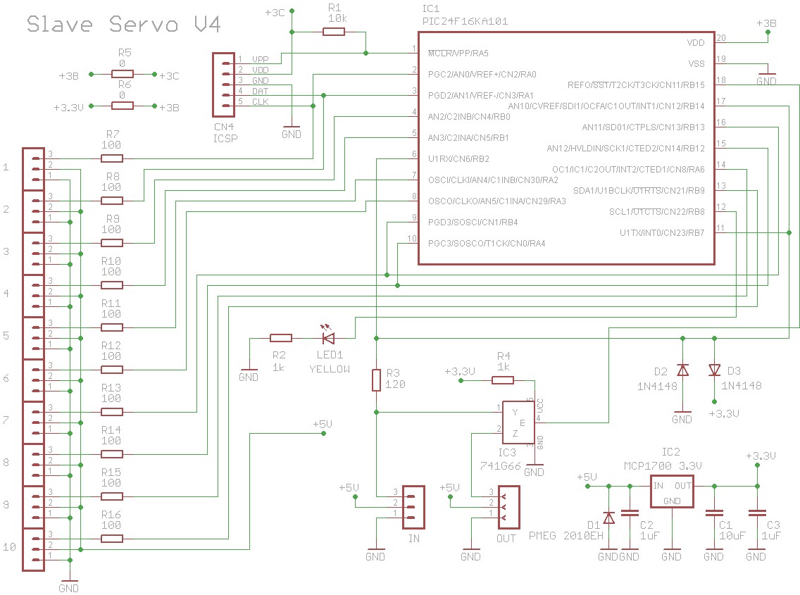
Project of the Slave Servo – V4
This is the complete design of the PCB in Eagle format, with diagrams, Assembly plans and 3D images.
Slave_Servo_V4 (file zip)
Slave Servo firmware
SlaveServo_Firmware_V1.1 (file zip)
The firmware version 1.1 fits all Servo modules. The versions of Servo modules from V1 to V4 are electrically all the same, change only the silkscreen. In V4 we corrected the ICSP pin arrangement because in previous versions the DAT and CLK pins were swapped.
Datasheets in PDF format
![]() Slave_Servo_Datasheet_ITA
Slave_Servo_Datasheet_ITA
![]() Slave_Servo_Datasheet_ENG
Slave_Servo_Datasheet_ENG
![]() Slave_Servo_Datasheet_JAP
Slave_Servo_Datasheet_JAP
More information
– Software: www.theremino.com/downloads/foundations
– Hardware modules: www.theremino.com/hardware/devices
– Images and videos: www.theremino.com/video-and-images
![]()
![]()
![]() Editable documents in ODT format – Italian, English and Japanese
Editable documents in ODT format – Italian, English and Japanese
Those who know these languages could open the file in Open Office, fix them and send them to us. For other languages, you can take the file and have it translated to English: www.onlinedoctranslator.com/translator.html that is great, a breeze and respects the formatting.
SlaveServo_Documentation_ITA_ENG_JAP
“Capsensor” (slave module)
detection of the position of a hand at a great distance

Firmware and Project of CapSensor
The construction, the calibration, testing and components of CapSensor are critical. Just, for example,, that is not right L1 brand (TDK), to considerably damage temperature stability and background noise. And TDK are found only by Mouser (20 Euro shipping). Effects are not to be neglected, switching from a range of several meters, a few centimeters. We want to avoid disappointment to car-builders and avoid us, having to adjust, via email, modules not working. Besides, If you count the time, to test and calibrate the firmware and all problems and disappointments, It costs much less buy them that make them. Therefore we advise you not to auto-build these modules.
To avoid disappointment it would be better not to publish the firmware, but since all our projects are Open Source… We also publish the new version of firmware with the new algorithm to “Dynamic latency”.
Slave project-CapSensor-V3
This is the complete design of the PCB in Eagle format, with diagrams, Assembly plans and 3D images.
Slave_CapSensor_V3 (zip file from 3.5 MByte)
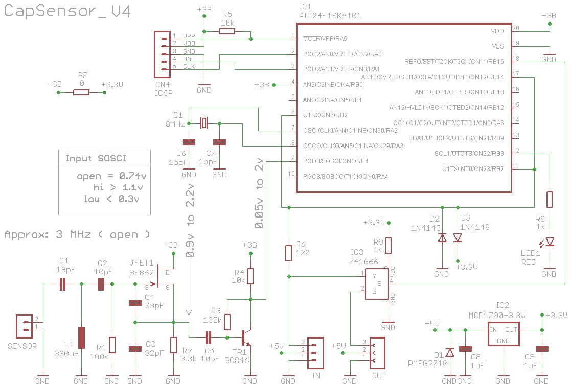
Project of the Slave-CapSensor-V4
This is the complete design of the PCB in Eagle format, with diagrams, Assembly plans and 3D images.
Slave_CapSensor_V4 (zip file from 3.5 MByte)
Capsensorhq – Firmware version 1 (for those wishing to try the previous firmware)
CapSensor_Firmware_V1
CapSensorHS – Firmware version 2.1 (with the new algorithm in dynamic latency)
CapSensor_Firmware_V2.1
The firmware version 2.1 fits all CapSensor modules. The module versions V1 to V4 are all electrically the same, change only the silkscreen. In V4 we corrected the ICSP pin arrangement because in previous versions the DAT and CLK pins were swapped.
Processor programming PIC
For recommendations on programmers read this page: technical/pic-programming
Advantages of CapSensorHS (Hi Speed) with firmware version 2 to “Dynamic latency”
- Incredibly low latency (up to 0.8 mS) When my hand is near and is moving fast.
- High accuracy by means of a long integration (up to 16 or 32 mS) When the hand is far away and moving floor.
- The tradeoff between latency and stability of notes (that is the big limit of all the Theremin), is improved by about 20 times.
- With the new firmware, the actual value of the latency is visible in the small window of parameters of HAL, under the graph of the oscilloscope (use the latest version of HAL).
- In version 2 We also improved event handling of interrupts and LowPriorityActivities. We thus removed small hops, that occurred to some particular frequencies of oscillator, and when the tainted value was exactly 458751 (6FFFF).
Test CapSensor
- Select the HAL line of CapSensor and set TipoPin = Cap_Sensor
- Double click on the CapSensor to open the oscilloscope
- Check in the value pane below, that your frequency is from 2.7 MHz to 2.9 MHz
- Press “View the raw values”
- Raise the “Vertical zoom” at most
- Press “Sets the zero”
- Check that the line is stable and not noisy. Normally the line drift slowly upward or downward and is only slightly rougher. Do this test without antenna and holding perfectly still on CapSensor and his strings.
Datasheets in PDF format
![]() Slave_CapSensor_Datasheet_ITA
Slave_CapSensor_Datasheet_ITA
![]() Slave_CapSensor_Datasheet_ENG
Slave_CapSensor_Datasheet_ENG
![]() Slave_CapSensor_Datasheet_JAP
Slave_CapSensor_Datasheet_JAP
More information
– Software: www.theremino.com/downloads/foundations
– Hardware modules: www.theremino.com/hardware/devices
– Images and videos: www.theremino.com/video-and-images
![]()
![]()
![]() Editable documents in ODT format – Italian, English and Japanese
Editable documents in ODT format – Italian, English and Japanese
Those who know these languages could open the file in Open Office, fix them and send them to us. For other languages, you can take the file and have it translated to English: www.onlinedoctranslator.com/translator.html that is great, a breeze and respects the formatting.
SlaveCapSensor_Documentation_ITA_ENG_JAP
“Master-ISO”
safe isolation of the serial line


The printout of this insulator allows you to mount the TMH0505S in two positions depending on whether you want to take the power from the Master (and then the USB) or if you want to feed the Master with the power coming from the Slaves (for Stand Alone applications)
ATTENTION: This is a deprecated project. When it was designed there were no commercial alternatives apply, but now there are USB and line insulators are fairly inexpensive. Isolate the USB line is better than isolating the only serial, you get a total separation between PC and IN-OUT modules. For which this module was never produced and was tested shortly. We do not recommend building it.
“PmtAudioAdapter – New version”
power supply unit 100 to 1800 Volts for PMT and Geiger tubes
This new version has improved features, is more compact, does not need the modified sound card or even the current limiter. In addition, the absence of the connection cable allows to obtain an even lower noise.

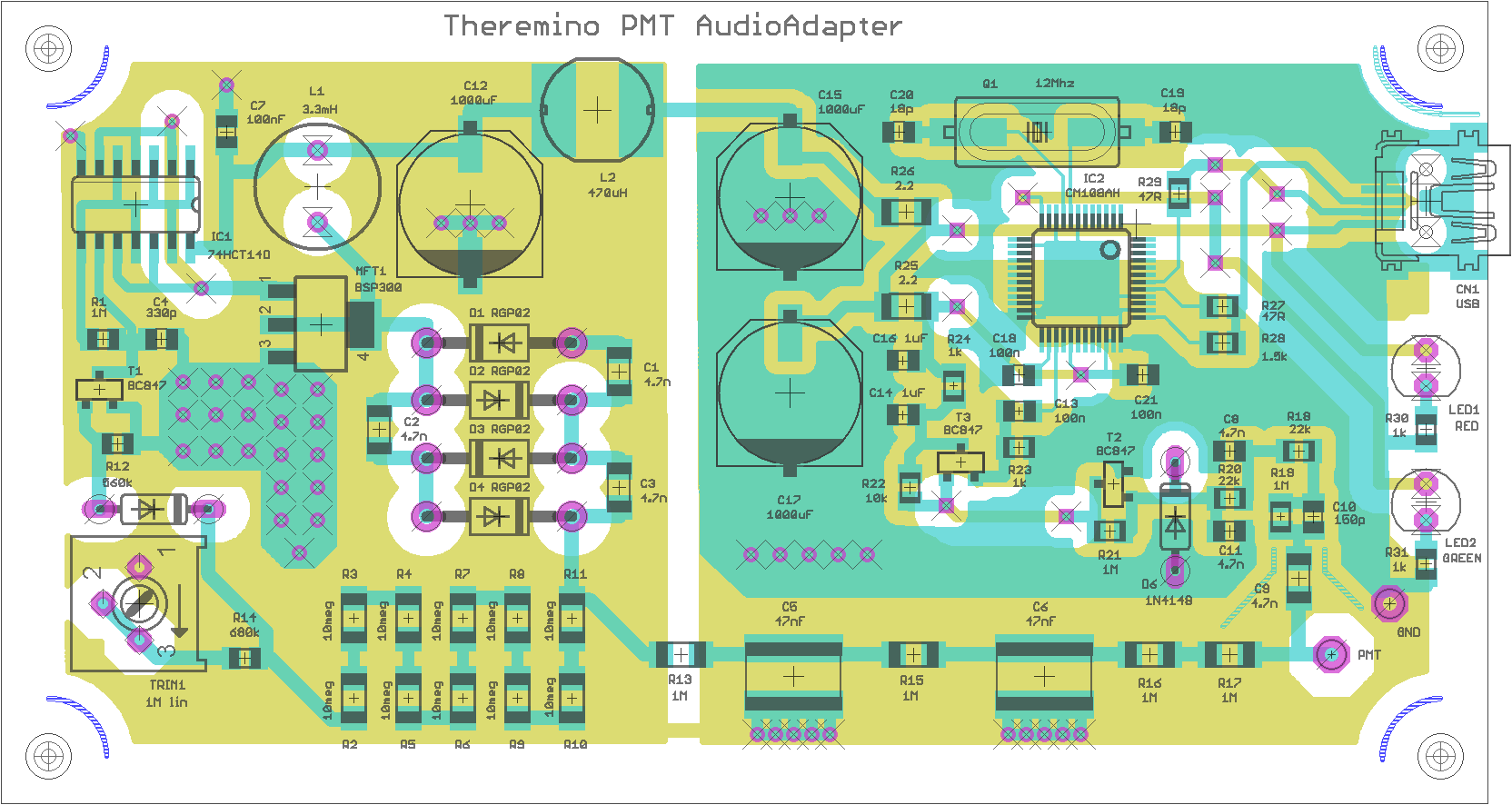
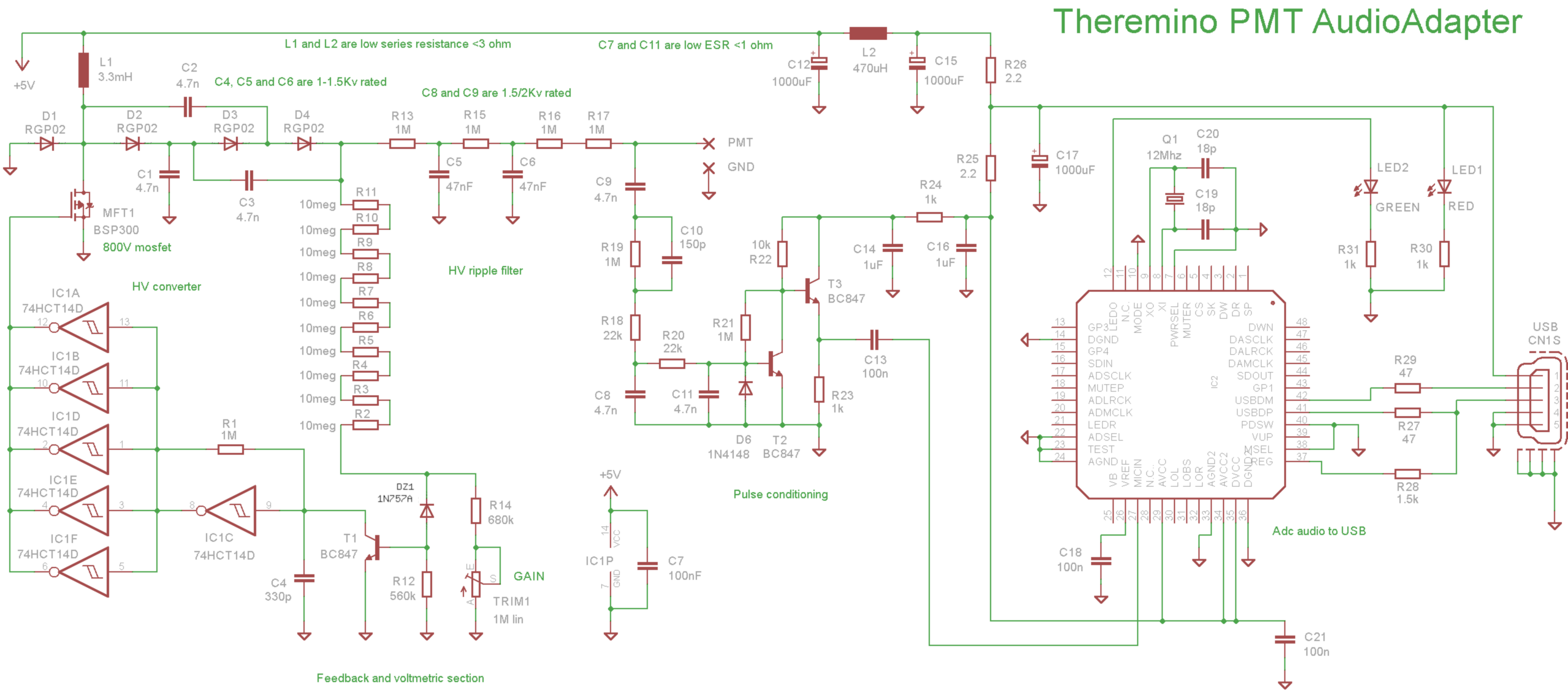
The basic features are the same as the first version that you find in the following chapter.
To have the PMT Audio Adapter in KIT or mounted contact Lello on this page
If you need the files to modify the PCB ask Lello to send them to you.
“A separate – Original version”
power supply unit 100 to 1800 Volts for PMT and Geiger tubes
This power supply, It has great features, consumes very little (from 10 but to 30 mA) and stabilizes the output voltage, in order to maintain a constant scale of energies. The output signal is conditioned in such a way “Gaussian” and “bipolar” for maximum measuring resolution.


The transistor T1 is an alternative to the mosfet MFT1, If you mount one mounts the other. With the mosfet efficiency is greater. For recommendations on the connections between sensors and the pins, read this page.
The normal range of this power supply is from 500 to 1000 volts. Replacing R101 you get a range from 700 to 1500 Volts. And’ can also go down to 100 Volts and up to 1800 Volts (raising R101 tension subsides and vice versa).
And’ You can also connect a Geiger tube instead of the PMT and send impulses to ThereminoGeiger via ThereminoMCA or via ThereminoAudioInput. This way you can feed even Geiger tubes from 900 Volts and beyond. For pipes 300, 400 or 500 Volts you can extend the range downward adjustment by increasing R101 or using a Qtr1 from 2.2 or from 4.7 Mega. Adjustable tension also allows you to experiment and measure the unknown Geiger plateau.
Datasheets in PDF format
![]() PmtAdapters_ITA
PmtAdapters_ITA
![]() PmtAdapters_ENG
PmtAdapters_ENG
![]() PmtAdapters_JAP
PmtAdapters_JAP
Download the complete project
This file contains the PCB project Eagle, 3D images and simulations LTspice: PMT_Adapter_V 3.3
More information:
– Software: www.theremino.com/downloads/radioactivity
– Gamma Spectrometry: www.theremino.com/blog/gamma-spectrometry
– Hardware, DIY and kits: www.theremino.com/contacts/producers
– Images and videos: www.theremino.com/video-and-images
![]()
![]()
![]() Editable documents in ODT format – Italian, English and Japanese
Editable documents in ODT format – Italian, English and Japanese
Those who know these languages could open the file in Open Office, fix them and send them to us. For other languages, you can take the file and have it translated to English: www.onlinedoctranslator.com/translator.html that is great, a breeze and respects the formatting.
PmtAdapters_Documentation_ITA_ENG_JAP
“The geigeradapter”
adapter between Geiger tubes and PIN standard
This power supply, It has great features, consumes only 10 UA, able to operate from only 3.5 Volts, its output is very stable and easily adapts to all municipalities Geiger tubes.


The normal range of this power supply is from 300 to 500 volts. The tensions 400 and 300 Volts are achieved by activating the points marked with 400B or 400A 300A with 300B.

The Geiger tube must always be connected at touring “Geiger +” and “Geiger GND”, do not connect the cables from the Geiger tube the plots called 300, 400 and 500, which are intended for the voltage selection.
In case of long links (more than what metro between GeigerAdapter and Master), You must use a shielded cable and follow these instructions: sensors * connections
The actual voltages are kept slightly low, in order to make work the tubes in the lower half of the plateau (This slightly decreases the sensitivity of Geiger but greatly reduces the number of pulses spurious products) You may experience this effect with a counter-evidence: If you run a Geiger near the maximum voltage sensitivity grows slightly but the number of pulses of background gets very high, until, arriving at the maximum voltage of plateau, the pipe starts to download constantly and produces thousands of spurious pulses per second.
For tubes from 300 Volts (they have a narrower platform) the reduction is a few volts while those from 400 and from 500 you work in practice about 380 Volts and 475 Volts (the 5% less than the rated voltage) This improves the stability of the rows when the impulses to be measured are few compared to those produced by tube, Basically when you measure the environmental fund.
For pipes that need 10 Meg, as the LND712, you add a resistor from 4.7 Mega in series with the positive wire going to the Geiger tube. This causes the 4.7 Mega exterior, is added to the 5.6 Mega on the printout and you will get around 10 Meg.
The SMD version is not easily changeable but the scheme also applies to versions Thru-Hole and also with quite different characteristics. For example substituting T1 with a MJE13003 (the transistors found in fluorescent lamps from a few Watts), C1, C2 with capacitors from 1500 Volts and C3, C4 and C5 with capacitors from 800 Volts you could run it up to 1400 Volts (for very high voltages and depending on the current required some modification to values for some components may be necessary)
In a non-SMD diodes D1, D2, D3 and D4 may be replaced with the RGP02-20. In any case you should use zener with very low leakage current otherwise the tension is not reached or falls when the room temperature grows. If you do not have very low leakage current zener you can replace two resistors R7 and R8 1 Mega. With resistors 1 Mega salt consumption by normal 10 UA up to 150 UA but the diode leakage current becomes tolerable.
Datasheets in PDF format
![]() GeigerAdapter_Datasheet_ITA
GeigerAdapter_Datasheet_ITA
![]() GeigerAdapter_Datasheet_ENG (09 Sep 2013 updated with little corrections)
GeigerAdapter_Datasheet_ENG (09 Sep 2013 updated with little corrections)
![]() GeigerAdapter_Datasheet_JAP
GeigerAdapter_Datasheet_JAP
Eagle project downloads that includes the simulation LtSpice, the 3D images, the GCode for you who want to make the PCB with the cutter and the Eagle PCB: GeigerAdapterV3.zip
A Council: Don't do this at home! The components are critical. The construction techniques must be adapted. Choose rather versions: DIY and Flintstones.
More information:
– Software: www.theremino.com/downloads/radioactivity
– Geiger: www.theremino.com/blog/geigers-and-ionchambers
– Hardware, DIY and kits: www.theremino.com/contacts/producers
– Images and videos: www.theremino.com/video-and-images
![]()
![]()
![]() Editable documents in ODT format – Italian, English and Japanese
Editable documents in ODT format – Italian, English and Japanese
Those who know these languages could open the file in Open Office, fix them and send them to us. For other languages, you can take the file and have it translated to English: www.onlinedoctranslator.com/translator.html that is great, a breeze and respects the formatting.
GeigerAdapter_Documentation_ITA_ENG_JAP (09 Sep 2013 – ENG version updated)
Geiger Adapter DIY
Some auto manufacturers have requested a GeigerAdapter, easily Constructible. So we designed this version just for them. All components are readily available but there are three or four SMD components at the bottom. Those who want a larger version, Constructible even on a thousand-holes, can use version “Flintstones” discussed in the next section.


The power consumption is low enough (from 100uA until some but depending on the output voltage set). With common components, and without the zener with very low leakage current (only available in the USA with 30 Euro shipping) You can't get incredibly low consumption of our SMD version (10 UA).
On the other hand, it is easy! And it is also easily adaptable to any tension from 100 Volts up to 600 Volts (and beyond) changing the value of the resistor R8. (and maybe even remodeling R9 and increasing C5 in some cases, Depending on the used zener)
The transistor MJ13003 (or 13002) can be derived from compact fluorescents no longer work. (look for those little, from 10 Watts or less, the lamps do not contain the 13002 or 13003 but other larger transistors) Even the inductance L1 can be derived from fluorescent lamps (usually the lamps contain an inductance from 1 MH up to 5 MH. They're all inductance values that go well, but with 5 MH lowers the power consumption)
Download the complete project that includes the simulation LtSpice, the 3D images, the GCode for you who want to make the PCB with the cutter and the Eagle PCB: GA500_DIL_V1
Geiger Adapter DIY – Flintstones Version


On request, Here is the version for the late Neolithic. The pace of the resistors is 10 mm, then you can use resistors 1/4 Watts. There are no components in the lower face and all components are placed in step 2.54 mm (so that can be built on a thousand-holes or on slabs of stone drilled)
The electrical characteristics are the same as the previous version DIY. The voltage for the geiger can be adjusted from 100 Volts up to 600 Volts and beyond. The wiring diagram shows the power consumption and other useful details.
Download the complete project that includes the simulation LtSpice, the 3D images, the GCode for the milling cutter and the Eagle PCB: GeigerPterodapter_Flinstones
Attention: There are unapproved copies of our forms. These products differ mechanically and electrically by our projects and have a Copyright, so I'm not really Open. According to our rules are unreliable and poorly designed products, see here. So we won't provide updates and support for them. The only products manufactured by following our instructions, can be found at: thereminoshop (Shenzhen China), Amazon (Yuntab-WaveGroup), eBay (Maxtheremino) and, handcrafted construction not for profit, Alessio (makers@theremino.com).