
Consigli per le macchine CNC
Chi avesse bisogno di consigli sui motori da usare, sui componenti meccanici o su come montarli e acquistarli, può rivolgersi a Fabio di Arezzo che negli ultimi anni ha raccolto molta esperienza sulle frese CNC e le macchine per incisioni con i laser.
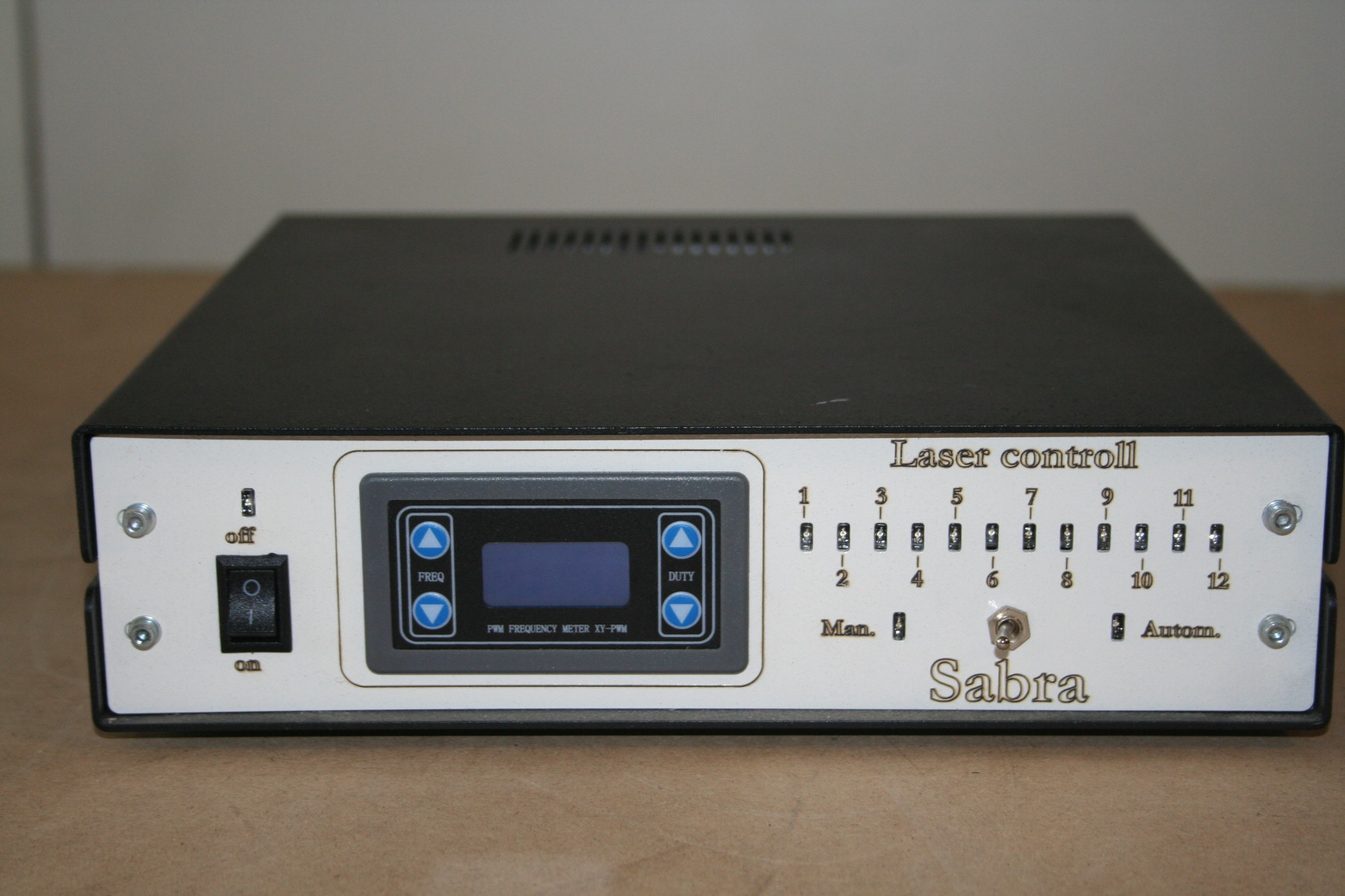
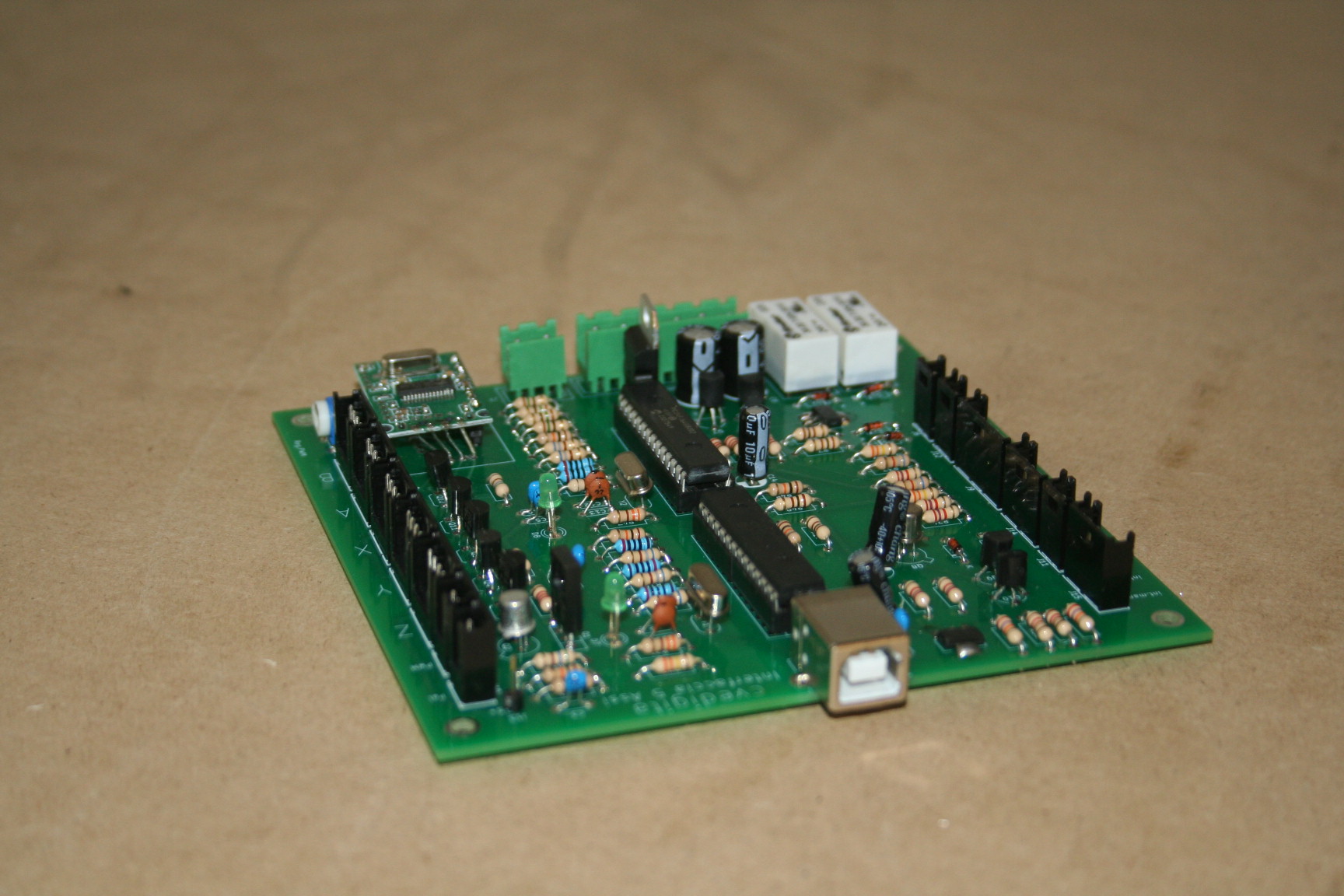
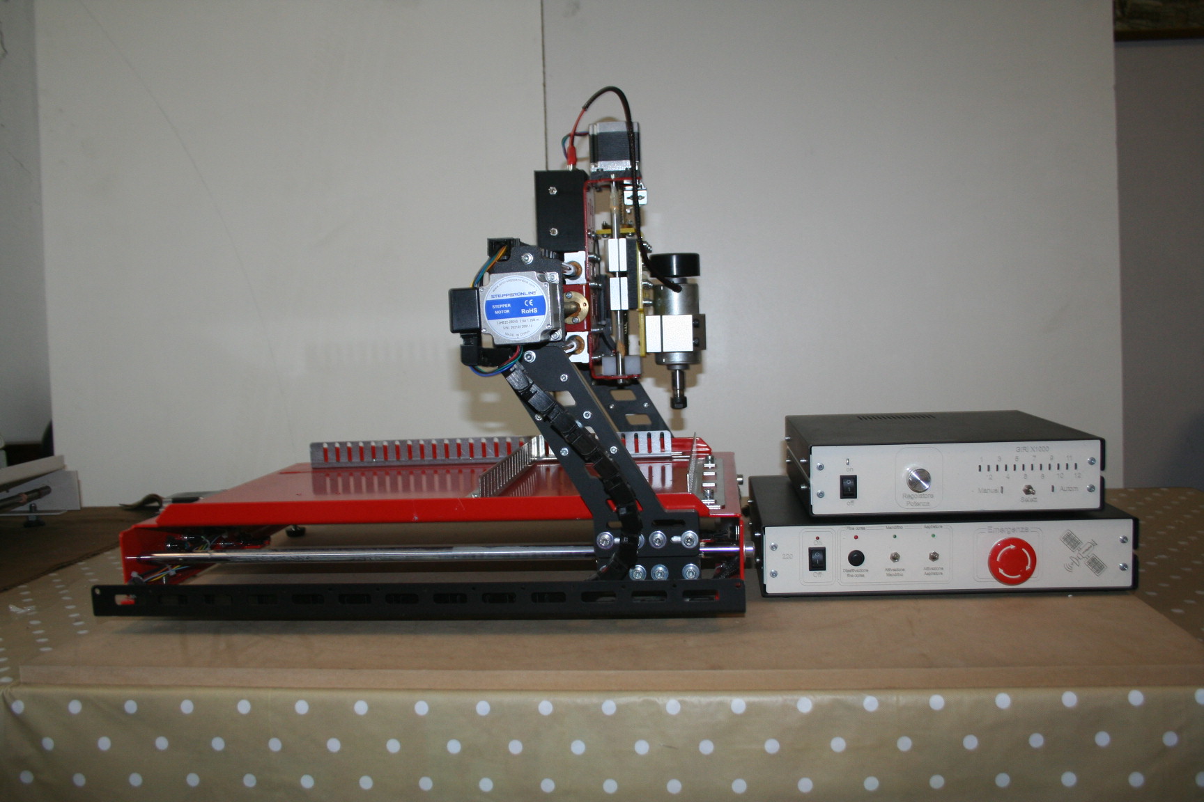
Nelle prossime immagini si vedono alcune sue realizzazioni. Cliccando le immagini si ingrandiscono e si può notare che sono macchine combinate, cioè che si può montare sia un laser che una fresa.
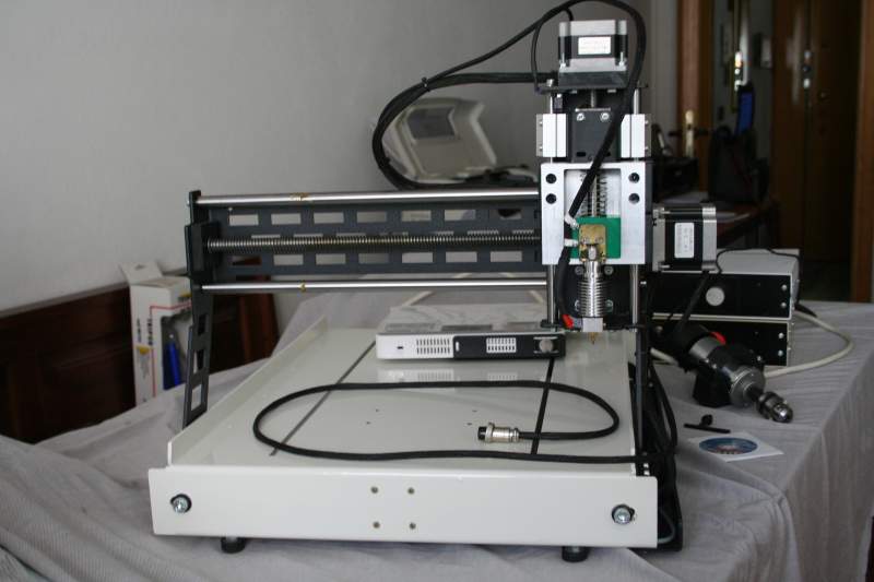
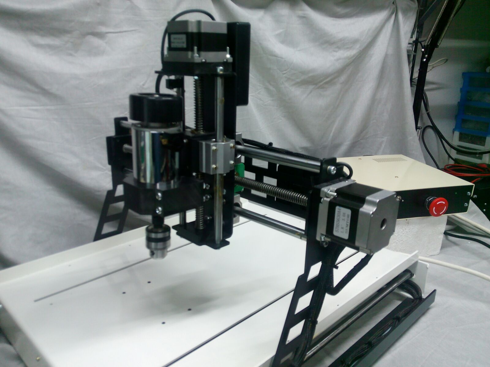

Scrivete a Fabio per consigli, per acquistare insieme componenti o per farvi procurare da lui dei kit di componenti. Oppure potreste anche accordarvi per costruire delle parti o delle macchine complete.
Fabio di Arezzo – Civitella in Val di Chiana (AR) – fabio.cve31@gmail.com
Aggiungo qui alcune nuove immagini che ci ha mandato nel 2024 e anche un manuale in PDF
Radar e bracci robotici

Questo è il primo sonar di Mauro Riboni, l’applicazione ThereminoRadar è nata da questo prototipo. Ringraziamo ancora Mauro, per averci coinvolto e per aver insistito, fino a farlo funzionare.
Download del ThereminoRadar qui: /downloads/automation#radar e informazioni sui sensori qui: /hardware/inputs/sensors#usound
– – – – – – –

Mauro Riboni sta anche sperimentando diverse versioni di bracci meccanici. Le sue meccaniche sono studiate e realizzate molto bene. Questa è una versione con servo di grande potenza. Questi servo non sono adatti per scrivere a causa della loro dead band, ma sono ottimi per prendere e sollevare oggetti. I due servo alla base e la costruzione molto robusta, permettono di sollevare oggetti abbastanza pesanti.
– – – – – – –

Uno dei primi prototipi di ThereminoArm. Questa versione usava ancora un Master e uno Slave, perché i primi Master non avevano PIN configurabili. Ora si fa tutto con il solo Master e avanzano anche due PIN. Aggiornamento dell’aprile 2017: il nuovo firmware dei Master, aumenta il numero di PIN da 6 a 12, quindi ora avanzano ben otto PIN per usi generici. Inoltre i nuovi firmware possono pilotare anche i motori stepper.
Si possono quindi costruire bracci robotici molto precisi utilizzando piccoli motori stepper e cinghie dentate. Si consiglia di usare un rapporto di demoltiplicazione molto alto, almeno cinque ma meglio se si riesce ad arrivare a dieci. In questo modo i 200 passi per giro diventeranno 2000 passi per giro e si potrà ottenere una precisione di 0.7 mm con bracci lunghi mezzo metro. Precisione che aumenterà a circa un decimo di mm e oltre utilizzando i microstep.
– – – – – – –
Un Robot non è necessariamente un braccio articolato. Con un po’ di fantasia, si possono comporre macchine semplicissime ed efficaci.

Un robot “didattico” costruito dagli allievi dell’istituto I.C. di Corniglio
La motivazione proposta dell’istituto I.C. di Corniglio è: “…ricongiungere il mondo digitale col mondo reale e concreto” ed è proprio per questo che è nato il sistema Theremino. Un caloroso grazie per le vostre ricerche!
Sketch e Firmware
Molti dopo aver imparato il linguaggio sketch di Arduino, ci hanno scritto che vorrebbero usarlo, anche per Theremino. Purtroppo il linguaggio sketch è stato pensato, solo per i processori dell’Arduino e trapiantandolo su altri “micro”, diventerebbe così diverso, da perdere ogni possibilità, di scambiare i programmi tra i due.
I nostri PIC si programmano in C o in C++, usando un IDE standard e compilatori standard, noi usiamo il GNU Compiler, che è Open Source.
Per quanto la enorme popolarità di Arduino, possa farci apparire “diversi”, in realtà è vero proprio il contrario, è Arduino che usa un linguaggio non standard, fatto apposta per Arduino e valido solo per Arduino.
Gli sketch non sono vera programmazione del firmware, ma una programmazione semplificata, che nasconde tutto il “contorno”. Con gli sketch, l’efficienza è le possibilità di manovra, sono limitate.
Inoltre gli sketch provocano una deformazione didattica, si impara a usare una astrazione del micro, al posto del micro stesso. Per imparare a usare un micro, si dovrebbero studiare i data-sheet del costruttore, non le istruzioni di Arduino.
Detto questo, per fortuna, il firmware del sistema Theremino, non richiede programmazione. Siamo nel 20xx e si suppone che gli InOut di un PC, così come il firmware di un telefonino, o di una lavatrice, siano funzionanti “come sono”, senza doverli ri-programmare ogni volta, a seconda che si vogliano lavare camicie, oppure blue jeans.
Spostamento di prospettiva
Lo spostamento di prospettiva, tra Arduino e Theremino è di fatto, spostare l’intelligenza dal firmware al software. Questo spostamento moltiplica per mille la velocità disponibile, la potenza di calcolo, la memoria, e la facilità di programmazione.
Per questo approccio, si deve essere costantemente collegati a un PC (o un NetBook, un eeeBox, un Tablet, un MiniPC o un Raspberry Pi, come spiegato qui: blog/standalone-applications#standalone, e anche qui: downloads/notes-on-software#computers)
Molti dispositivi, come le stampanti, i monitor e i mouse, sono costantemente collegati al PC e tutti lo trovano “normale”. Eppure molti pensano che un “dispositivo”, come ad esempio un braccio robotico, o una stampante 3D, dovrebbero essere autonomi, e probabilmente anche a pile…
Bracci robotici e intelligenza
Facciamo l’esempio, guarda caso, di un “braccio robotico”. Molti costruttori di bracci robotici Arduinici, si sono accorti che il loro braccio “autonomo a pile”, alla fine fa sempre la stessa cosa. Cosa gli manca? La comunicazione e il software, algoritmi potenti che tengono in contatto i dati 3D, con il mondo esterno, sensori, WebCams, microfoni, capire i GCode, e comunicare con altre applicazioni, in tempo reale.
I micro non sono concepiti per gestire file 3D, o decodificare segnali audio, non hanno potenza adeguata, per suonare file midi, o decodificare il video di una WebCam. E se anche li si costringe a farlo, lo fanno male. Detto con altre parole: “Il luogo adatto per il cervello, non è vicino ai muscoli”
Un altro motivo, che rende molto furbo, collegare stabilmente bracci e stampanti 3D al PC, è che si deve fornirli di alimentazione. Quando si supera la fase giocattolo, le esigenze di alimentazione, diventano troppo pesanti, per le pile.
Come sono fatti i bracci robotici professionali ?
- Hanno grossi cavi, che portano alimentazione e dati.
- Comunicano costantemente con un PC di controllo.
- Contengono solo il firmware, gli algoritmi intelligenti, sono tutti sul PC.

Fate click sulla immagine, per vedere meglio.
Quale linguaggio usare?
Una volta deciso di spostare l’intelligenza, dal firmware verso un linguaggio ad alto livello, quale è il migliore linguaggio da imparare?
Qui è una questione di gusti, alcuni dicono che esiste solo il C++, e trattano con disprezzo, ogni altro linguaggio.
Altri, come noi, pensano che il C++ sia ormai un linguaggio vecchiotto, che richiede molto più tempo e energie, dei linguaggi recenti. E pensano anche che C++ e simili (C, Java e tutti i linguaggi con il punto e virgola a ogni riga) siano linguaggi mal strutturati e poco formali, che invogliano a scrivere, in modo “sporco” e confuso. In questi linguaggi è possibile scrivere, cose accettabili dal compilatore, ma assolutamente illeggibili, per gli umani.
Noi preferiamo linguaggi più strutturati, che aiutano a scrivere bene, e a minimizzare gli errori. Questo processo di allontanamento graduale, dal linguaggio macchina, è in atto da cinquant’anni e ad ogni nuovo passo, c’è chi si lamenta e rimpiange i vecchi linguaggi. Ma il processo proseguirà, e alla fine arriveremo a programmare, in linguaggio umano. Attualmente il linguaggio più umano è VbNet.
Come contorno i linguaggi moderni (VbNet e C#), hanno una potenza e una velocità di esecuzione impressionante, perché le loro funzioni di base, non vengono riscritte ogni volta da zero, ma sono invece pronte nel “RunTime” e scritte con algoritmi ottimizzati, e adattati al sistema operativo.
Un secondo vantaggio dei linguaggi moderni, è di essere indipendenti dal sistema operativo. Una applicazione scritta in C# o in VbNet, gira senza cambiare una virgola anche su Mac, Linux e Unix. (questo almeno in teoria… in pratica solo su Windows funziona tutto bene, mentre sugli altri sistemi operativi, le implementazioni sono incomplete e piene di errori)
Concludendo noi suggeriamo di usare VbNet oppure C# (molto simili tra loro) Quasi tutte le applicazioni, del sistema Theremino, sono scritte in VbNet, perché lo troviamo più “umano”, ma si può facilmente passare da un linguaggio all’altro, usando SharpDevelop per tradurre.
Per installare gli strumenti di sviluppo, leggere qui: downloads/notes-on-software#instruments
Buongiorno a voi.
Ho acquistato una scheda Theremino StepperDriver che servirà a sostituire l’elettronica orginale di una cnc cinese che utilizzo per produrre PCB. Ho visto che la suddetta scheda può gestire oltre ai motori anche 2 linee di potenza con mosfet, quindi immagino che ci si possa collegare anche un elettromandrino. Non ho trovato però istruzioni dettagliate su quali siano le porte per gestirlo e dalle immagini che trovo in rete, mi rimane qualche dubbio. Sapete anche se esiste un pdf con tutte le info per la schedaStepperDriver?
Ringrazio anticipatamente per la vostra risposta.
Solitamente i mandrini funzionano a tensione di rete, quindi i mosfet di questa scheda non possono pilotarli. Questi Mosfet sono pensati per regolare in PWM le resistenze di riscaldamento delle stampanti 3D.
Per accendere e spegnere il mandrino dovresti utilizzare un relè meccanico o il nostro OptoTriac (ma attenzione alla potenza sopportabile e al raffreddamento del Triac). Per regolare il mandrino in velocità dovresti inviargli il Pwm da una uscita del Master e avere una adattatore Pwm che regga la potenza. Oppure il mandrino stesso dovrebbe accettare un segnale Pwm.
La scheda Stepper Driver è spiegata in questa pagina:
https://www.theremino.com/hardware/adapters
I Pin e gli Slot da utilizzare sono spiegati nella documentazione della applicazione CNC (gli Slot da usare sono a pagina 43).
Per i concetti generali sul funzionamento degli Slot dovresti anche leggere la documentazione della applicazione HAL e dei moduli Master.
—-
Se ti serve altro chiedi, ma spiega nei particolari quello che non ti è chiaro, così potremo concentrarci su quello che ti serve.
Qualche tempo fa ho chiesto consigli a Livio su come produrre un gcode per Theremino CNC con Eagle e Fastgcode.ulp. Se ricordi il gcode prodotto si limitava alle forature del circuito “stampato” e non disegnava le piste. Avevo fatto anche degli screenshot della pagina di configurazione di Fastgcode per farmi aiutare. Alla fine avevo rinunciato per questioni di tempo e avevo usato un altro software per il gcode. Ieri, però, ho finalmente risolto il mio problema e tutto funziona perfettamente con il tuo Fastgcode 7.9, era necessario impostare almeno due step di profondità sull’asse Z, in una qualunque delle caselle (io l’ho fatto per la fresatura del contorno della board). Grazie ancora per la tua disponibilità
Grazie per le tue prove.
FastGcode è una applicazione poco usata e alcune operazioni sono difficili da capire o anche difettose.
E’ consigliabile provare anche le versioni precedenti, che non avevano la foratura per prima. Le ultime versioni, con la foratura all’inizio, sono state provate poco e potrebbero avere dei difetti.
Buongiorno,sono ormai tre anni che utilizzo theremino master per far funzionare una fresatrice a tre assi per legno con ottimi risultati. Ora ho provato a guidare una torcia al plasma per il taglio dei metalli ma ho subito incontrato delle difficoltà perchè quando si accende la torcia molte volte si interrompe la comunicazione usb e HAL va in errore. Sto usando un taglio plasma economico con accensione a contatto perchè macchine studiate per il cnc costano migliaia di euro. Ho preso un cavo usb schermato ma non ho migliorato di molto le cose. Volevo sapere se ci sono dei filtri o delle protezione per impedire le interferenze elettromagnetiche. La partenza del taglio è gestita da un pin del master che attiva un SSR che a suo volta attiva un relè elettromeccanico a 220 volt che chiude il circuito del tasto di partenza sulla torcia(ho fatto cosi’ per utilizzare le uscite a 220 volt comandate dal master per aspiratore e mandrino).
Grazie , Luca Aste
Non è il cavo USB a raccogliere disturbi, ma i fili che vanno dal Master verso i driver dei motori Stepper e verso i sensori (pulsanti manuali e finecorsa).
Scollega dal Master tutti i fili (proprio dalla schedina del Master non dall’altro lato).
E scollega anche i fili di massa che vanno ai driver e ai sensori.
Il Master quindi sarà collegato solo alla USB.
Controlla anche di avere la massa del PC collegata alla terra dell’impianto elettrico.
In queste condizioni prova ad accendere e spegnere la torcia più volte e la comunicazione non dovrebbe mai staccarsi.
Poi collega solo uno dei sensori e riprova
Poi collega solo un motore stepper e riprova.
Una volta individuato da quale filo (o da quali fili) i disturbi arrivano al Master, ci concentreremo su di lui e aggiungeremo dei resistori per eliminare completamente il problema.
Per i finecorsa e i pulsanti manuali i disturbi si eliminano completamente aggiungendo due resistori come spiegato qui:
https://www.theremino.com/technical/communications#pullup
Se invece i disturbi arrivano dai driver degli Stepper, allora vanno collegati alla terra dell’impianto elettrico anche i negativi degli alimentatori dei driver degli stepper.
Grazie, farò queste prove e poi vi dico!
Finalmente ho potuto fare le prove. Dalle informazioni che ho trovato il sistema di accensione non è ad alta frequenza ma ha una bobina che manda delle scariche ad alto voltaggio(un po’ come un vecchio accendigas). Ho staccato tutto dal master ma,facendo partire l’accensione dopo due tre volte salta la comunicazione usb e si interrompe il programma cnc. Ho collegato la terra del banco di taglio al centro delle terre dell’impianto (facendo memoria dei consigli sulla messa a terra)ma il problema si è ripresentato. Ho fatto funzionare il plasma in una stanza vicina sotto un’ altra linea ma,se mi avvicino a un metro dal computer e faccio partire l’accensione,salta di nuovo la comunicazione. Se invece metto la tagliatrice vicino al computer ma sto lontano con la torcia allora posso accendere quanto voglio e non c’è nessuna interferenza.Poi ho notato che posso avvicinarmi con la torcia al computer facendo funzionare l’accensione senza provocare interruzioni solo se tengo nelle vicinanze del cavo della torcia quello della massa che si attacca al metallo da tagliare(?!!) Questo mi farebbe pensare che magari mettendo uno schermo in rame al cavo torcia e collegandolo a terra potrebbero migliorare le cose…. Cosa ne pensi?Grazie , Luca
Dato che parli di alta tensione, immagino che la corrente che passa lungo il cavo della torcia sia molto piccola, quindi schermi elettrici (alluminio o rame sottile) dovrebbero schermare totalmente i disturbi.
Quindi potresti provare ad avvolgere il cavo della torcia con un foglio di alluminio da cucina (almeno per prova, poi se funziona potresti studiare di meglio).
All’inizio del cavo della torcia dovresti avvolgere, attorno all’alluminio, un po’ di spire di filo nudo e poi collegare questo filo alla terra.
Poi forse dovresti anche schermare la torcia stessa.
Controlla poi anche che la scatola da cui esce il cavo sia metallica e messa a terra. Prova con il tester, non ti fidare. Dopo molti anni che lo usavo, ho scoperto che il mio alimentatore da banco, aveva la scatola non collegata a terra. E infatti tutte le volte che lo accendevo e spegnevo generava disturbi. Gli ho spellato la vernice sotto la vite di messa a terra ed è andato a posto.
Se non funziona allora ci sono accoppiamenti magnetici, ad esempio tra il trasformatore che genera l’alta tensione (che però dovrebbe essere fatto malissimo e avere normi perdite), e il cavo USB.
Sono abbastanza stupito che sia possibile far perdere la comunicazione al Master nudo, senza alcun filo collegato ai Pin. Magari riprova ma con il cavo USB non disteso (tutto ammucchiato a “S”, vicino al PC e con il Master sopra). In questo modo verificherai se è il cavo USB a captare il disturbo.
Prosegui con le prove, solo tu procedendo passo-passo e con metodo, come hai fatto finora, potrai capire cosa succede. E, per piacere, quando avrai ben capito cosa si accoppia e dove, scrivilo qui. Che sono davvero curioso di capire come succede.
Grazie per l’idea dello schermo. Controllerò anche la messa a terra della scatola del plasma che è metallica.Poi ti farò sapere. Ho visto anche l’aggiornamento per la protezione ai pin di input con il condensatore oltre che i due resistori. Proverò anche quello in quanto la sola protezione con i resistori non era sufficiente e avevo dovuto staccare tutti i finecorsa perche’ mi si interrompeva la comunicazione usb (anche solo con la fresa)
Avevi messo il resistore di protezione da 330k vicino al Master ?
Se è così allora hai dei disturbi indotti sui fili veramente enormi, centinaia di volt. Se capita con tutto messo a terra, allora c’è qualcosa di molto strano e dovresti scoprire cosa è.
Finalmente son riuscito a fare nuove prove con il plasma. Ho aggiunto uno schermo in maglia di rame sul cavo torcia ,ho aggiunto un filtro emi in entrata sul taglio plasma e uno sull’alimentazione computer-controllo ,ho fatto partire un gcode e ho continuato a innescare l’arco plasma e tutto funziona!
Leo ci ha chiesto
Nella applicazione HAL le regolazioni dei motori stepper sono in “mm al minuto”, “mm al secondo per secondo” e “Steps per mm”. Questo mi rende difficile fare i calcoli quando invece che millimetri voglio usare i giri del motore, oppure i gradi.
Risposta
Abbiamo utilizzato i millimetri perché la maggioranza dei lettori ha un motore stepper che ogni giro muove una fresa di un millimetro, oppure di due millimetri. Per cui in questi casi diventa facile fare i conti.
– Il motore ha 200 passi per giro
– Se ogni giro fa un millimetro allora sono 200 step per mm
Poi da qui si derivano facilmente gli altri casi:
– Se ogni giro facesse due mm allora sarebbero solo 100 step per mm
– Se poi regolassi il driver con i microstep per 8, allora sarebbero 800 passi per mm.
In alcuni casi (raramente) potrebbe essere utile ragionare in unità di misura diverse dal mm. Ad esempio in pollici, o in gradi, oppure in giri del motore. In questi casi basterà sostituire mm con la nuova unità e procedere sempre nello stesso modo.
Volendo si potrebbe anche aprire il file della lingua che si usa e cambiare il testo che si vuole far apparire in Label_MaxSpeed, Label_MaxAcc e Label_StepsPerMillim. Non consigliamo di fare questo perché è scomodo e perché non è nemmeno detto che si vogliano tutti i motori con la stessa unità di misura.
Per cui semplicemente dove c’è scritto “mm”, fate conto che ci sia scritto “metri”, “gradi”, “pollici”, “giri”, o qualunque altra unità di misura lineare o circolare.
Attenzione però che quando poi si invieranno dati al motore dovranno essere nella stessa unità che si è utilizzata per scrivere nelle caselle dell’HAL.
——————-
Tanto per fare due esempi ecco come si fanno i conti, ragionando in giri motore o in gradi al posto che in mm.
I prossimi due esempi rispondono alla domanda:
“Considerando che il Master ha una massima frequenza di emissione degli Step di 65 Khz”
“E considerando di avere un driver del motore regolato per 256 microstep”
“Quale è la velocità massima del perno di uscita del motore, in gradi e in giri al minuto?”
—————————————————————————————————–
Max Speed in “degree”
(for a stepper motor with 200 step per tourn and 256 microsteps)
—————————————————————————————————–
Motor = 200 steps / tourn
Motor with microsteps = 200 x 256 = 51200 steps / tourn
The same in degree = 51200 / 360 = 142.22 steps / degree
Master max pulse frequency = 65500 pulses per second
Motor max speed = 65500 / 142.22 = 461 degree / sec (approx)
Motor max speed = 461 x 60 sec = 27660 degree / min (approx)
—————————————————————————————————–
Max Speed in “tourns”
(for a stepper motor with 200 step per tourn and 256 microsteps)
—————————————————————————————————–
Motor = 200 steps / tourn
Motor with microsteps = 200 x 256 = 51200 steps / tourn
Master max pulse frequency = 65500 pulses per second
Motor max speed = 65500 / 51200 = 1.28 tourns / sec (approx)
Motor max speed = 1.28 x 60 sec = 76.8 tourns / min (approx)
Sono Luca : sulla mia fresatrice controllata dal master volevo avere la possibilità di far partire il motore mandrino, collegato attraverso un ssr ad un pin di uscita, anche manualmente attraverso un tasto per fare delle lavorazioni con spostamenti in manuale. Se io collegassi questo tasto ad un alimentatore separato e all’entrata dello stesso ssr provocherei delle interferenze con il master?
Aggiungi un resistore da 10k in serie alla uscita del Master e poi collegandoti al lato opposto (che va verso il comando del motore) puoi fare quel che vuoi. Suppongo però che il pilotaggio del comando motore sia ad alta impedenza, se non lo fosse dovrai abbassare il resistore un po’, magari a 1k.
Oppure dovresti aggiungere due diodi.
Difficile consigliarti meglio senza conoscere i componenti e che usi e come li colleghi.
Salve Livio, ti chiedo alcune informazioni in merito al pilotaggio di stepper e di brushless.
1) per pilotare un singolo motore stepper, ad esempio un posizionato re, come potrei fare? Devo per forza usare Theremino CNC? in che modo potrei inviare un comando?
2) Sono in possesso di un grosso motore brushless, poiche’ è un servo devo sempre usare oltre al driver (tipo Turnigy per intendersi) anche la scheda servo vero?
3) in tal caso dove posso acquistarla? Non mi sembra di averla vista su store-ino.
Grazie ancora di tutto
1) Per pilotare uno STEPPER devi utilizzare il modulo Master e la applicazione HAL. Poi con qualunque applicazione scrivi un valore di destinazione in millimetri (o gradi di rotazione) nello Slot relativo, e lo stepper accelera fino alla massima velocità che hai impostato nell’HAL, poi rallenta e si ferma alla destinazione stabilita. Potresti impostare le destinazioni, e cambiarle anche mentre il motore si muove, scrivendo qualche riga nella applicazione Theremino_Automation.
2) I motori BRUSHLESS si pilotano con la scheda ESC (ad esempio Turnigy) e con il modulo Master. Poi devi aprire l’HAL e impostare l’uscita come Servo 16. Infine lo muoverai cambiando il numero nel suo Slot da 0 a 1000.
3) Non devi usare una scheda “servo” ma un modulo Master. Il Master lo trovi sia su eBay (venditore maxtheremino), che su STORE-INO
Grazie infinite…. Chiarissimo come sempre.
Buon lavoro
Ciao sono Luca. Volevo usare per azzeramento assi dei sensori induttivi. Che tipo di sensore devo prendere NPN o PNP? Ho visto che si alimentano con tensioni da 6 a 30 volt e quindi penso che il collegamento ai pin non sia immediato… Volevo sapere se sul sito esiste uno schema su come collegare questo tipo di sensori. Grazie
Potresti usare sensori magnetici (elementi di HALL) e calamitine.
Ce ne sono che vanno anche a 3.3 volt, ad esempio:
– A1319
– A1318
– A1318
– DRV5056
– DRV5055
Ce ne sono anche altri che vanno a 5 volt ma poi potrebbero superare con il segnale i 3.3 volt degli ingressi del Master e quidi dovresti aggiungergli un resistore in serie da 33k o un partitore. Eccoli:
A1321
A1322
A1323
A1301
A1302
In realtà anche se fatti per 5 volt vanno bene anche se li alimenti con il 3.3 volt del Master.
—————
Oppure Dovresti scrivere la sigla dei sensori che vuoi usare, potremmo indagare un po’ e molto probabilmente funzionano anche alimentandoli 5 volt. Oppure ne cerchi qualcuno che vada a 5 volt, ci sono di sicuro.
Grazie.Sempre preciso e velocissimo.
Luca
Ciao,sono Luca. Ho preso dei sensori di Hall per Arduino e funzionano anche alimentandoli col 3.3 Volt. Il mio problema è come collegare fra loro i due sensori per azzerare gli assi x e y il cui azzeramento viene fatto in un unica operazione. Lo slot per l’azzeramento è il 33 ma posso attribuirlo solo ad un pin.
Grazie Luca
Ci vogliono due diodi 1N4148 e un resistore da 10k, da posizionare tutti vicino al Master.
I diodi vanno in serie ai segnali dei due sensori e si uniscono sull’ingresso del PIN associato allo Slot 33, configurato come DigIn.
Poi devi capire se i segnali dei sensori vanno a zero volt quando arrivi a fondo corsa, oppure se vanno a 3.3 volt.
SE VANNO A ZERO VOLT
– Le fascette dei due diodi vanno girate verso i sensori
– Il resistore va collegato tra l’ingresso del PIN e il +3.3 volt (oppure potresti configurare l’ingresso come DigIn_PU e eliminare il resistore).
SE VANNO A 3.3 VOLT
– Le fascette dei due diodi vanno girate verso il punto di unione che va al PIN
– Il resistore va collegato tra l’ingresso del PIN e GND
– Il segnale dello Slot 33 va invertito scambiando i valori delle sue caselle MaxValue e MinValue sull’HAL (MaxValue = 0 e MinValue = 1000)
Se non riesci scrivi ancora qui, oppure chiama con skype o telefono.
Grazie,mi procuro i diodi e provo
Ciao,ho fatto i collegamenti ma penso di avere dei problemi con il tipo di sensore,nel senso che il sensore non scatta in modo “pulito” ma fa oscillare il valore del pin acceso-spento ingannando cosi la procedura di azzeramento. Ho usato l’ uscita digitale del sensore ma fa lo stesso così… il sensore è questo
https://images-na.ssl-images-amazon.com/images/I/71wrd7sc2QL._SL1500_.jpg
Controllando il voltaggio di uscita il valore cambia mano a mano che la calamita si avvicina al punto centrale
Se usi un ingresso DigIN dovrebbe funzionare e scattare a 1000 (o a zero) quando ti avvicini oltre un certo punto. E la procedura della applicazione CNC una volta che lo ha sentito dovrebbe fermarsi.
Forse stai lavorando al contrario. Verifica (con lo SlotViewer) che il segnale dello Slot 33 vado a zero quando vai a fondo corsa sia con un asse che con l’altro, e che torni a 1000 quando li allontani ambedue dal fondo corsa.
Dovresti anche cercare di ottenere scatti precisi, cambiando la disposizione delle calamite e dei sensori.
E dovresti anche evitare di andare a sbattere sui sensori se il carrello non si ferma subito. Per ottenere questo dovresti non farli lavorare in avvicinamento ma di lato.
E dovresti anche ruotare il magnetino nella posizione migliore e alla distanza migliore, fino a che la commutazione è buona e ben ripetibile. Muovendo il carrello a mano a motori spenti, o con il JOG del CNC, e guardando il segnale con lo SlotViewer o il SignalScope.
Ho rinunciato ai sensori di hall perchè ho difficoltà a regolarli.Pensavo di usare dei sensori meccanici come quelli che ho messo per i finecorsa. Li ho collegati normalmente aperti in parallelo su un pin configurato dig in che scrive sullo slot 33 impostando val min 1000 val max 0 ma quando il sensore va a contatto non si ferma( solo riaprendo manualmente il contatto scatta la calibrazione). La sequenza di calibrazione avverrebbe in maniera corretta mettendo val max 1000 e val min 0 ma in questo caso facendo partire la calibrazione i carrelli vanno verso valori positivi( ho fatto questa prova facendo scattare manualmente i sensori).Luca
Scusa tanto. Ho riprovato adesso e tutto funziona.Non so che pasticcio avevo combinato prima .Spero di non averti fatto perdere tempo. Grazie. Luca
ciao Livio
vorrei chiederti se c’è il modo di poter controllare i motori passo passo per una cnc tramite theremino cnc e master usando però come driver gli l298n, che hanno bisogno di 4 ingressi per comandare i motori invece dei soli step e dir. ti chiedo questo in quanto ho diversi driver di questo tipo avanzati e li volevo sfruttare per fare prove sugli stepper.
grazie
Fabrizio
No, mi spiace, ma gli L298N sono fatti per motori in continua e non possono pilotare i motori Stepper.
Ok, chiedevo perché con Arduino si riesce a pilotarlo però usando appunto 4 pin… Li vendono anche per stepper fino a 2a ma in effetti mancando il complementare l298 è difficile pilotarlo.
Grazie della veloce risposta come sempre.
Fabrizio
Il problema non è pilotarlo, che forse in qualche modo si potrebbe anche fare, ma che quel modulo non lo puoi collegare a un motore stepper. Quel modulo è un Ponte-H e serve per pilotare motori in continua, non motori stepper.
—————-
AGGIORNAMENTO
Sono andato a vedere meglio e in effetti a quel modulo puoi anche collegare i motori passo-passo ma usandoli come se fossero dei motori in continua, cioè regolandoli in velocità e direzione ma NON in posizione.
Copio dalle caratteristiche del modulo:
“Questa scheda controllo motori è basata sul driver Dual H-Bridge L298N e permette di pilotare con semplicità due motori DC oppure un motore passo-passo bipolare con tensione operativa compresa nel range tra 5V e 35V, controllandone la velocità e la direzione.”
In pratica con quelle schede un motore passo passo ti girerebbe a velocità regolabile, ma perderesti la caratteristica principale dei motori passo-passo, cioè la possibilità di sapere sempre quanti passi hai fatto e quindi la posizione esatta. E senza la posizione esatta le macchine CNC non possono funzionare.
Spiegazione come sempre impeccabile! Grazie!
Lasciando quindi da parte il controllo cnc per questi driver, volendo usare esclusivamente per provare un motore passo passo, nello specifico per fare prove di forza torcente (la classica prova col peso attaccato per arrivare a testare la forza reale del motore a determinata tensione e corrente o anche solo per capire se un motore funziona o meno), sarebbe complicato farli girare col modulo master o è una cosa semplice da poter fare senza smanettarci una giornata?
La mia idea di base era capire se si poteva far fare al modulo il lavoro che nei driver appositi svolge l’integrato l297, che prende appunto dei segnali dir e step e li gestisce per poter pilotare il ponte h l298…
Questi piccoli driver economicissimi sono molto diffusi e magari può interessare anche ad altri usarli con quest scopi, non so.
Grazie ancora della disponibilità
Fabrizio
“Questi piccoli driver economicissimi…”
Non mi sembra proprio così, esistono driver per stepper che costano più o meno come gli L298.
E spendendo appena un po’ di più ci sono driver per stepper da 4 ampere che in confronto gli L298 sono delle ciofeche, guarda questo ad esempio:
https://tinyurl.com/qtp8kd5
Nella prossima mail ti scrivo come collegarli al Master, anche se quello che potrai ottenere è una schifezza rispetto a un vero stepper driver.
vero, infatti anche io uso sulla mia cnc il driver 4 assi tb6560, che sostituisco adesso sulla nuova cnc coi tb6600, ma la prima che ho fatto avevo usato la coppia l297/l298
Il fatto è che questi li avevo presi molto tempo fa a corredo di altro materiale pagandoli tipo 1,5€ l’uno, ne presi una dozzina da tenere li…certo non li consiglierei neanche io per le cnc, hai perfettamente ragione
Per pilotare gli L298N dicono…
Enabling pin 6, if we give logic as:
Pin5=high, pin7 = low, motor A will start turning clockwise.
Pin5=low, pin7 = high, motor A will start turning anticlockwise
Pin5=high, pin7 = high, motor A will stop
Pin5=low, pin7 = low, motor A will stop
Enabling pin 11, if we give logic as:
Pin10=high, pin12 = low, motor B will start turning clockwise
Pin10=low, pin12 = high, motor B will start turning anticlockwise
Pin10=high, pin12 = high, motor B will stop
Pin10=low, pin12 = low, motor B will stop
Quindi per pilotarli con un Master dovresti:
– Abilitare il Pin 6 dello L298N con un Pin di uscita del Master
– Utilizzare un Pin di uscita del Master collegato al Pin 5 dello L298N per stabilire la direzione
– Utilizzare un Pin di uscita del Master collegato al Pin 7 dello L298N per farlo girare (con il PWM cambierai la velocità)
– Abilitare il Pin 11 dello L298N con un Pin di uscita del Master
– Utilizzare un Pin di uscita del Master collegato al Pin 10 dello L298N per stabilire la direzione
– Utilizzare un Pin di uscita del Master collegato al Pin 12 dello L298N per farlo girare (con il PWM cambierai la velocità)
Poi il tutto non sarebbe controllabile dalla applicazione CNC, ma ti ci vorrebbe un software apposito per alzare e abbassare i sei Pin di uscita del Master nelle giuste combinazioni.
Come vedi il tutto diventerebbe estremamente complesso e impegnerebbe ben sei pin del Master quando con un normale driver ne bastano due. E alla fine nemmeno avresti il controllo della posizione.
Per cui non ci perderei del tempo.
Ok, capito, mi fido della tua opinione. Lascio perdere e semmai li uso, giusto per provare i motori, con Arduino semplicemente facendogli fare movimenti preimpostati nello sketch. Grazie ancora
Fabrizio
Ciao Livio e buona pasqua a tutto lo staff.
domanda: è possibile (nel programma di cnc sorgente) modificare il ritorno di un millimetro dall’azzeramento automatico del asse z ?
Mi sono fatto un azzeratore ottico che sbaglia di qualche millesimo a tastatura..Con una stampante 3d a resina e un sensore ottico .
il problema è che il ritorno mi servirebbe più lungo visto la corsa che ho del tastatore.
eventualmente dove dovrei modificare questa funzione con visual espress?
P.S nella programmazione mi aiuta un mio amico…in tutto il resto mi arrangio.arrriciao a tutti e grazie
Ciao, dovresti premere il pulsante “Settings” (l’ultimo in basso a destra) e poi modificare il valore “Compensation (mm)” del pannello “Calibrate Z”.
Se questo non risolve il problema, scrivici un altro messaggio spiegando meglio cosa ti manca.
Oppure puoi modificare il software a tuo piacere con il Visual Studio 2008 Express, ma non sarà facile perché la applicazione CNC è molto complessa.
la compensazione la uso per azzerare il zero pezzo rispetto all’azzeratore fisso;faccio lo zero con compensazione mm 0 sul tastatore-asse z tocca e ritorna di “1 mm” e mi da misura a 1 mm.(-vorrei poter aumentare quel ritorno a (es 10 mm) e mi dà misura 10.-questo perchè la corsa del testatore è +- 10 mm, e se sposto subito gli assi x y mi raschia l’utensile sul tastatore).poi vado a toccare il pezzo,leggo la misura,la scrivo nella compensazione e il gioco è fatto…ogni volta che cambio l’utensile e vado a tastarlo, poi va sempre allo zero effettivo del pezzo, indifferentemente dalla lunghezza dell utensile.
se mi dai una dritta di dove posso modificare quel mm di ritorno,provo a modificare con visual basic. grazieeee livio
Non ho la minima idea di come fare a modificare il software per seguire quello che ti serve, anche perché non riesco a capire cosa ti servirebbe.
Hai provato a premere il pulsante “Settings” (l’ultimo in basso a destra) e poi modificare il valore “Compensation (mm)” del pannello “Calibrate Z”?
Facendo come ti ho scritto non funziona?
si,funziona, mi modifica ” l’offset dello zero pezzo correttamente” ma quando l’utensile tocca il sensore, si retrae di un millimetro… quel millimetro vorrei modificarlo a 10 millimetri
preciso che la compensazione la faccio in negativo+ 1 mm( quello che si ritrae dopo la tastatura
La variabile che ti serve è “CNC_CalFinalClearance”
e viene dichiarata e inizializzata nel modulo “Module_CNC” alla linea 173
Ecco come è scritta:
Friend CNC_CalFinalClearance As Single = 1 ‘ final movement fixed = 1 mm
Se la cambi con 10 si sposterà di 10 mm.
Peccato però che la variabile sia utilizzata anche per X, Y, A e B che si sposteranno anche loro di dieci mm dal sensore di azzeramento.
Se non ti va bene allora dovresti dichiarare una variabile specifica per l’asse Z subito dopo all’altra, come da esempio seguente:
Friend CNC_CalFinalClearance As Single = 1 ‘ final movement fixed = 1 mm
Friend CNC_CalFinalClearanceZ As Single = 10 ‘ final movement fixed for Z axis = 10 mm
E poi sostituirla in due linee nel modulo “Module_ExecutionThread”
– La linea 546 che diventerà così
CNC_Dest.z += CNC_CalFinalClearanceZ * CalZDirectionPositiveNegative()
– La linea 650 che diventerà così
CNC_Tip.z = CNC_CalZCompensation + CNC_CalFinalClearanceZ
Se non riuscite scrivici di nuovo
GRAZIE LIVIO.. sei sempre una sicurezza.. ti invidio un bel pò ..quindi ti faccio sempre i miei complimenti.
ciao a tutto lo staf e grazie
perfetto.. ho cambiato tutte le linee che mi hai indicato e tutto funziona come previsto da te… grazieeeeee
https://photos.app.goo.gl/voag7H9UMXfKi6WD8
provo a mettere le foto del mio cnc
Belle foto grazie!
di niente Livio…che te ne pare, ho fatto bene a mettere tre master o me ne consigli uno?
Tre master non servono a niente, mettine uno solo.
grazie provvederò al più presto
ciaooooo
Buongiorno
Mi chiamo Alessandro grazie a voi mi sono immerso in questo mondo.
Sto usando theramino CNC con una fresa a 3 assi e mi trovo molto bene.
Adesso mi sarebbe piaciuto preovare a costruire un braccio robotico, ma noto che su Robot Arm1 l’area di lavoro massima e di 1000 x 500 mm.
Idem le impostazioni di LenZ sono limitati a 99 mm.
E possibile aumentare il campo di lavoro.
Ringrazio anticipatamente per la vostra cortese attenzione
Per andare oltre i 500 mm ci vorrebbero motori da oltre 500 euro l’uno, cioè questi:
https://www.zeroerr.cn/eRob/index.html
Con normali servo hai già dondolii esagerati a soli 30 cm. Imprecisioni di centimetri e dondolii con tendenza alle oscillazioni. Allungando ancora di poco i bracci il tutto va in oscillazione e non si ferma più.
Stiamo cercando motori adatti a prezzi ragionevoli e abbiamo anche cambiato completamente direzione, abbiamo eliminato totalmente i calcoli 3D e quindi anche l’applicazione RobotARM. Era troppo difficile regolare i parametri e se la userai te ne accorgerai da solo.
Per cui ora stiamo usando un sistema diverso, dare le posizioni manualmente, posizione per posizione, senza nessun parametro da regolare e senza calcoli 3D.
Quando avremo ottenuto risultati utili li pubblicheremo in questa pagina:
https://www.theremino.com/hardware/outputs/smart-motors
Nel video seguente puoi vedere gli esperimenti attuali di un braccio “Collaborativo” con SmartMotors FeeTech:
https://www.theremino.com/files/ThereminoCobotV1.mp4
La programmazione è notevolmente più semplice che con la applicazione RobotArm, non si devono più regolare i parametri e gli angoli del braccio (che era difficilissimo), ma in compenso non si può più seguire un GCode o disegnare, solo definire delle posizioni una dopo l’altra.
Comunque anche con questi motori la lunghezza massima del braccio non può andare oltre i 50 centimetri.
Stiamo cercando motori che possano fare di più senza costare cifre folli, se li troveremo li pubblicheremo nella pagina degli Smart Motors
Ma con motori passo passo e una riduzione di almeno 1:10 non si riesce ad ottenere qualcosa di un po’ più preciso.
Pensavo a 4 nema 34 con cinghie dentate in M5 per ridurre il gioco.
Quindi volessi aumentare i limiti di theremino Arm non si può.
Se usi degli stepper con cinghie allora qualcosa di più potrai fare, ma oltre un metro è praticamente impossibile perché gli stepper pesano molto e quelli che stanno sul gomito e sulla punta dovresti sollevarli con una leva esagerata. Dire “un metro” è facile ma prova a farlo e poi ti renderai conto di cosa è effettivamente un metro.
Quando lo avrai montato (e se riuscirà ad alzare il suo stesso peso) in due minuti ti cambieremo il limite massimo della casella MaxViewArea da 1000 mm a 10000 mm e della LenZ da 99 a 9999
Ok grazie
Ciao Livio, ho provato Theremino ImgGreyscaleToGcode.
La velocità del mandrino sembra essere fissa a 20000. Sarebbe comoda poterla impostare.
Poi la scriverei prima del M3 per dar tempo al mandrino di prendere velocità.
Saluti
Mi spiace ma non abbiamo tempo di modificare tutte le piccole applicazioni per particolari come questo. Ci sono apposta i sorgenti e chiunque potrebbe farlo.
Comunque per sistemare subito il tuo problema ti basta impostare “Speed locked” nella applicazione CNC e poi regolare la casella Speed come preferisci. Oppure editare il Gcode e cambiare il 20000 in quello che vuoi e poi risalvarlo (si può fare direttamente con la applicazione CNC in un attimo).
No problem ,così già fatto.
Può servire ad altri come aiuto.
Buonasera, un paio di anni fa ho costruito una piccola cnc 3 assi comandata da theremino.
Ora vorrei sostituire la fresa con un modulo laser. Come devo collegarlo al sistema?.
Posso utilizzare il driver tb6560 che comanda l’asse Z?
Per i moduli laser il driver dei motori stepper non ci vuole.
Devi solo:
– collegare GND del Master a GND del modulo laser
– collegare il segnale di uscita del PIN del master al segnale di accensione del laser
– configurare l’uscita del PIN usato come DigOut (acceso / spento)
– oppure come Pwm16 (per regolare la potenza)
Normalmente i laser funzionano con un segnale di comando da 3.3 come il nostro e possono anche funzionare in PWM però non è detto che siano tutti così.
Se hai dei dubbi chiedi al costruttore o cerca in internet che segnale vuole il tuo modulo laser.
Se hai dei dubbi di qualunque genere non collegarlo e non dare tensione, i laser di potenza costano molto e sono delicati. Possono rompersi in un microsecondo anche solo perché è giovedì e si sono svegliati male.
Ciao sono Luca. Ormai da quattro anni uso Theremino cnc con una fresa 3 assi piu’asse rotativo. Ho sempre aggiornato le versioni del software. Ho provato l’ultima versione 5.3 e va veramente molto bene anche sulle fresature circolari dove le versioni precedenti, soprattutto ad alta velocità, deviavano dal percorso impostato. Il problema che ho riscontrato è che se apro la schermata di Hal per fare degli aggiustamenti di velocità o accelerazione,non appena clicco sulla lista dei pin per entrare nel menù di regolazione sento i motori che fanno dei passi fantasma. E’ la prima volta che mi succede. Anche la schermata di Hal è un po’strana ,nel senso che presenta delle parti trasparenti che lasciano vedere la schermata di Thereminocnc. Uso Windows 7. Prima usavo la versione 5.0 ma ho dovuto mettere una versione precedente dell’ Hal perche’ avevo lo stesso problema.
Veramente strano, non abbiamo cambiato niente nell’HAL che possa fare queste cose.
Potresti chiamarmi su Skype (mi puoi cercare come livio_enrico) e lo vediamo insieme?
Oppure, se non usi Skype, scrivi di nuovo qui e ti manderò il mio telefono.
Ciao,non uso Skype,ma oggi sono riuscito a fare un video dove si vede il problema.Posso inviartelo via mail? Quello che ho notato (e che non succede con le versioni precedenti ) è che quando clicco sulla lista pin per aprire i pannelli di regolazione la Ripetizione fps si blocca (senza dare errore) e poi riparte ed è in quel momento li’ che il motore dell’asse su cui avevo cliccato fa dei passi. Grazie
Buonasera Livio,
mi presento, mi chiamo Davide Lorusso, vorrei farvi i complimenti per questo progetto!!!
Premetto che ho gia’ una cnc 3 assi e sono passato da un po’ da linux cnc al vostro sistema, ed ho applicato theremino automation in sostituzione di un vecchio plc telemecanique.
Sto realizzando un’automazione per il settore occhialeria, dovrei interfacciare un piccolo sistema cnc 3 assi con un sistema di affogatura cerniera (sembra complicato ma si tratta di due cilindri e un sistema di riscaldamento);
e’ possibile , dopo aver realizzato un’operazione di foratura o fresatura, far partire un ciclo automatico di lavoro (nel mio caso spostare la slitta in posizione di affogatura ed eseguirla)?
Grazie
Davide
Credo che dovresti usare gli assi A e B
Ci sarà meditare un po’ e fare varie prove.
Dovrei capire con cosa muovi la slitta (altri stepper ?)
Ma altri due motori (A e B) ti basteranno?
Se poi non riuscirai con la sola applicazione CNC abbiamo pronta una nuova versione di Theremino CNC (che pubblicheremo tra breve tempo) controllabile con comandi da altre applicazioni. Così potresti disporre di tutte le funzioni di un vero programma procedurale (Theremino Automation), leggere sensori, muovere altri motori, pilotare solenoidi, pronunciare messaggi, eseguire funzioni su comandi vocali, leggere Barcode o QRcode, eseguire temporizzazioni, loop, conteggi e controlli di ogni genere. E poi nei momenti giusti guidare la applicazione Theremino CNC con ogni sua funzione come se lo facessi tu manualmente, e anche caricare differenti GCode e eseguirli dall’inizio oppure eseguire singole righe.
Eventualmente se avrai bisogno ci sentiremo anche per Skype o per telefono, ciao.
Grazie per la rapida risposta!!
la slitta la muovo con un cilindro pneumatico senza stelo, in sostanza il ciclo sarebbe questo:premo start, Theremino cnc esegue la foratura, le forature o cmq la sede per la cerniera in fresatura (dipende dalla forma dell’ancoraggio);
la cnc va in posizione di “home” attivo theremino Automation che mi avvia il ciclo di affogatura:slitta avanti-cilindro affogatura giu’-raffreddamento-cilindro affogatura su (ovviamente ci sono i vari sensori (fc,proxy ecc)).
Penso che dalla descrizione il nuovo theremino cnc sara’ il top per questa applicazione..avete una versione “beta” da anticipare per poterla testare?
Grazie ancora
Si ti posso mandare subito la versione 5.4.6 che poi pubblicheremo come Versione 5.4
Dovresti cercarmi su Skype come livio_enrico
Con Skype trasferire programmi è facile, altrimenti la posta li elimina. E lo fa anche se li comprimi in ZIP. Aprono gli ZIP e eliminano tutto ciò che contiene programmi eseguibili.
Oppure potresti andare in questa sezione, leggere il mio numero di telefono e chiamarmi (dalle 09 alle 19 anche festivi)
https://www.theremino.com/contacts/about-us#livio
Ti faccio però notare che per usare i comandi dall’esterno dovresti poi programmare nel semplice linguaggio delle nostra applicazione Theremino Automation:
https://www.theremino.com/downloads/automation
Se hai un po’ di esperienza nella programmazione ti verrà facile, altrimenti dovresti trovare qualcuno che ti possa aiutare.
Buongiorno Livio, prima di tutto complimenti per il vostro progetto, io che sono un misero meccanico che si butta nell’automazione ne resto ogni giorno più affascinato.
Passiamo al dunque: vorremmo realizzare una fresa cnc come quella di questo link https://goliathcnc.com/ usando Theremino cnc. Il problema è che in uscita da Theremino CNC ho coordinate X-Y mentre io dovrei comandare 3 motori con le corrispettive coordinate. Come faccio, o meglio, in che file di programma di thremino, posso inserire le equazioni di trasformazione per comandare i motori passo passo collegati alle ruote?
Perdona la domanda forse stupida ma in programmazione sono a livelli molto base!
Grazie mille per l’aiuto!
Mi spiace ma sarebbe un lavoro moooolto lungo.
La strada più facile sarebbe di smontare ThereminoCNC, in modo da avere almeno la parte che legge e esegue il GCode, e poi scrivere tutto quello che serve per controllare la macchina. E sarebbe un lavoro veramente lungo anche per un esperto di DotNet e della nostra applicazione CNC, molti mesi come minimo a lavorare sodo.
Poi mi è venuto un dubbio… ma questa macchina è controllabile da altro software che non sia il suo ? Sono quindi andato a vedere qui:
https://goliathcnc.com/product/software/#learn-more
E non ho trovato nemmeno un accenno alla possibilità di controllare la macchina con comandi esterni, parlano solo del loro software “Slingshot”, se mi sbaglio scrivilo…
—–
Mi sono accorto solo dopo che tu non vorresti controllare quella macchina ma farne una simile, quindi oltre a modificare la app CNC dovresti fare anche tutto l’hardware e non mi immagino proprio quanto tempo ci vorrebbe…
Scusa Livio, mi sono spiegato male.
Io ho già l’hardware e ho già fatto qualche prova ma con 4 ruote (Ti manderei qualche foto ma non so come fare in questa chat). Comando due ruote con un pin, che muovono la X, e due ruote con un altro pin, che muovono la Y. Il problema delle 4 ruote è che se la macchina si muove su piani non abbastanza livellati si solleva una ruota, perdo la posizione e ho una rotazione che non voglio, invece con tre ruote sono sicuro che toccano sempre tutte e tre, il problema è comandarle.
L’idea è che io ho in uscita da Theremino CNC la X e la Y da due slot. Devo trasformare queste due uscite e trasmettere a altri tre slot (uno per ogni ruota) il comando relativo, che in teoria è semplicissimo ma non so come fare. Se le tre ruote sono a, b, c, avrò :
a=X*0.585
b=-X*0.293+Y*0.293
c=-X*0.293-Y*0.293
Metto queste uscite ai tre pin dei motori e sono a posto.
Ma come faccio?
Diventa troppo complicato per questa chat.
Chiamami su Slype come livio_enrico e troveremo una soluzione.
E in futuro pubblicherai qui le conclusioni, in modo che possano fare comodo anche ad altri.
Ti scrivo anche una mail con il mio telefono nel caso non riuscissi ad usare Skype.
Ti preannuncio anche che c’è un problema aggiuntivo che non hai considerato, anzi forse due:
1) Alla app CNC si devono mandare indietro anche le informazioni sulla posizione raggiunta istante per istante per ogni asse. E non devono essere posizioni dei motori ma posizioni X, Y, Z sul piano di lavoro, e qui veniamo al secondo problema…
2) Hai costruito anche gli encoder con i fili che misurano la posizione? Senza gli encoder la posizione sarebbe soggetta alle imprecisioni dovute ai rotolamenti delle ruote e avresti errori di centimetri o anche di decimetri se il lavoro è lungo e complesso
Ciao, dato che non hai chiamato scrivo qui le linee guida (non provate) su come si dovrebbe procedere in modo da aiutare anche altri nella costruzione di macchine simili a questa.
1) Prima di tutto chiamiamo i motori a / b / c / z
2) Si collegano i quattro motori stepper al Master ai PIN da 1 a 8 e si impostano i loro SLOT da 101 a 108:
‘ 101 = Stepper Motor A
‘ 102 = Distance A
‘ 103 = Stepper Motor B
‘ 104 = Distance B
‘ 105 = Stepper Motor C
‘ 106 = Distance C
‘ 107 = Stepper Motor Z
‘ 108 = Distance D
(notare che i PIN 102, 104, 106 e 108 contengono le “distanze dalla destinazione calcolate dal Master istante per istante e che i valori 2, 4 e 6 vanno ricalcolati all’inverso e dati a Theremino_CNC negli Slot relativi, dove si aspetta le “distanze dalla destinazione” di x, y e z)
3) Si prepara una cartella con Theremino_Automation.exe e con una sottocartella APPS dove si mette la cartella padre che contiene tutto Theremino_CNC
4) Nelle prime righe di automation si scrive:
Load “Theremino_cnc.exe”
in modo che venga aperto e chiuso in avviamento del programma di automation e alla chiusura di automation.
5) Si posiziona sul Desktop un link al file Theremino_Automation.exe che servirà per avviare il tutto e anche per raggiungere le cartelle del progetto quando serve.
6) Si scrive un Loop in automation che gira sempre alla massima velocità, senza pause o chiamate a funzioni che possano rallentarlo.
7) Nel loop si scrivono le righe seguenti:
' ------------------ X, Y, Z from Theremino_CNCPosX = Slot(1)
PosY = Slot(3)
PosZ = Slot(5)
'
' ------------------ A, B, C rotations from X and Y
RotA = PosX * 0.585
RotB = -PosX * 0.293 + PosY * 0.293
RotC = -PosX * 0.293 - PosY * 0.293
'
' ------------------ A, B, C, Z to Stepper Motors
Slot 101 = RotA
Slot 103 = RotB
Slot 105 = RotC
Slot 107 = PosZ
'
' ------------------ Prepare "Distances to destination"
DistA = Slot(102)
DistB = Slot(104)
DistC = Slot(106)
DistZ = Slot(108)
'
DistX = DistA / 0.585 - DistB / 0.293 - DistC / 0.293
DistY = DistA / 0.585 + DistB / 0.293 - DistC / 0.293
'
' ------------------ "Dist. to dest." to Theremino CNC
Slot 2 = DistX
Slot 4 = DistY
Slot 6 = DistZ
8) Le righe del calcolo inverso sono state controllate e dovrebbero essere giuste. Dovrebbero ricalcolare all’indietro le “distanze dalla destinazione” per gli assi X e Y in modo che la applicazione CNC non si accorga di tutte le complicazioni matematiche e capisca di aver raggiunto le destinazioni, come se ci fossero due normali motori Stepper X e Y. Correggete e scrivete le correzioni nei commenti.
9) Si prova…. e dovrebbe funzionare a parte enormi errori dovuti agli slittamenti delle ruote.
Potete scaricare il programma completo da caricare in Theremino_Automation, con questo link:
https://www.theremino.com/files/CNC_Helper.txt
E potete scaricare anche il file seguente che contiene Automation, SlotViewer e il file SlotNames già pronti per provare il funzionamento delle conversioni.
https://www.theremino.com/files/CNC_Helper_V1.zip
Se qualcuno completerà questa parte lo scriva e vedremo di fare anche il passo successivo, cioè il controllo della posizione.
Misurare la posizione con i fili è terribilmente rozzo e scomodo. Inoltre fare i rocchetti che avvolgono i fili richiederebbe una meccanica difficile, poco precisa e instabile. Basta che il filo si arrotoli un po’ male e la precisione è persa.
Si potrebbe pensare di farlo con gli ultrasuoni usando alcuni Arduino Nano e partendo dal nostro programma per i sensori a ultrasuoni… ma non so quanti Nano ci vorranno e quando far partire i vari impulsi di ultrasuoni.
Resta anche un secondo problema, non basta misurare la distanza da due punti fermi, bisognerà anche trovare un modo di misurare la rotazione della macchinona e tenerla assolutamente stabile con rotazione di zero gradi. E questo non so proprio come si potrebbe fare.
Infine, a patto di avere due misure di distanza e una di rotazione molto precise, si potrebbe fare l’ultimo passo che sarebbe di aggiungere due correzioni DeltaX e DeltaY al programma presentato nel messaggio precedente.
E queste correzioni andranno fatte con un PID perché altrimenti o non si corregge abbastanza o il tutto si mette a dondolare come un ubriaco intorno alla posizione da raggiungere e non si ferma più.
Buongiorno Livio.
Come al solito, quando vedo qualcosa di interessante partecipo, nei limiti di tempo a disposizione.
Ho dato un’occhiata alla fresa, e credo che la logica di gestione dei movimenti si possa estrapolare da quella per il controllo di un braccio robotico Delta, mantenendo costante la posizione Z. Ovviamente il movimento va corretto in tempo reale con i sensori di posizione, considerando che le ruote scivolano di lato durante la traslazione.
Per quanto riguarda invece la localizzazione della posizione sul piano, in teoria potrebbe essere fatta utilizzando un solo sensore lineare a filo montato su un sensore di rotazione. Questo sistema esiste in commercio e viene venduto per rilevare misure in cantiere, e legge anche l’asse Z. Purtroppo la precisione necessaria per la lettura della posizione angolare fa diventare il sensore molto costoso.
La soluzione a due sensori lineari adottata dai costruttori della fresa di esempio è semplice ed efficace, ed economico.
I sensori a filo commerciali hanno un’ottima precisione e ripetibilità di misura, ma sono ovviamente piuttosto costosi, nell’ordine dei 400-700 euro ciascuno.
Nemmeno io sono riuscito a capire con certezza come fanno a leggere la rotazione della macchina sull’asse X, ma di sicuro lo sanno con esattezza. Infatti, la macchina ha la fresa su un lato, e durante gli spostamenti ruota su se stessa, in modo tale da avere sempre le ruote dentro il piano di lavoro, anche quando opera sui bordi del foglio. Questo implica una correzione della posizione della macchina indipendente dalla posizione della fresa, da aggiungere alla parte di programma che si occupa del movimento della fresa.
La mia opinione è che il gancio inferiore giallo per il filo di triangolazione, posto sulla sommità della macchina, sia collegato a un sistema di lettura angolare all’interno della macchina stessa.
Visto quello che fa, e il fatto che il software è compreso, il costo di vendita mi pare in definitiva relativamente basso, tale da scoraggiare l’autocostruzione per scopi professionali.
Tuttavia, ci sono delle semplificazioni costruttive che possono rendere la vita più semplice all’autocostruttore.
Prima di tutto, si può pensare di far lavorare la macchina con un orientamento costante, sacrificando una parte del piano di lavoro.
Poi, si possono costruire i sensori a filo utilizzando un rocchetto composto da due grandi rondelle affiancate, distanti esattamente come il diametro del filo, in modo tale da costringerlo ad avvolgersi su una spirale radiale, quindi misurare la posizione angolare con un potenziometro multigiri e correggere il dato tenendo conto della costante relativa allo spessore del filo per ogni giro di rocchetto. Questo sistema ha il suo limite nella dimensione del rocchetto, e nella ricerca della molla di contrasto adatta. Si potrebbe pensare a un secondo rocchetto montato sullo stesso asse, collegato a un filo che sale fino a una puleggia e scende collegato a un peso. Ingombrante e rozzo, ma molto più semplice della ricerca di una molla a spirale adeguata.
Come sempre, spero di avere contribuito, se non con idee risolutive, almeno con qualche spunto che possa essere utile.
Ciao
Maurizio
Grazie Maurizio, buone idee.
Al posto del potenziometro multigiri sarebbe meglio usare un encoder rotante, che il Master legge facilmente.
Riguardo alle pulegge con pesi dovresti avere una altezza esagerata per lavorare a distanza di metri ma fortunatamente si potrebbe far salire e scendere il filo su rocchetti multipli (in nautica li chiamano bozzelli multipli) e così con poca altezza si potrebbero coprire molti metri.
Come previsto i calcoli che avevo pubblicato erano sbagliati, sto correggendoli e poi correggerò i messaggi per non lasciare errori in giro.
Ho corretto il programma di Automation e ora dovrebbe fare i calcoli giusti.
Ho corretto il messaggio precedente e anche aggiunto un link per scaricare una cartella con Automation, SlotViewer e tutti gli altri file utili per provare.
Ciao Livio.
Avevo pensato anche io all’encoder. Però, tutte le volte che si riavvia il sistema bisogna rifare gli zeri. Comunque è un classico di molte macchine utensili, quindi non è poi così grave. In compenso, di certo è molto più preciso del potenziometro.
Tra l’altro, da quello che ho visto nei video, penso che anche loro usino questo sistema.
Il paranco con bozzelli multipli è un’idea interessante, non ci avevo pensato. E siccome permette di accorciare parecchio la corsa (dipende da quanti rinvii si fanno), si può pensare di mettere al posto dei pesi una normale molla lineare. In caso di molti rinvii, però, l’attrito delle pulegge sui perni e la flessibilità del filo possono creare attriti degni di nota, e vanno considerati.
=======================================
Conversation moved here from the NEWS page.
=======================================
Gordon Denman says:
08/04/2023 at 12:05 (Edit)
Good day,
I am 75 years old and built myself a 3 axis wood cnc router. 5 years ago. TPC had Windows XP installed, but the hard drive crashed. I have reinstalled XP with all the service packs and have reconnected everything, but am unable to get my machine to work. there are 3 Nema 17 stepper motors installed. Theremino works in the simulation mode and the stepper motors are getting warm while I try and figure out what is going on. I have opened the HAL config file and asked it to recognise the installation and validated it. Still nothing happens. I presume that the HAL has to be configured for the Nema Motors to be recognised. Unfortunately the examples shown don’t make sense to me. Is there an example of this setup available that I can copy.
Thank you for an excellent piece of software.
Best regards
Gordon Denman
Livio says:
08/04/2023 at 14:58 (Edit)
Theremino works in the simulation mode ?
The application Theremino CNC on Windows XP ?
Since many years we use it only on Windows 10 and I do not know if it can work on XP.
You do not have your old configuration file for the HAL ?
A simple configuration could be as shown at page 29 of the Help file you can download from here:
https://www.theremino.com/wp-content/uploads/files/Theremino_CNC_Help_ENG.pdf
But you must also set the right “StepPerMM” for each stepper in the HAL application.
In the CNC Help file all is explained.
In any case the motor warming can not be produced by an erroneous configuration or by a lack of configuration. If they are warming too much then the drivers are set with too much current. If the motors are (for example) 2 ampere max you should use not more than 500 mA ( a quarter of the max current of the motors).
Gordon Denman says:
09/04/2023 at 14:06 (Edit)
Good day Livio,
Many thanks for your quick reply. I shall do as you recommend and see what the result is. Possibly i need to update to win 10 to see if that does not solve the problem.
Keep up the good work.
Regards Gordon
Questo post è un tesoro di consigli per chiunque si avventuri nel mondo delle macchine CNC! Adoro come semplifica concetti complessi, rendendo l’apprendimento un’avventura piacevole. Grazie per rendere accessibile questa tecnologia e renderla così intrigante!