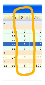
Sensori e Attuatori comunicano con i connettori di Input-Output chiamati “PIN”
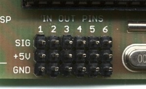
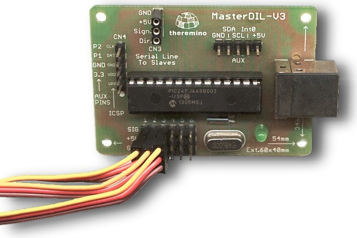
I Sensori e gli Attuatori comunicano con i PIN standard tramite 3 soli fili conduttori. Il primo conduttore (GND) è la massa, il secondo conduttore (+5V) è l’alimentazione, il terzo conduttore (SIG) è il segnale. I pin sono tutti uguali e sono tutti configurabili sia come IN che come OUT.
I moduli Master hanno sei PIN di InOut gli SlaveServo ne hanno dieci e i moduli CapSensor nessuno.
Sopra ai sei Pin c’è la scritta “IN OUT PINS”. Non fatevi confondere da questa scritta. I sei Pin sono tutti uguali e sono tutti configurabili, sia come IN, che come OUT.
Quando si effettuano i collegamenti può essere difficile leggere le scritte, per cui è bene sapere che: in tutti i componenti del sistema Theremino, il collegamento GND è sempre vicino al bordo della piastra.
I PIN configurati come OUT producono un tensione da 0 to 3,3 volt, quelli configurati come IN accettano tensioni da 0 to 3.3 Volt. Se si applicano ai PIN di input tensioni al di fuori da questo range le si devono limitare in corrente a 100 uA massimi (con un resistore da almeno 33k vicino al PIN) altrimenti la comunicazione USB viene disturbata e può anche interrompersi.
In caso di collegamenti lunghi, leggere anche This page.
Ecco un esempio di collegamento
Connettere interruttori e pulsanti con o senza PullUp
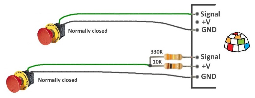
Qui si vedono due modi di connettere interruttori, microswitch, reed e pulsanti. Il primo modo è semplice ma il secondo è più tollerante ai disturbi.
Nella parte superiore si vede un collegamento diretto (impostare il Pin di input con PullUp)
Nella parte inferiore si vede un collegamento attraverso resistori di protezione (impostare il Pin di input senza PullUp). La presenza di un resistore di valore molto alto, in serie al filo “Signal”, limita la corrente, anche in caso di extra-tensioni molto alte (anche centinaia di Volt). Questo assicura che la comunicazione USB non verrà disturbata, anche in presenza di forti disturbi, indotti sui lunghi fili, da alimentatori esterni, motori o relè di potenza.
Se invece di collegare pulsanti, si facessero misure di tensione (quindi con il Pin di Input configurato come ADC) un resistore da 330K provocherebbe troppa caduta di tensione, e si dovrebbe ridurlo a 33K. Inoltre in questo caso il resistore da 10K non servirebbe e andrebbe eliminato.
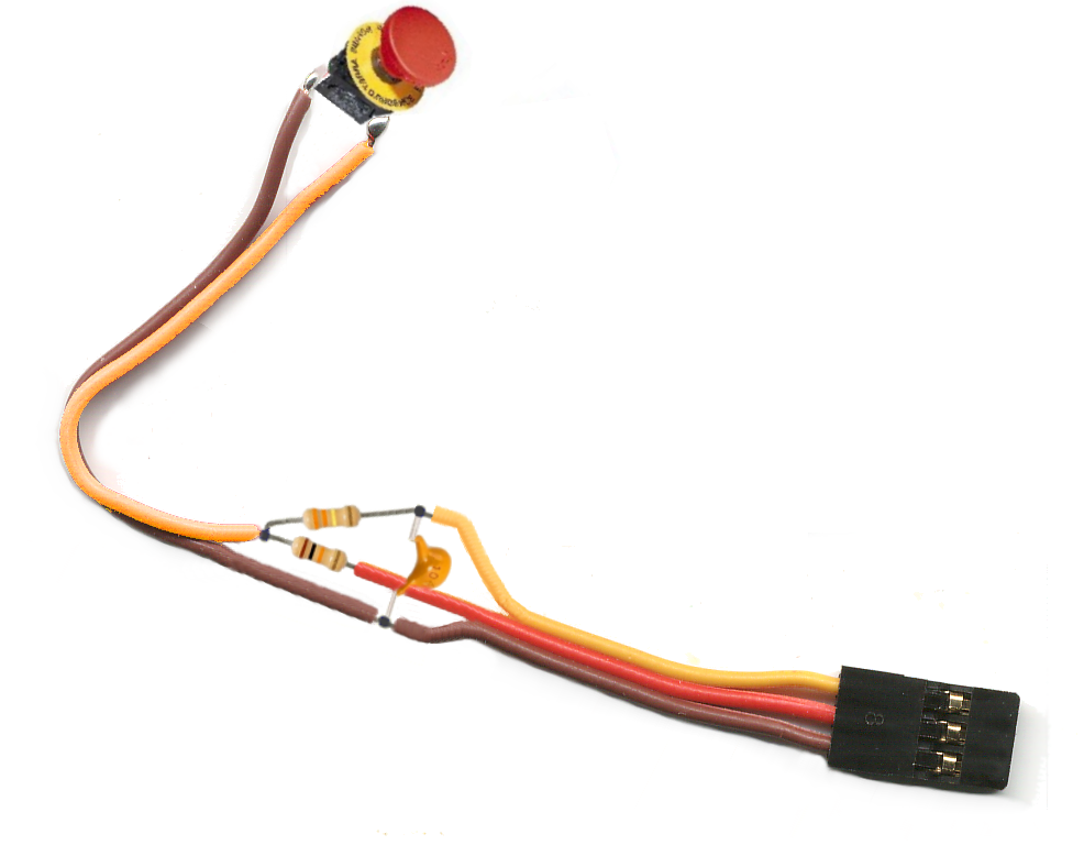
Connettere pulsanti in caso di forti disturbi elettrici
La soluzione mostrata nella sezione precedente protegge la comunicazione del Master con il PC, ma non impedisce che brevi disturbi impulsivi vengano interpretati per errore, come una chiusura manuale del pulsante.
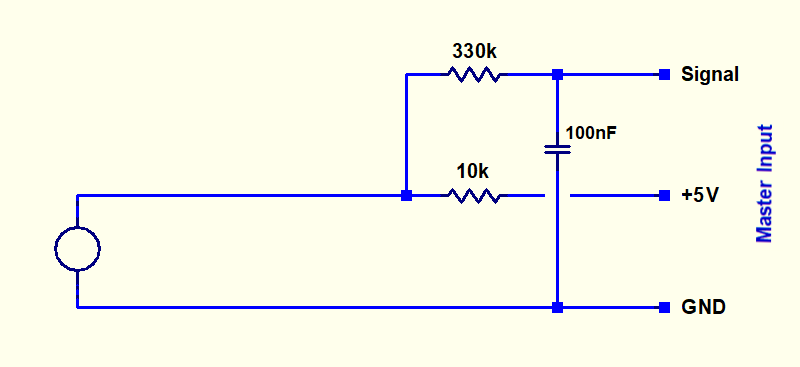
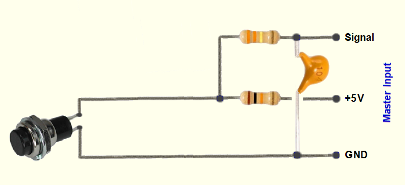
Per cui in ambienti difficili, ad esempio nel caso che i fili dei pulsanti passino accanto ai fili di alimentazione di un solenoide o di un motore, è consigliabile aggiungere anche un condensatore. Questo condensatore elimina gli impulsi più brevi di un decimo di secondo e aumenta ulteriormente la protezione in caso di extra-tensioni molto alte.
Le due immagini seguenti mostrano lo schema elettrico e pratico di questi collegamenti (fate click sulle immagini per ingrandirle).
La prossima immagine mostra come effettuare i collegamenti direttamente sui fili (fare click sulla immagine per ingrandirla).
Utilizzando un cavo con connettore femmina, si possono saldare i componenti direttamente sui fili.
Poi si potrebbero ricoprire i componenti con un pezzo di guaina termo-restringente.
In alternativa si potrebbe usare un piccolo quadrato di basetta millefori.
Ricordiamo che quando si utilizzano questi collegamenti (con resistore di protezione), si devono impostare il Pin di input senza PullUp.
Ricordiamo anche che, se invece di collegare pulsanti si facessero misure di tensione (quindi con il Pin di Input configurato come ADC), un resistore da 330K provocherebbe troppa caduta di tensione, e si dovrebbe ridurlo a 33K. Inoltre in questo caso il resistore da 10K non servirebbe e andrebbe eliminato. Inoltre la aggiunta del condensatore limita la banda passante dell’ADC a circa 10 Hz.
Connessioni ai Pin del Master e degli Slaves
Prendiamo come esempio di dover connettere un cavo schermato, per portare i segnali di tre Pin e il cinque Volt a grande distanza.
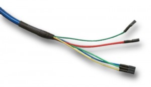
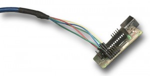
Si potrebbe intestare il cavo schermato con connettori singoli come si vede qui (cliccare sulle immagini per ingrandirle). I fili Blu, Verde chiaro e Giallo sono i tre segnali, il filo Rosso è il cinque Volt e il filo Verde scuro è la massa.
Ma è una soluzione difficile da costruire e poco affidabile. Queste foto si riferiscono a un accelerometro, che è stato spostato sovente da un banco all’altro del laboratorio. Dopo pochi mesi due dei cinque fili si sono rotti, sopra ai connettori che vanno al Master.
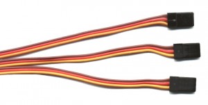
Molto meglio sacrificare tre prolunghe standard:
Le prolunghe tagliate a metà forniscono connettori femmina di buona qualità, con i fili ben collegati e molto robusti. Per una frazione del prezzo dei soli connettori si possono comprare sacchetti da dieci prolunghe standard da Hobby King.
Le prolunghe si collegano facilmente ai fili del cavo schermato. Si coprono le connessioni con guaina termo-restringente e si ottiene un cablaggio robusto e professionale.
Ecco un collegamento fatto bene.
I tre fili rossi portano il cinque volt e si collegano, tutti insieme, sul filo rosso del cavo schermato. I fili marrone sono la massa e si collegano, tutti e tre, alla calza del cavo schermato. I tre fili gialli sono i segnali di InOut dei Pin 1, 2 e 3 e li si collegano a tre dei fili interni del cavo schermato.
Dal lato opposto del cavo schermato si fa lo stesso, con le femmine ricavate dalla seconda metà dei cavi.
In caso di collegamenti lunghi, leggere anche This page.
I moduli Slaves e il modulo Master comunicano via seriale
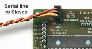
La linea seriale fornita dal Theremino Master non è una normale RS232 o RS485. Ma una linea speciale che trasmette e riceve su un singolo filo di segnale, secondo il protocollo DPM sviluppato da noi. I suoi vantaggi sono la alta velocità di comunicazione e l’autoriconoscimento dei moduli collegati. Maggiori informazioni qui: technical/protocol
Molti moduli Slave possono essere collegati alla linea seriale del Master.
Così come per i sensori, anche per i collegamenti della linea seriale, si usano le normali prolunghe per servo-comandi, reperibili a un ottimo prezzo presso www.hobbyking.com
Marrone = Massa
Rosso = +5V
Giallo = Segnale
Per collegamenti molto lunghi o particolari esigenze di alimentazione è possibile effettuare la comunicazione seriale su due fili (Massa e Segnale), eventualmente su cavo schermato. Ulteriori informazioni nella sezione Collegamenti lunghi e immunità ai disturbi
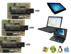
Master e Computer comunicano via USB
Anche più master possono essere connessi contemporaneamente allo stesso PC attraverso linee USB separate e verranno tutti riconosciuti dalla stessa applicazione HAL.
Usare più linee USB e più Master permette in alcuni casi di aumentare la velocità di comunicazione. In altri casi può servire per specializzare alcni Master per le comunicazioni lente e altri per comunicare con i canali che richiedono la massima frequenza di aggiornamento.
I cavi USB non devono essere speciali, di buona qualità o particolarmente corti. Abbiamo provato anche cavi molto lunghi (10 metri) e collegamenti con più cavi in serie (prolunghe) e tutti hanno funzionato perfettamente. Il sistema Theremino usa il protocollo USB 2.0, ma è stato possibile effettuare collegamenti senza errori, attraverso i normali HUB, anche di tipo USB 1.0.
Il programma HAL tiene in comunicazione i moduli Hardware con gli Slot
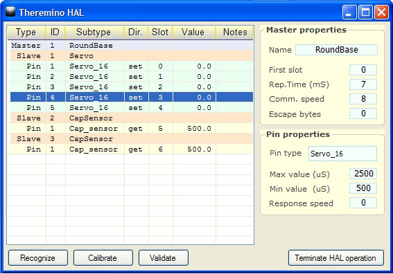
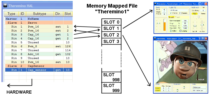
L’HAL ( Hardware Abstraction Layer ) semplifica la comunicazione USB e le complessità dell’hardware trasformando tutti i segnali in numeri “Float” che vengono scritti nelle caselle di ingresso uscita da 0 to 999 nominate “Slot”, o letti dalle stesse e inviati verso l’hardware.
.
Gli SLOT
Gli “Slot” del sistema Theremino sono identificati con un numero da 0 to 999 e fanno tutti parte del MemoryMappedFile con nome “Theremino1”.
Ogni slot contiene un numero “Float” che può essere letto o scritto da qualunque componente del sistema Theremino.
In questa immagine soltanto l’HAL scrive negli slot ma in realtà tutti i componenti del sistema possono sia leggere che scrivere in uno qualunque degli slot, anche se già usato da altri.
I 1000 slot disponibili sono usabili liberamente esiste una sola regola:
Molte applicazioni e molti PIN possono leggere lo stesso slot, ma si deve evitare di scrivere in molti sul medesimo slot, facendolo non si rompe nulla ma si ottengono risultati indefiniti.
Se si inviano più flussi di dati verso lo stesso slot allora i dati si mischiano e vince l’ultimo a scrivere, se si vogliono unire i dati in modo ordinato sono necessarie delle regole.
Per stabilire regole matematiche e logiche tra gli Slot, ed anche per scrivere algoritmi di comportamento complessi, si usa “Theremino_Script” oppure qualunque linguaggio di programmazione come C++, CSharp, VbNet, VB6, Python o Pascal, ma è anche possibile usare linguaggi visuali come MaxMSP, Processing, PureData, LabView e EyesWeb.
Per MaxMSP sono disponibili i Plugin e gli esempi qui: downloads/foundations
Gli SLOT per le stringhe di testo
Gli SlotText sono simili agli Slot normali, hanno indirizzi simili (da 0 to 999) e si usano in modo simile ad essi ma a differenza degli Slot, che contengono numeri (interi o a virgola mobile), gli SlotText contengono stringhe di caratteri.
I caratteri utilizzati internamente sono di tipo unicode per permettere di scrivere in diverse lingue (ad esempio il cinese) e utilizzano due byte per ogni carattere.
Ogni SlotText può contenere stringhe di testo lunghe fino a 100 mila caratteri. Se si superano i 100 mila caratteri al posto del testo viene scritto un breve messaggio di errore.
Gli SlotText non utilizzano il MemoryMappedFile “Theremino1”, ma usano un MemoryMappedFiles diverso per ogni SlotText. I nomi di questi file vanno da “ThereminoSS0” to “ThereminoSS999” (dove ThereminoSS sta per Theremino String Slots).
E infine gli SlotText sono utilizzabili solo per comunicare tra applicazioni e non per comunicare con gli HAL e i moduli Master o Arduino.
Attualmente (giugno 2022) le uniche applicazioni che utilizzano gli SlotText sono:
– QRdecoder, che li usa per il testo decodificato dai QR-Code e BAR-code.
– Automation (dalla versione 7 in poi), che fornisce i comandi SlotText per scrivere e leggere gli SlotText.
– SlotViewer, che nelle versioni più recenti può utilizzare sia gli Slot numerici che quelli di testo.
– Cobot, che può ricevere comandi dall’esterno e anche inviare comandi asincroni ad Automation per mezzo dell’evento “Commands From Cobot”.
Per utilizzare le comunicazioni tra Automation e la applicazione COBOT leggete le pagine seguenti nel file di istruzioni di Automation:
- SlotText
- Event_CommandsFromCobot
- I comandi da COBOT a Automation
- I comandi da Automation a COBOT
Nella cartella “Sources” di Automation (sempre dalla versione 7 in poi che pubblicheremo entro la fine del 2021) troverete il nuovo file “Class_ThereminoStrings.vb” che i programmatori possono utilizzare per aggiungere gli SlotText anche alle loro applicazioni.
I Memory Mapped Files
Gli SLOT sono basati sui “Memory Mapped Files” che sono poco conosciuti ma utilissimi.
Comunicare tramite i “Memory Mapped Files” è estremamente efficiente, in poche decine di microsecondi si possono trasferire centinaia di numeri “Float” tra programmi separati, con thread differenti e scritti in linguaggi diversi.
Il “Memory Mapped File” chiamato “Theremino1” è lungo 4096 byte e contiene i 1000 slot usati dal sistema Theremino. Tutti i programmi del sistema Theremino possono scrivere e leggere i loro dati, sotto forma di numeri float, nei 1000 slot di questo file.
Ogni slot è lungo quattro byte per cui quando si usano funzioni di memorizzazione a basso livello si deve moltiplicare lo “Slot” per quattro per ottenere l’indice al byte nel MemoryMappedFile.
Sono disponibili i programmi di prova ed esempio, con i sorgenti, nei principali linguaggi di programmazione. Usando questi esempi è molto facile dotare qualunque programma della possibilità di comunicare con il sistema Theremino.
Sono anche disponibili gli “External” per Max4 e Max5 che si trovano nel file “MaxInstall.zip”. In questo modo è possibile far comunicare le “Patch” di Max con il sistema “Theremino” attraverso i MemoryMappedFiles.
Collegamenti con cavetti standard
Per tutti i collegamenti tra pin, sensori e attuatori ed anche per la linea di comunicazione seriale sono molto comode le normali prolunghe per servo-comandi reperibili ad un ottimo prezzo presso “www.hobbyking.com” nella sezione “Hardware e accessories” / “Wires and plugs” / “Servo Wire & Servo Plugs”
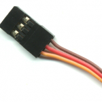
Cavetto standard con connettore maschio-femmina
Brown   = Gnd
Red     = +5V
Yellow  = Signal
- Per correnti fino a 0.5 Ampere usare i 26 AWG (0.13 mmq)
- Per correnti fino a 1 o 2 Ampere usare i 22 AWG (0.33 mmq)
Maggiori informazioni sui cavi di collegamento per alte correnti e linee molto lunghe, nonché prezzi indicativi e links nella sezione: connection-cables
I numeri Float
(valori minimi e massimi validi per gli Slot numerici)
I numeri “Float” sono numeri in virgola mobile da 32 bit (singola precisione). Il sistema Theremino usa sempre i “Float” invece dei numeri “Interi” o “Double” per i seguenti motivi:
1) Essendo lunghi 32 bit vengono scritti e letti in una sola istruzione del processore e non necessitano quindi di meccanismi di sincronizzazione per evitare errori.
2) Pur essendo numeri con la virgola possono contenere senza errori o arrotondamenti qualunque numero intero da -16`000`000 a +16`000`000 e rotti, e quindi contenere facilmente i valori da 0 to 65535 (16 bit) e anche fino ai 24 bit dei migliori sensori e attuatori esistenti.
3) Possono essere usati per inviare 16 milioni di differenti comunicazioni “di servizio” per mezzo dei valori NaN (not a number) e NaNs ( NaN di segnalazione ).
4) Possono anche contenere i valori speciali “+infinity” e “-infinity”, utili quando i calcoli producono valori molto elevati.
5) La precisione dei “Float” è da migliaia a milioni di volte superiore rispetto alla precisione richiesta, perché sono usati solo per comunicare e non per eseguire calcoli.
6) Tutti i processori attuali trasferiscono 32 bit in una sola istruzione, per cui l’efficienza è massima e due programmi separati possono comunicare in pochi microsecondi.
Per maggiori particolari sui numeri “Float” leggere le pagine seguenti.
– – – – – –
Float – Single precision, 32 bit, floating point numbers
Positive max: 3.4028235 E+38
Positive min: 1.401298 E-45
Negative max: -3.4028235 E+38
Negative min: -1.401298 E-45
Max integer stored without rounding errors : +16’777’216
Min integer stored without rounding errors : -16’777’216
Max integer visualized (7 digits rounded): +9’999’999
Min integer visualized (7 digits rounded): -9’999’999
+Zero: 0 00000000 00000000000000000000000 (0000 0000)
-Zero: 1 00000000 00000000000000000000000 (8000 0000)
+Infinity: 0 11111111 00000000000000000000000 (7F80 0000)
-Infinity: 1 11111111 00000000000000000000000 (FF80 0000)
Positive NANS
from: 0 11111111 00000000000000000000001 (7F80 0001)
to: 0 11111111 01111111111111111111111 (7FBF FFFF) (4’194’303 values)
Negative NANS
from: 1 11111111 00000000000000000000001 (FF80 0001)
to: 1 11111111 01111111111111111111111 (FFBF FFFF) (4’194’303 values)
Positive NAN
from: 0 11111111 10000000000000000000000 (7FC0 0000)
to: 0 11111111 11111111111111111111111 (7FFF FFFF ) (4’194’304 values)
Negative NAN
from: 1 11111111 10000000000000000000000 (FFC0 0000)
to: 1 11111111 11111111111111111111111 ( FFFF FFFF ) (4’194’304 values)
– – – – – –
Special Values
IEEE reserves exponent field values of all 0s and all 1s to denote special values in the floating-point scheme.
Zero – As mentioned above, zero is not directly representable in the straight format, due to the assumption of a leading 1 (we need to specify a true zero mantissa to yield a value of zero). Zero is a special value denoted with an exponent field of zero and a fraction field of zero. Note that -0 and +0 are distinct values, though they both compare as equal.
Denormalized – If the exponent is all 0s, but the fraction is non-zero (else it would be interpreted as zero), then the value is a denormalized number, which does not have an assumed leading 1 before the binary point. Thus, this represents a number (-1)s × 0.f × 2-126, where s is the sign bit and f is the fraction. For double precision, denormalized numbers are of the form (-1)s × 0.f × 2-1022. From this you can interpret zero as a special type of denormalized number.
Infinity – The values +infinity and -infinity are denoted with an exponent of all 1s and a fraction of all 0s. The sign bit distinguishes between negative infinity and positive infinity. Being able to denote infinity as a specific value is useful because it allows operations to continue past overflow situations. Operations with infinite values are defined in IEEE floating point.
Not A Number – The value NaN (Not a Number) is used to represent a value that does not represent a real number. NaN’s are represented by a bit pattern with an exponent of all 1s and a non-zero fraction. There are two categories of NaN: QNaN (Quiet NaN) and SNaN (Signalling NaN).
QNaN – A QNaN is a NaN with the most significant fraction bit set. QNaN’s propagate freely through most arithmetic operations. These values pop out of an operation when the result is not mathematically defined.
SNaN – An SNaN is a NaN with the most significant fraction bit clear. It is used to signal an exception when used in operations. SNaN’s can be handy to assign to uninitialized variables to trap premature usage.
Semantically, QNaN’s denote indeterminate operations, while SNaN’s denote invalid operations.
– – – – – –
Special Operations
Operations on special numbers are well-defined by IEEE. In the simplest case, any operation with a NaN yields a NaN result. Other operations are as follows:
| Operation | Result |
| n ÷ ±Infinity | 0 |
| ±Infinity × ±Infinity | ±Infinity |
| ±nonzero ÷ 0 | ±Infinity |
| Infinity + Infinity | Infinity |
| ±0 ÷ ±0 | NaN |
| Infinity – Infinity | NaN |
| ±Infinity ÷ ±Infinity | NaN |
| ±Infinity × 0 | NaN |
– – – – – –
Summary
| Sign | Exponent (e) | Fraction (f) | Value |
| 0 | 00..00 | 00..00 | +0 |
| 0 | 00..00 | 00..01 : 11..11 |
Positive Denormalized Real 0.f × 2(-b+1) |
| 0 | 00..01 : 11..10 |
XX..XX | Positive Normalized Real 1.f × 2(e–b) |
| 0 | 11..11 | 00..00 | +Infinity |
| 0 | 11..11 | 00..01 : 01..11 |
SNaN |
| 0 | 11..11 | 10..00 : 11..11 |
QNaN |
| 1 | 00..00 | 00..00 | -0 |
| 1 | 00..00 | 00..01 : 11..11 |
Negative Denormalized Real -0.f × 2(-b+1) |
| 1 | 00..01 : 11..10 |
XX..XX | Negative Normalized Real -1.f × 2(e–b) |
| 1 | 11..11 | 00..00 | -Infinity |
| 1 | 11..11 | 00..01 : 01..11 |
SNaN |
| 1 | 11..11 | 10..00 : 11.11 |
QNaN |

