
Piezoelectric sensors
Piezoelectric sensors are easily available on eBay and cheap (about 30 cents per piece). Sellers offer them in diameters from 20, 27 and 35 mm, in packs of 5 or ten pieces: http://www.ebay.it/itm/360494605075

With piezoelectric sensors can achieve effects similar to Mogees, but with more flexibility. Mogees bears a single sensor, instead with Theremino sensors can be connected are unlimited. And finally, In addition to percussion, with the application also tuned notes and chords can be played Theremin. You can get very interesting effects.
Piezo sensors can function as generic buttons, for applications of Automation and for music and videos. But especially with the Theremin, or through the SlotsToMidi, to any hardware synthesizer or VST. And even better with the drum and percussion synthesizers.
The following videos demonstrate the modular system Theremino. The signals of piezoelectric sensors is collected from four inputs of a form Theremino_Master. The inputs are configured as Adc16. and the four numeric values, sent to four slots (area of communication between applications). Finally we use the Theremino_SlotsToMidi application, to send MIDI signals to a VST freeware. The VST used is the SuperDrmFX, a sampler of drums very realistic.
The material for putting this all together, costs less than 25 Euro (Remember though that the system Theremino is only educational and does not sell hardware or software).
Videos with piezo sensors that drive the application Theremin

Theremino_PiezoSensors_Video In this video two piezoelectric discs are glued below a skin for TOM from 20 cm. The signals through the slots are sent to the synthesizer Theremin. One of the two signals were used for the volume, but you can get the same effect, even with a single sensor.
Videos with piezo sensors and a percussion synthesizer

Theremino_PiezoDrums_Video_1
Theremino_PiezoDrums_Video_2
Theremino_PiezoDrums_Video_3
Theremino_PiezoDrums_Video_4_Increased_Dynamics
The videos have not been retouched. The sounds come directly from the VST synthesizer, with no further processing. What you hear is exactly what you get, drumming fingers, on piezoelectric sensors.
Unfortunately, compressing the video slowed the frames. The fast drumming of the fingers is completely gone, but can you imagine listening to the sounds.
The fourth video shows the improvement of dynamics that we got with the version 1.3 of SlotsToMidi. Now you can swipe the snare skin, from a subheading that almost doesn't feel, up to rise gradually to absurd volumes. Heard in compressed video does not make it like the real thing. We connected the large speakers sound card (3 vie woofer 35 cm) and the sound is “monstrous”.
Adapters for piezoelectric sensors
The adapters that we propose are simple to build and work better than the many schemes that are on the internet.
Attention: The operating principle of our sensors is not the same as those of commercial batteries. The signals are not interchangeable. For maximum performance, our sensors do not transmit an audio signal, but a value proportional to the pressure. This allowed us to obtain a sound control and a dynamic, higher than those of commercial electronic batteries, with the classic Pad not supplied.
If you want the best results, the mechanics of the pads must be built with special techniques. The pads of commercial batteries can also work with our sensors. But not funzionaranno very well. Are generally too stiff (seems to beat on a piece of wood) and then generate mainly high frequency vibrations (Come on 50 to 200 Hz up) Instead we are interested in measuring the force with which you strike. And these forces have very low frequencies (from 2 to 20 Hz).
The advantages of these adapters are:
- Increased sensitivity. Then you get a good signal on every surface.
- Reference level very close to zero, and then more dynamic.
- With roughly logarithmic response curve. Why you get better Dynamics, throughout the range of the “pianissimo” and the “FORTISSIMO”.
- Total elimination of the danger of overloading the inputs. Then the Master module not loses communication, even if an elephant jumps onto the floppy.
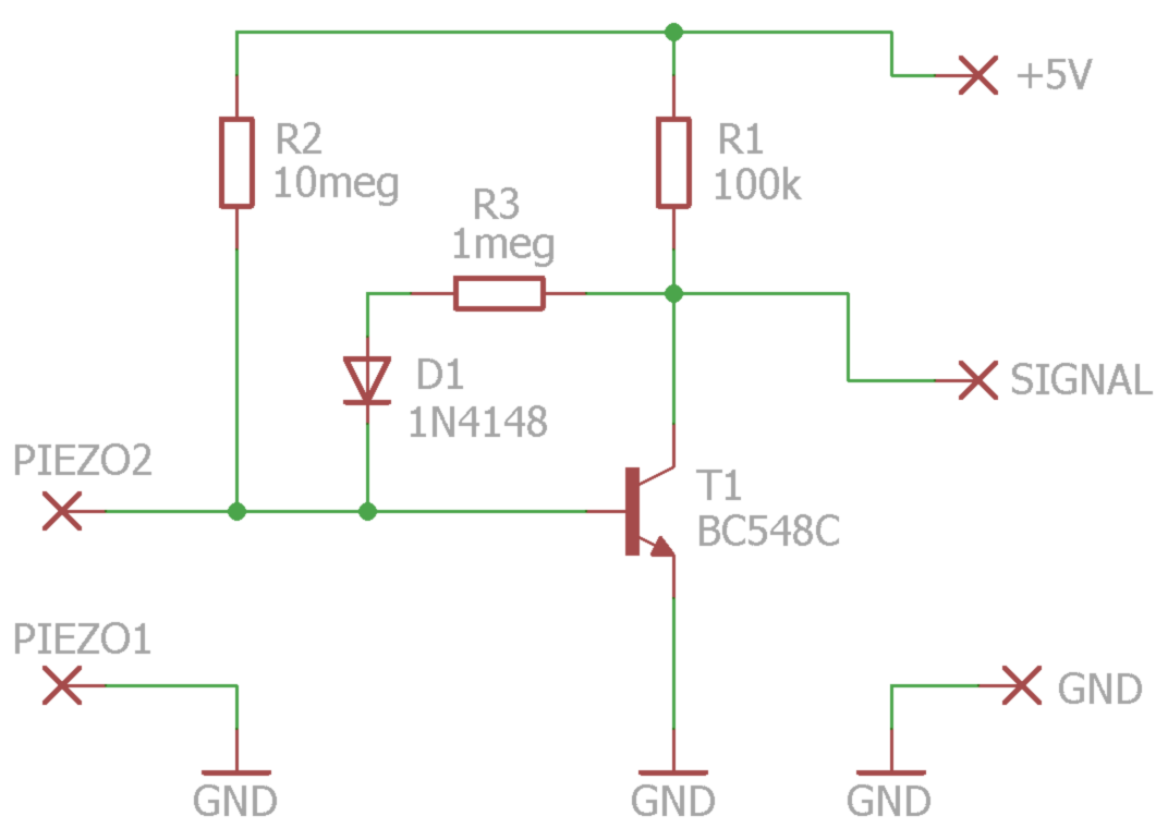
- The circuit can also be operated with only three components T1, R1 and R2. Adding R3 and D1, you get a better resistance to saturation and a shorter recovery time (It increases the precision for percussion and you can play faster).
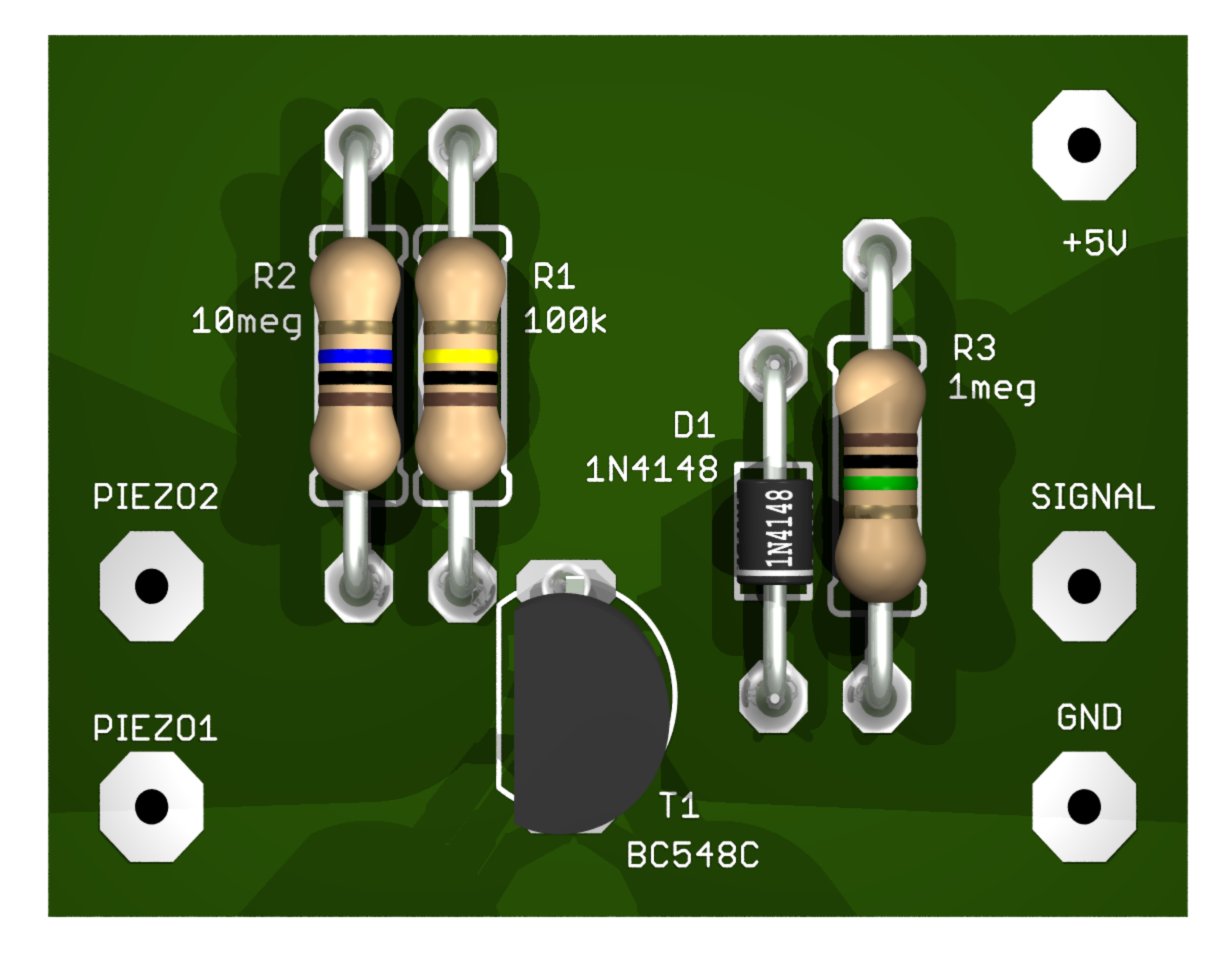
PCB and circuit diagram (SMD version)


Eagle PCB project downloads, images, Gcode for the cutter and simulation LTSpice:
https://www.theremino.com/wp-content/uploads/files/Adapter_Piezo.zip
PCB and circuit diagram (version with holes)
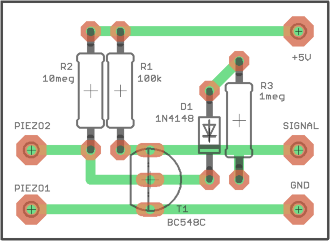
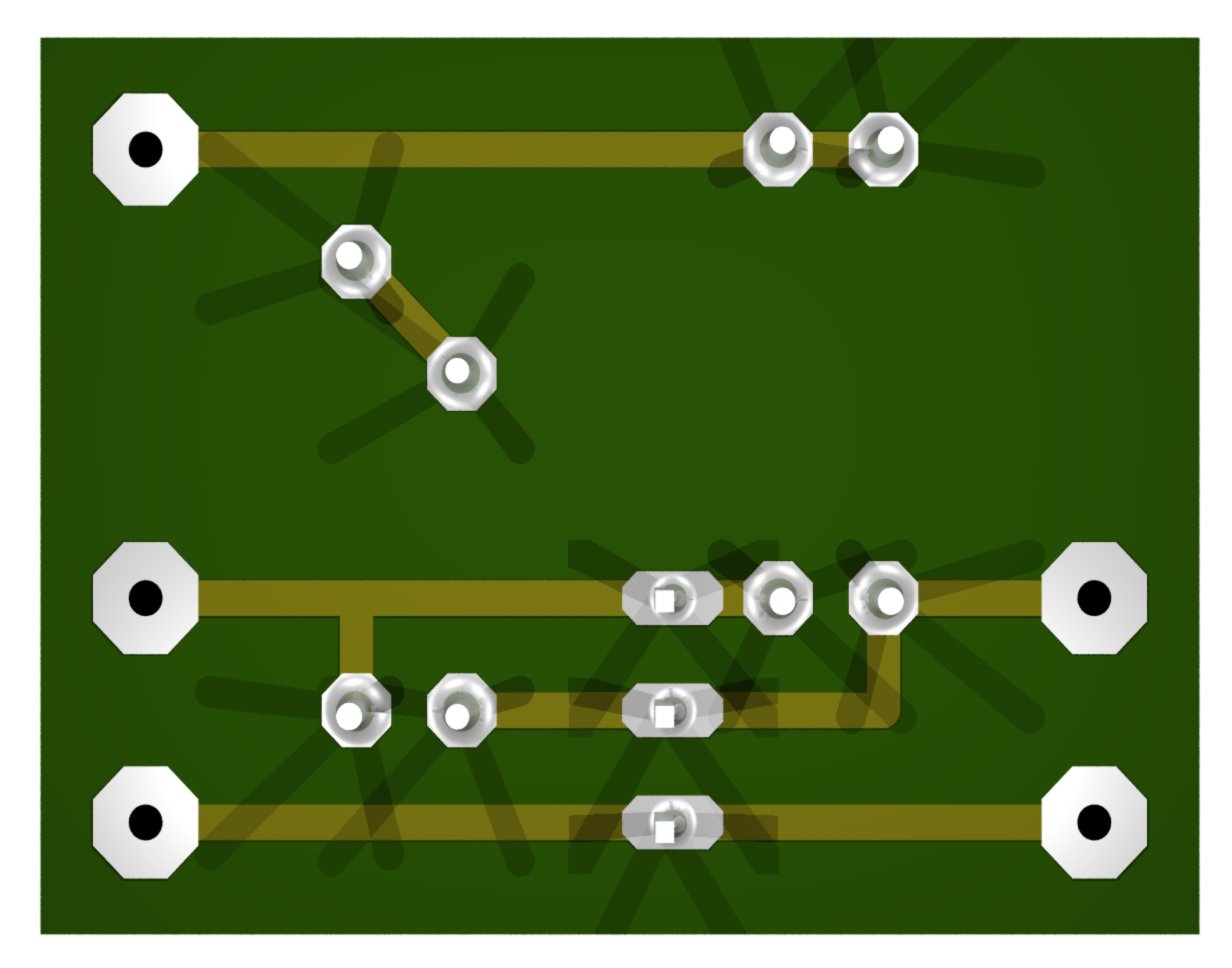
You can build this version of a piece of thousand-holes breadboard. You may want to count the holes to insert the components in the right holes. Then they use the same wires of the components to make the connections on the rear side. They bend the wires at right angles and cut them to the correct length. Finally enough about ten drops of solder in the right places.
Eagle PCB project downloads, images, Gcode for the cutter and simulation LTSpice:
HTTPS://www.theremino.com/wp-content/uploads/files/Adapter_PiezoThruHole.zip
for components Notes
Use BC547B, Bc547c, BC548B, BC548C, Bc846b, BC846C or similar transistors. Must be an NPN transistor, and must end with “B” or better with “C” (the letter “B” indicates a current gain around 300..400, And the “C” around the 500).
If the transistor has a gain too low then the signal read by the application HAL gets up too. You control this value at rest (don't move the diskette). The BC547C usually give a signal around 25 (on 1000). Transistors with “B” final damage about 30. If you measure more than 40..50 then it is good to find higher gain transistors.
Some disks have the positive Pole on the outside, others within. When you press, the signal on HAL should rise, failure to do so should invert, Red and brown wires that go to the disk. For percussion it is important that the signal is the right way, otherwise the sound arrives late and it's hard to go to time. Check the phase as explained in this chapter.
Reduce the sensitivity of the sensors
This adapters are very sensitive. In some cases you may need to decrease the sensitivity. It would be difficult to increase it, but there are many ways to reduce it.
- Mitigate mechanically vibrations, soft materials.
- Interpose a layer of foam, between the vibrating surface and the sensors. This protects also the sensors.
- Reduce the sensitivity of the circuit electrically replacing R2 with a gradually lower resistor. Values to use are 10 Mega (maximum sensitivity), 4.7 Mega, 2.2 Mega, 1 Mega and 470 K (minimum sensitivity). You should not go below to 470 K, otherwise the tension could no longer reach the maximum value, and we would lose part of the dynamics.
Mechanical methods to attenuate vibrations and the reduction of R2 can also be used together, for extreme cases (for example, for whom out of wooden boxes, with gorilla plays drums and exaggerated volumes on stage).
As a general principle it must mitigate quite, to make the battery insensitive to vibration, caused by low and the crate itself (Kick drum). Are the same problems that occur, amplifying microphones normal batteries. The engineers are used to solve them with duct tape and rags.
Wiring with welded components in the air


This is the easiest method. If done well is fast and robust. Click on images to enlarge them.
Wiring with copper adhesive tape


Copper adhesive tape cut with scissors and paste it onto a piece of plastic. It takes some skill to do a good job, read the advice here: /technical/tables-and-notes # coppertape
Since the base is plastic you have to warm up a little. When the pitches are hot glue loses traction. Then you have to solder to points and carefully so as not to move. But when cooling are very robust. Pull tear before the threads of touring.
Apply the discs to the vibrating surface
We initially thought that the disks worked for compression so we tried several methods of application in different sizes and weights. Then we discovered that the disks work for twist, so the weights don't serve.
Simply apply the discs with double sided tape (thick type). Beware that once applied will not be able to move or remove. Pulling bend and break.
 Click on images to enlarge them!
Here you see a puck glued to the underside of a skin by Tom. A second disk already has double-sided tape and is ready to be applied to the skin.
There are many variables, supporting material, the force with which you strike, playing with chopsticks or fingers, any foam to dampen vibration, the point at which the disks. What you should get is to play piano and forte in a pleasant way, as shown in the next pictures.


- The left picture shows the signal you get crawling on the skin or drumming fingers lightly.
- The image on the right was obtained drumming with growing force. Note that while beating strong, dynamic remains for the “FORTISSIMO”.
Put being piezoelectric sensors


This Pad is just one example. Each can do the sensors as you wish, Maybe round or glued under the skin of a Tom. But this example is important to explain a concept. Note that the foam has two sides with two strips of double-sided tape and that the Center was emptied with scissors. Like this, by pressing in the Middle, the diskette embarks, with the bottom center, and sides upwards.
The disks work for twist, not for pressure and it is important that, When you press, the twist is in the right direction. The right signal causes a signal negative on the base of the transistor and then a signal positive in the scope of HAL.

You can't trust the fact that the Centre is always positive, or failure, We found discs that give the signal to the contrary.
To verify that the disk is in the right direction, you open the oscilloscope HAL program, by double clicking on the line right. Then you press slowly into the Center for half a second and then you release of stroke. If the signal on the oscilloscope leaps upward when you release the pressure, then the disk is connected in reverse. Be careful not to take too floppy disks, If you overdo it feels they do “Crick” and then work a little’ worse.


The delay between the percussion and sound (“t” in images) must be at least, otherwise it becomes difficult to play in time. The signal instead causes a very big lag (the image on the right). And, even worse, with the signal on the contrary, the delay time lengthens and shortens depending on the strength with which you strike. It then becomes impossible to perform with a precise rhythm.
If the signal is on the contrary you can remove the disk and insert it upside down. Or you can reverse the two wires that go to the adapter. Better to reverse the wires from the adapter, because the disks are delicate and it is better not to solder several times.
Regulations for piezo sensors
HAL application settings

Set “Comm. speed” at least in 9, so you have a fairly high repetition rate. A repetition frequency of 300 FPS is sufficient and causes a delay of only 3 mS (musicians call it “latency”). This speed control may save CPU on slow machines like the Raspberry. Instead on fast machines you can avoid thinking about it and always set the speed 12.
Individual adjustment PIN
First you set the pins of piezo sensors as Adc16 (or Adc8 for a lower resolution). Then you adjust the following parameters:
- Response speed – Determines the speed of response and has a big effect on the signal. When you set the pins is set to the value “30”, that is suitable for a moderately fast response. Melodic applications, You can use low values, even up to 1. But for percussion you normally use values from 90 to 100.
- MaxValue – Normally use default value “1000”.
- MinValue – Determines the sensitivity of the individual sensor. The global adjustment of the sensitivity is the box “Trigger notes value”, the SlotsToMidi application. But individual adjustments are the MinValue, for each Pin. Raising MinValue (around 30), the sensor begins to give eating disorders, even if you don't play. Instead of lowering it below zero, the sensor becomes progressively more deaf. To have the snare very sensitive is good to raise MinValue, until you hear the snare drum playing alone, and then lower it a bit.


These are three examples of adjusting parameters of HAL. The first relates to the “Crate” (Kick Drum), the second to “Snare drum” (Snare Drum) and the third to a “Drum” (Tom).
Note that the snare drum was made more sensitive (Min value = 15), in order to make it sound even touching it. Instead the Tom has been desensitized (Min value = -50), to make no sounds, When you hit the adjacent pads.
The numbers written in slots, determine the instrument being played. It starts from 200, because in SlotToMidi we set 200 as the first slot. Usually the first MIDI instrument battery is the case, then you jump two and located the snare, And so on…
– – – – – – –
SlotsToMidi application settings

To send the piezo-electric sensor signals to SuperDrumFX (or other drum synths), using the following adjustments:
- First slot – Normally you set in 200 and must match the first slot, that you set in the HAL.
- Consecutive slots – The number of slots to read and transfer to the MIDI. Normally for percussion 20 or 30 Slots are sufficient.
- Trigger notes value – You raise this value until all the pads are silent. It rises further to make them less sensitive. Normal values for percussion range from 50 to 100.
- Velocity multiplier – Normally you set in “1”. With this value, the normal range of the sensors of the system Theremino (from 0 to 1000), is transformed into MIDI velocity by 0 to 127. Sometimes you may want to decrease this value, to reduce the “expression” of the entire instrument. Or you can raise, If the sensors give little signal.
- Midi output device – Normally you set “Out To MIDI Yoke: 1” and this number must be the same that you set as “Midi input” by SuperDrumFX .
- MIDI channel – The MIDI output channel. Normally “10” for percussion.
- First midi notes – The first MIDI note that corresponds to the first Slot set. Normally 36 corresponds to the cashier (Kick Drum), 38 the snare (Snare Drum) And so on… See the following table.
- Compander – Signal compression and expansion. I normally use the value “1”. With lower numbers (up to 0.5) you get a rapprochement between the “floor” and the “strong”. Instead high-numbered (up to 2) you get a more dynamic. This works differently from that of SuperDrumFX Compander. On SuperDrumFX when you set up a strong expansion, the maximum volume can reach dangerous levels and there is a risk of damage to the audio system. Faint sounds are lowered and used instead in SlotsToMidi the maximum level remains constant. The regulation is therefore easier.
- Fast notes – Normally you set as “fast” only the notes “38 40 42”. These are the notes of the snare drum (Snare Drum) they must be able to run very fast vibration rolled and. All other percussion instruments and especially the case (Kick Drum) sound better with single shots and net, so no “fast” for them.
– – – – – – –
Slot table and MIDI notes for battery
This table assumes that you have set “First slot = 200″ and “First midi note = 36”. The tools and the notes are those of normal SuperDrumFX configuration. All batteries MIDI using this arrangement of notes, at least for the core tools.
| Slot (HAL) | Notes (MIDI) | Instrument ENG | Tool ENG |
| 200 | 36 | Kick | Crate |
| 201 | 37 | ||
| 202 | 38 | Snare / Carpet / Position | Snare drum / Tailpiece / Variations |
| 203 | 39 | ||
| 204 | 40 | Rim Shot / Cross Stick | Edge Nick / Crossed chopsticks |
| 205 | 41 | Floor Tom 2 | First Gable |
| 206 | 42 | HH Close | Closed hihat |
| 207 | 43 | Floor Tom 1 | According To Gable |
| 208 | 44 | HH Foot | The Hi-Hat pedal |
| 209 | 45 | Tom 2 | According To Tom |
| 210 | 46 | HH Open | Open hihat |
| 211 | 47 | ||
| 212 | 48 | Tom 1 | First Tom |
| 213 | 49 | Cymbal 1 | First course |
| 214 | 50 | ||
| 215 | 51 | Ride Bell | Plate “Ride” |
| 216 | 52 | Cymbal 2 | Main course |
| 217 | 53 | Ride Rim | Plate “Crash” |
| 218 | 54 | ||
| 219 | 55 | Cymbal 1 | First course |
| 220 | 56 | ||
| 221 | 57 | Cymbal 2 | Main course |
| 222 | 58 |