
Accelerometers with 3 axes
These components are great for the seismographs, by setting their bandwidth (from 0.5 Hz to 50 Hz) are great for detecting earthquakes from around -1 Richter scale in +7, but can also be used for other applications requiring a control similar to the "Wiimote" Nintendo console.
We recommend the LIS 344, that is less noisy than the other models and could get even one or two degrees Richter under zero.
Pre-assembled modules


A module with the Robot-ADXL335 can be bought in Italy for about 19 Euro:
http://www.robot-italy.com/it/lilypad-accelerometer-adxl335.html


The LIS344 had sensitivity adjustable, six times less noise, and it only costs 12 Euro, It is on eBay: http://www.ebay.com (try LIS344)
Or here: http://www.bravekit.com/sensor_modules/LIS244_accelerometer_analog_sensor_module
Data sheets in PDF format
ADXL335 DataSheet
MMA7361_DataSheet
LIS344_DataSheet
Comparison of features
| ____________ | ADXL335 | MMA7361 | LIS344ALH |
| Power supply | 1.8 to 3.6 V | 2.2 to 3.6 V | 2.4 to 3.6 V |
| Current | 320 UA | 400 UA | 680 UA |
| End of scale | 3G | 1.5G or 6G | 2G or 6G |
| Sensitivity | 330 mV/G | 800 mV/G | 660 mV/G |
| Noise | 300 uG/sqHz | 350 uG/sqHz | 50 uG/sqHz |
| Pass band max | 250 Hz | 3 KHz | 1.8 KHz |
| Price assembled | 19 Euro | 8 Euro | 12 Euro |
Notes to the ADXL335
The pin X, Y and Z must be connected to “Signal” three input pins configured as ADC. For normal operations the pin ST can be left open or connected to GND. With the capacitors from 100 NF mounted on this plate the passband is 50 Hz, replacing them with three capacitors from 47 NF bandwidth becomes 100 Hz.
Notes to the MMA7361
The pin X, Y and Z must be connected to “Signal” three input pins configured as ADC. The VDD (6) must be connected to the 3,3 Volts stabilized and the VSS (5) must be connected to GND. For normal operation the pin sleep (7) and the Gselect (10) must be connected with the VDD (6) For normal operation the pin SelfTest (13) must be connected with VSS (5) With the capacitors from 2.2 NF mounted on the plate the passband is 2500 Hz, adding three capacitors from 47 NF bandwidth becomes 100 Hz and noise decreases very much.

The supply voltage is stabilized at 3.3 Volt is available on all modules of the Theremino on pin 2 (VDD) the ICSP connector.
– – – – – –
Notes for LIS344
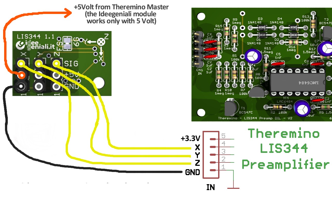
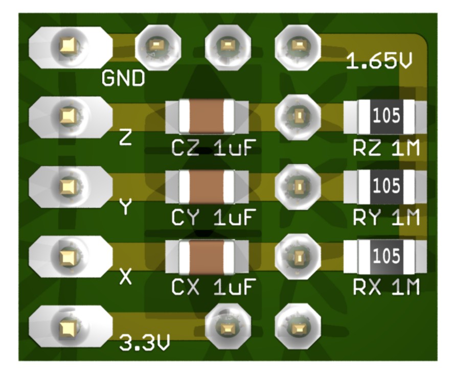
The pin X, Y and Z must be connected to “Signal” three input pins configured as ADC. Make the connections as shown in the following image.

Note 1 – Check that the drop of Tin is right (on the side marked with 3.3 Volts)
Note 2 – Connect the + 5 volt to VIN and leave the VDD opened (not connected)
With the capacitors from 1 NF mounted on the plate is 3 kHz bandwidth, adding three capacitors from 47 NF between signals and bulk bandwidth becomes 100 Hz and noise decreases very much.
With all models of accelerometer if the link is down (more than a few centimeters) It is recommended to use a shielded cable with four internal wires. As shown in this photo the wire GND should be connected to the analogue of the ADC, i.e. the pole mass Input pins and not, for example,, the ICSP connector or GND AUX.
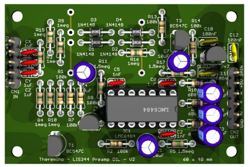
Preamp for accelerometers and Geophones
With this preamplifier accelerometers can become much more sensitive and Geophones can be used for earthquakes (not for the micro-earthquakes) no need to use the GeoPreamp.
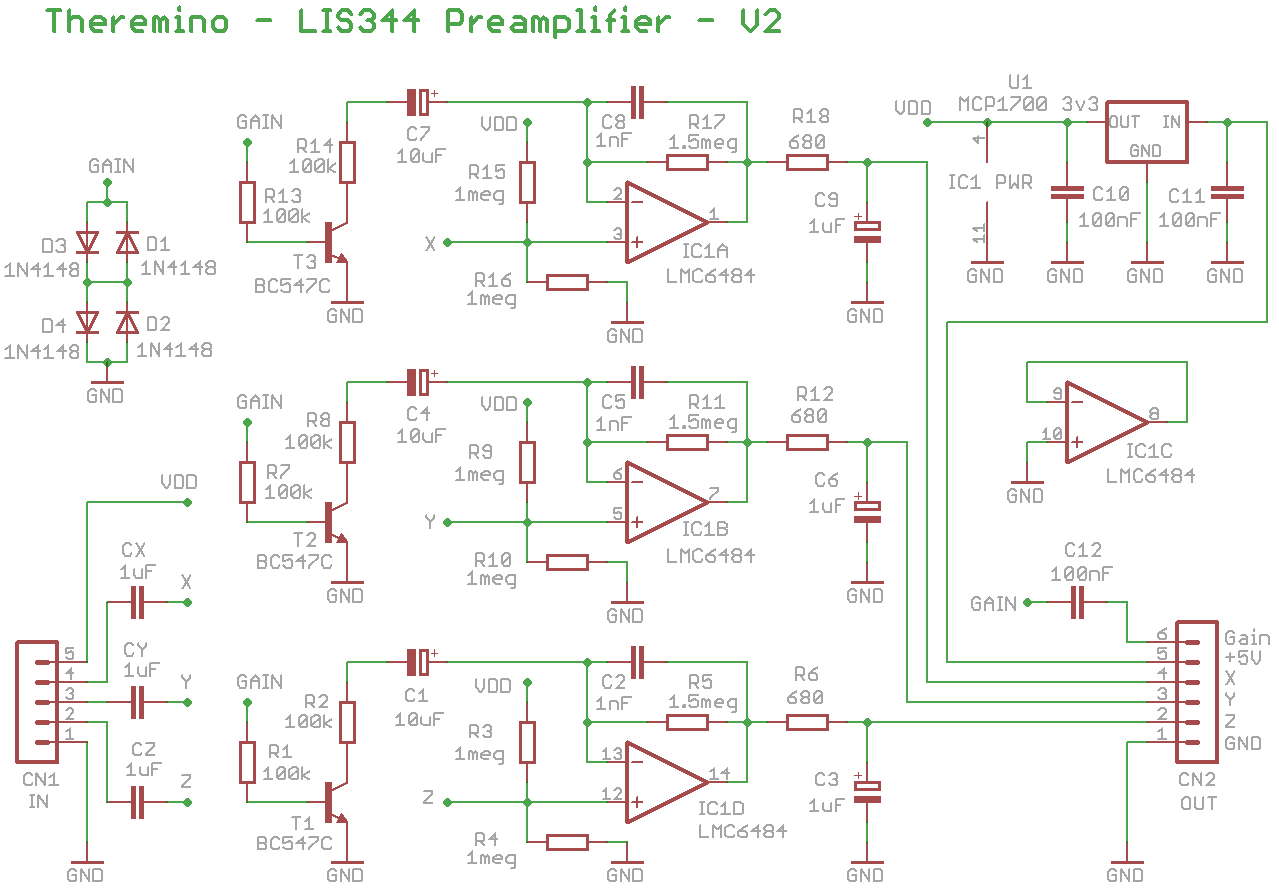
The gain is adjustable by means of a PWM signal. The gain varies from 1 (no gain) up to 15 times (about 25 DB of gain). The highest gain could also be enhanced by replacing the resistors R2, R8 and R14 with 33k resistors (maximum gain = 32 DB), or 15 k (maximum gain = 40 DB).
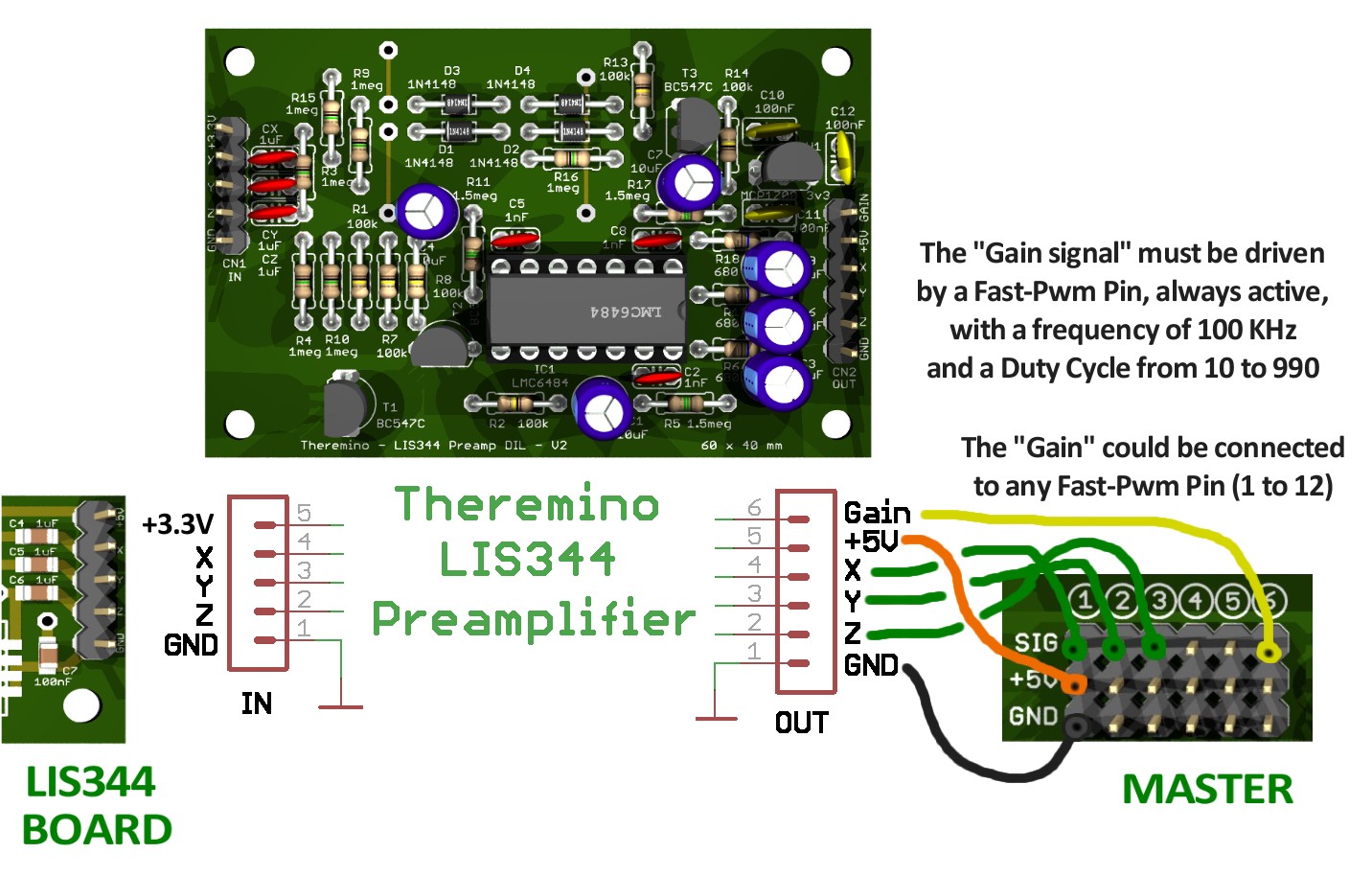
The signal “Gain” must be generated by a Fast-Pin Pwm. The PWM frequency must be adjusted to 100 KHz and the Duty Cycle range being 10 (minimum gain) to 990 (maximum gain). The PWM signal should always be present otherwise the unit is malfunctioning (distorts the strong signals).
With this second version, the inputs can be connected directly, both the coupon with multiple accelerometers (to reduce the noise) both accelerometers with LIS344, both three Geophones.
For connections, see the following three schemes:

Project download triple preamplifier:
LIS344_Preamp_V2.zip
Form with multiple LIS344
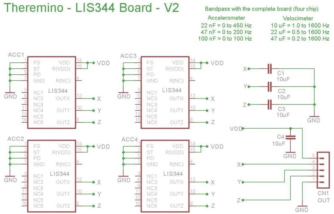
This module can accommodate from one to four parallel accelerometers. Given that the chips are cheap you can think of to put in parallel up to sixteen, by stacking four printed. With many parallel accelerometers is remarkable noise reduction. If you connect them to the preamplifier triple, or the new ADC 24, you get a Seismometer for earthquakes, small and cheap, but unthinkable for mechanical instruments of last century.
Adapter to connect the sensor with LIS344 to form Adc24
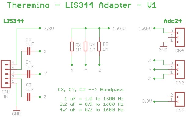
This adapter fits the inputs 13, 14, 15 and 16 and ….
UNDER CONSTRUCTION
Downloads of Eagle PCB, with diagrams and images to jpg.
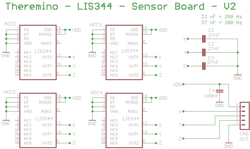
Module design with LIS344:
LIS344_Sensor_V2.zip
Project of ’ adapter for connecting all ’ Adc24:
LIS344_Adapter_V1.zip