
Geology

The geology is a complex science and huge… We invite you, to see the real experts of the community of geology, studying these issues for decades. Angel Dolmetta was Theremino system didn't exist when the digital acquisition systems and analogue acquisition systems, When the PC was not a computer but a producer of the festival with ribs and tortillas…
https://www.theremino.com/contacts/references#dolfrang
Magnetometers
Speakesensors produces the excellent magnetic sensors, FGM1, FGM2 and FGM3
www.speakesensors.com
www.speakesensors.com/PDF/detail.pdf
FGM_AppNotes

These sensors are real magnetometers, capable of measuring Earth's magnetic anomalies minimum. Working with a completely different principle, Hall elements found in phones and other small chips for helicopters and drones. Are very stable compared to temperature changes and are cheap too (about thirty euros). Can be connected directly to a standard system PIN Theremino. But attention that the links of the FGM-3 did not have a standard format.

1) Connect the FGM-3 to the Master, preferably with a stabilized adapter, They provide a voltage from 5 Volt stable.
2) Between the output and the Master signal pin, Add a resistive divider, to adjust its signal, from 5 Volts to our 3.3 Volts (1k series and 1.8 k to ground)
3) Program entry as FastCounter
Stabilized adapter
To power the FGM3, starting from the 5 Volt very unstable, from the USB, You can use a MAX1724 chip that, starting with a voltage from 2 to 5.5 Volts, provides a 5 Volt stable. The addition of a pre-remote controller 3.3 Volts, can further increase the voltage stability, USB voltage variations. If the pre-regulator will not need, just jump it with a piece of wire, combining C1 with C2. The maximum output current is around 150 mA, then with one of these adapters you can feed, up to ten sensors FGM1 or FGM3, they consume 12 but the one.
The first version contained an error (the voltage divider R1-R2 was on the wrong side) This is version 2, correct, smaller and improved screen printing.


This file contains the complete project Eagle, the Gcode for the cutter and 3D images of voltage regulator and adapter for FGM1 and FGM3: GeomagneticAdapterV2
Connections between FGM-3, Geomagnetic adapters and Master

To connect the FGM-3 to Geomagnetic Adapter, It is recommended to use a standard extension, with the male connector cut out and replaced with a female connector, soldered manually. The female connector must be good quality and must be connected to the FGM-3, with miswires, as shown in the image.
To connect the Adapter to the Master using a normal Geomagnetic standard extension. Just make sure to keep the black wire (GND) at the bottom (close to the edge of the plate).
The length of the extensions can be 15 cm, Sixty centimeters or even many meters.
Read the signals of Geomagnetic sensors
The signal of these sensors is a square wave, with variable frequency, from 40 KHz to 200 KHz (from 5 us to 25 us about). The only type of Pin, able to read such high frequencies, is the Fast Counter. Then in the HAL, programming the Pin as Fast Counter, and tick the box “Convert to frequency”.
Each individual module (master or slave), can read at most, a single Fast Counter. Then you can connect only one geomagnetic sensor. We do not recommend to add slave modules, one for sensor.
Connect up to ten FGM-3 to a single Master
The Master with firmware version 3.0 and subsequent, feature of the new types of pins “Slow Period”. All ten pins can be configured as SlowPeriod, but you have to pre-split the high frequency of each sensor, with a small CMOS divider.
The Pins “Slow Period” read the "period" (the time, between two successive fronts of salta, of the signal) with high resolution. The resolution is from 18 AI 24 bit, Depending on the sampling frequency (18 bits with 100 readings per second, 24 bit with about a reading per second). A single Master module can read up to ten magnetometers but you must pre-split the high output frequency, with cmos divider, and bring it down to about 1 Hz or less. So every FGM3 must have a small adapter (with a HEF4521 for example) before the Geomagnetic Adaper. To connect many FGM you can use a single Geomagnetic Adapter, but you have to route the signals apart. And connect each signal to the Master, with a resistive divider to 1 k and 1.8 K.
Gradiometer with two sensors
Two sensors (FGM1 or FGM3) can be mixed with a simple D-type FlipFlop and the output signal is sent directly to a system PIN Theremino. With this scheme, you get a “Gradiometer” very sensitive. For details of the construction mechanics read this article: FGM_Gradiometer. Do not follow the wiring diagrams in this document, with the Theremino system is much simpler. LM2917 chips, 4049, SCL006, SCL007 and AD557 don't need them and using them it would worsen the system's stability.
A great earthquake sensor with LIS344 modules
Accelerometers are great for seismographs, their frequency range from 0Hz at 50 Hz is ideal for detecting earthquakes. It is recommended to use the LIS344 for its very low noise.

Accelerometers are too noisy for micro-tremors, but are great for earthquakes, from zero degree in the Richter scale up, up to the strongest earthquakes, in one range. When connecting in parallel four or eight LIS344, the noise decreases further. Adding three capacitors, to limit the bandwidth, and then integrating them into software to get the speed instead of acceleration, You can go down up to -2 or even -3 the Richter scale.
Then with a few tens of euros (Master including) you get a good seismograph, digital sampling, directly connectable to the USB and self-installing (without installing drivers)
For details on connecting the LIS344 see page: hardware/sensors/accelerometers
Geophones

Connection of Geophones to module Adc24
If you have the form Theremino Adc24, Geophones are linked directly to your Pin, No add-in. Then in the settings of the Adc24 will adjust the gain that can be 1, 2, 4, 8, 16, 32, 64 or 128. Finally the Adc24 is connected to pins 7, 8 and 9 of the Master.
Connection of Geophones with GeoPreamp
With the GeoPreamp each geophone is connected to a Master Pin passing through a GeoPreamp. This method provides the least possible noise but the gain must be fastened beforehand with a resistor and can't be changed easily.
Connection of Geophones with triple preamplifier
The preamplifier triple, designed for accelerometers, It can also be used with the Geophones, as explained on this page. With this configuration the noise characteristics are worse than GeoPreamp, but you can adjust the gain and even change during operation.
Connection of Geophones directly to Master
Limited to the detection of events “Strong Motion”, You can link directly to the Master Pin configured as Geophones ADC16. But you cannot directly connect the two wires of geophone to Master, shown in the following diagram components are required.
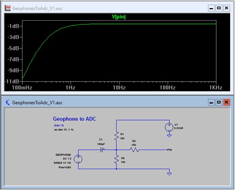 To link each geophone to Master, need three resistors 10 Kohm and an electrolytic capacitor from 100 uF, with voltage 6 Volts or greater.
With these components you get a bandwidth that extends down to about 0.2 Hz.
The tension of 3.3 Volts must be taken from one of the points marked “3.3” of the Master.
GeoPreamp
Update of the 2023.
What you will read below applies only to the classic Adc24 and not to the Theremino Adc24.
The Theremino Adc24 has a low noise input preamplifier that worthily replaces this GeoPreamp. Also has the ability to change the gain of the preamplifier, very comfortably, without having to change resistors, as you had to do with the GeoPreamp.
The premplificatori GeoPreamp have exceptional characteristics:
1) Incredibly low noise (ten times lower than that obtained with the best commercial systems with ADC 24 bit)
2) Minimum dimensions which allow to install them near the geophone and eliminate the noise caused by the connection cables.
3) Ability to auto-build them spending very little.
The following points help to minimize noise:
1) No digital sensor components
2) The incredibly low voltage noise (less than 10 Nano Volts on root Hz) of LT6014
3) The knee 1/f (the frequency below which the noise begins to increase) about 2 Hz, from ten to a hundred times less than that of normal low operational noise.

Here you see the result. The following noise at the entrance to the pre (He earns 1000 times) is about 0.2 UV.
An ADC to 24 bits would have a resolution of 0.2 but it's not just the UV digital resolution that matters. The ADC to 24 bit not having low noise analog preamp input and working closely with strong digital signals, have a high input noise. This results in the last two or three bits dancing. To control it just short the geophone and then be careful as there are bits that don't stand still. Even in more expensive equipment will never be less than three (then 1.6 noise UV) but just the smallest PCB design mistake to worsen the noise characteristic. The new magic word “24bit” to fix the noise, It takes an analog preamplifier.
In summary: The ADC to 24 bit, due to the latest bits that don't stand still, have a noise at least ten times greater than that obtained with l’ LT6014.
Make sure that all of our measurements are at the entrance of the ADC, then after pre-amplifier gain 1000 times. To get the values the geophone must divide the voltages for 1000. In practice the mV uV and decibels must subtract become more 60 DB.


In these two pictures you can see the comparison of the noise of a regular low noise operational amplifier (on the left) and the noise obtained using the LT6014 (to the right)


And here you see the same comparison but in the form of spectrum analysis. Note the knee of noise at 2 Hz that involves major improvements at low frequencies (where the Geophones are less sensitive) and the noise almost constant at about 0.2 UV, out of all the useful range.
A very low noise promotes better definition for all techniques that use micro-tremors of the Earth and allows to obtain, with the Geophones economical to 4.5 Hz, the same performance achievable by Geophones from 2 Hz or 1 Hz, that would cost from 10 at 100 times more.
– – – – – – –

This YouTube video shows the micro movements of the Earth and the passage of some cars at a distance of 50 meters (the strongest) and 250 meters (the weakest) : http://youtu.be/aKd25fwnE8o
Geophone Preamplifier V2
I test this version showed a substantial improvement. With the coupling of the first step in continuous disappeared the 10uF capacitor on input. Noise and sensitivity to mechanical disorders are eliminated and noise, measured with spectrum analysis, has dropped by at least ten times at low frequencies (region where the Geophones are more deficient)

Note that here the full scale is 1 UV (amplification for 1000) and that instead, in testing the previous version, they used a full scale 2 UV.
A realization fully SMD

The PCB to 16 x 23 mm (in single face and no jumpers) is not just an exercise in elegance. The small size minimize noise and microphonics uptake, due to twisting of the components. The tracks large and well isolated from each other, increase reliability. The module is small enough, they can be insulated with a heat-shrink sheath and positioned “along the wire”. Soft silicone wires and the transparent sheath can be found at HobbyKing. A soft foam filling, held in position the PCB and will prevent it from pounding against the metal walls.
PreampGeoV2 project downloads


This is the complete design of PCB (CadSoft Eagle project), schematics, Assembly plans, LTSpice simulation and 3D images.
GeophonePreamplifier_V2 (zip file from 500 Kbytes)
– – – – – – –
>>> Message to car-builders and aspiring entrepreneurs <<<
All our projects are free and you can make them and sell them at will, but be careful to make programs that include big gains. To avoid unnecessary costs and future disappointments, We advise you not to schedule a for-profit production.
The new versions will include substantial improvements, including a greater resistance to saturation and a faster recovery after strong saturation events. An interesting idea suggested by Angelo Dolmetta, It will also set the gain so easy.
Geophone Preamplifier V4
This is the final version. The sensitivity to mechanical disturbances and noise at low frequencies are minimized. In the area below the 5 Hz (region where the Geophones are more deficient), There are no components with lower noise of the LT6014.


The small size minimize noise and microphonics uptake, due to twisting of the components. These extra touches, combined with the use of LT6014, minimize noise, in the area of low frequencies. Than an ADC to 24 bit, the LT6014 has a considerably less noise. An ADC to 24 bits would have the advantage of not requiring the selection of gain but, in our opinion, the important thing is to minimize noise. Having to preselect the gain, There seems a good price to pay for having the least possible noise.
– – – – – – –
This is the complete design of PCB (CadSoft Eagle project), schematics, Assembly plans, LTSpice simulation and 3D images.
GeoPreampV4 (zip file from 2.3 MByte)
Theremino GeoPreamp_Tester

This application, In addition to test Geo Preamp, serves as an example of test apparatus. As it known, We're pretty picky. So we set the software to be very finicky. The button “Save report” you enable only if the parameters are respected within the following limits:
- The value of zero is greater than 498 and less than 502
- The gain is greater 80.0 and less than 80.9
- The noise is less than 0.019 UV
- The pulses are positive (check that the Red-Black wire is not contrary)
The software produces very narrow pulses (They then contain all frequencies up to the inverse of the pulse width) and perform a spectrum analysis, to obtain the gain and bandwidth. In another phase does not produce pulses and measures the noise.
Each time you launch the software you must connect a known good GeoPreamp and with known characteristics. Then you have to press “Ref. input” and wait about a minute until the beep. Then you press “Reference” and you wait another minute. Possibly you should also pay a fine calibration of the boxes “Zero offset value” and “Trim zero ref.”. Calibration makes measured values, as similar as possible to those of the sample (but there are subtleties, It is a few tenths of decibels). From this point on, the meter is ready to try the GeoPreamp as per list:
- You connect a GeoPreamp to try
- You press “Response test” and you are waiting for the beep
- You press “Noise test” and you are waiting for the beep
- You control which “Serial number” It's fair and you press “Save report”
For every GeoPreamp it takes little more than 30 seconds. Sometimes the graphs are not well, or in doubt. In these cases you can press buttons “Extend test” and prolong the test also repeatedly. If the test is not passed manually test buttons are disabled and we start the list with a new GeoPreamp.
GeoPreampTester – version downloads 1.4
Theremino_GeoPreamp_Tester_V1.4_WithSources
Test hardware

Here you can see how it is done the hardware to test Geo Preamp and as we simulated a geophone “free float” (without reference to ground).
The test fixture should be fully shielded, our seems an iron, has two hinges and a copper lid with a pomellone to open it and close it. Internally there is also an led for half a watt, to read the serial number and pressure fittings, easy to attach and detach GeoPreamp. During the test, the device must be closed, otherwise disturbances collected by environment do not pass the test.
Weekly report files
Inspection reports are available in the first batch of about 50 GeoPreamp. Their serial numbers currently are from 286 at 327. Don't start at zero for several reasons:
– The first thirty (about) pre-series prototypes were welded by hand.
– The first who passed the test were taken from the container from above.
Those wishing to download the report of his “Preamp” Use this link to open the page for the serial number 300. Then just change the “300” (in the address bar) with the number that you read behind the circuit board and press Enter.
https://www.theremino.com/files/GeoPreamp_Tests/GeoPreamp_Serial_300.jpg
These reports are pretty much all the same and therefore quite useless for users. But ensure that the pre have been tested individually, and within the design features.
Theremino GPS
This application greatly simplifies the reading of GPS sensors.
Here we show only some images while the instructions are in the HELP file that you download with the application and that you view by pressing the HELP button of the application.
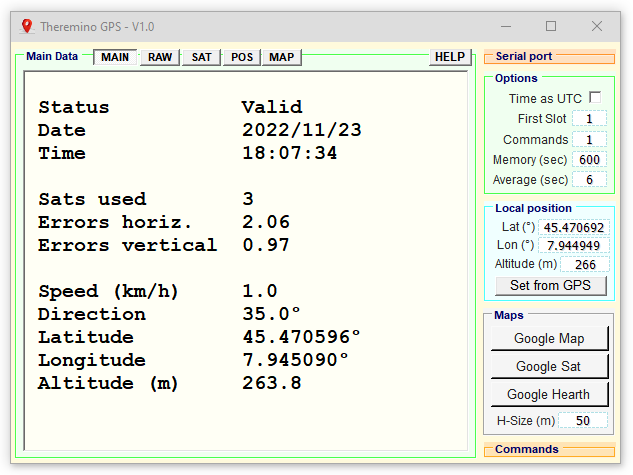

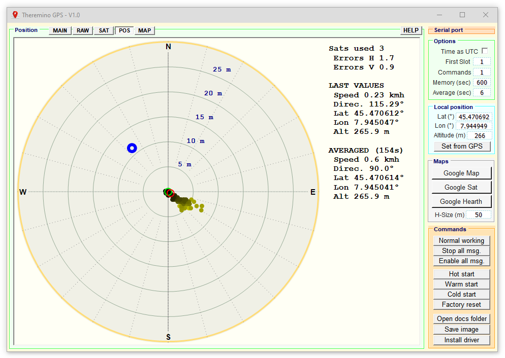
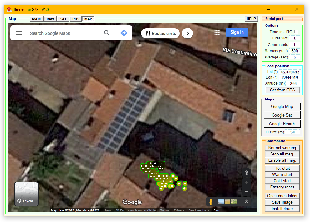
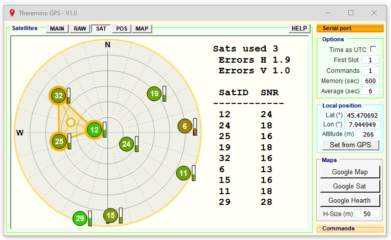
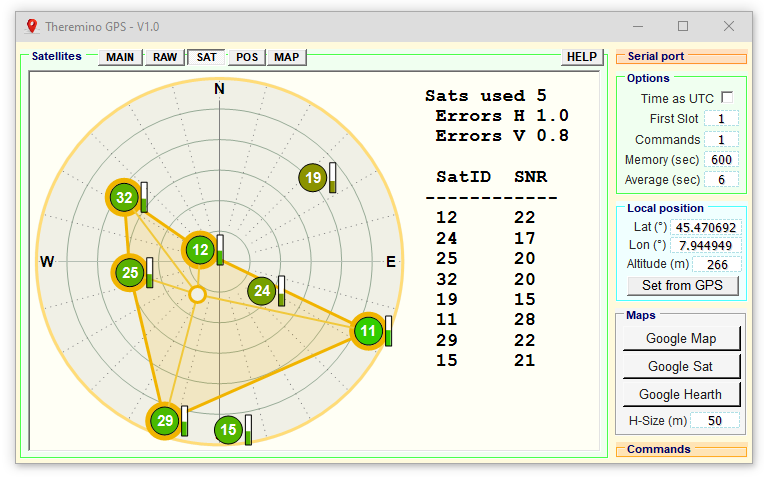
The first five images were taken with the sensor in a laboratory located on the ground floor, with two floors of house above and moreover of an ancient house, built with stone walls from 70 cm. So the inaccuracy of the coordinates is many meters.
It is remarkable, however, that even in this situation the sensor was able to pick up the signal of 8 or 9 satellites and with a fairly good signal-to-noise ratio. With the sensor positioned outdoors you get much higher accuracies, even less than 30 cm.
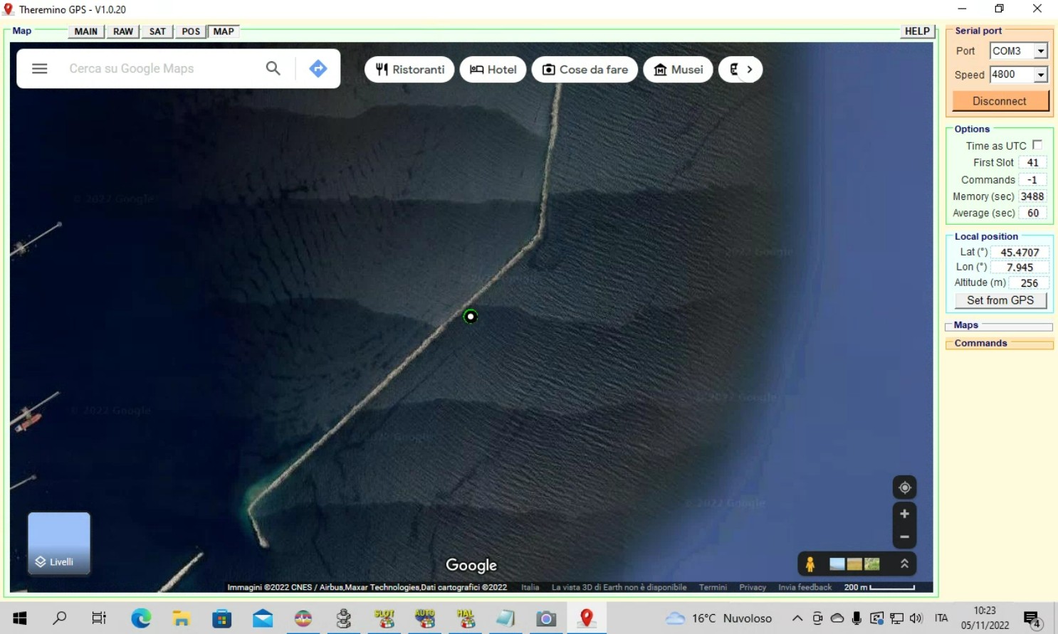
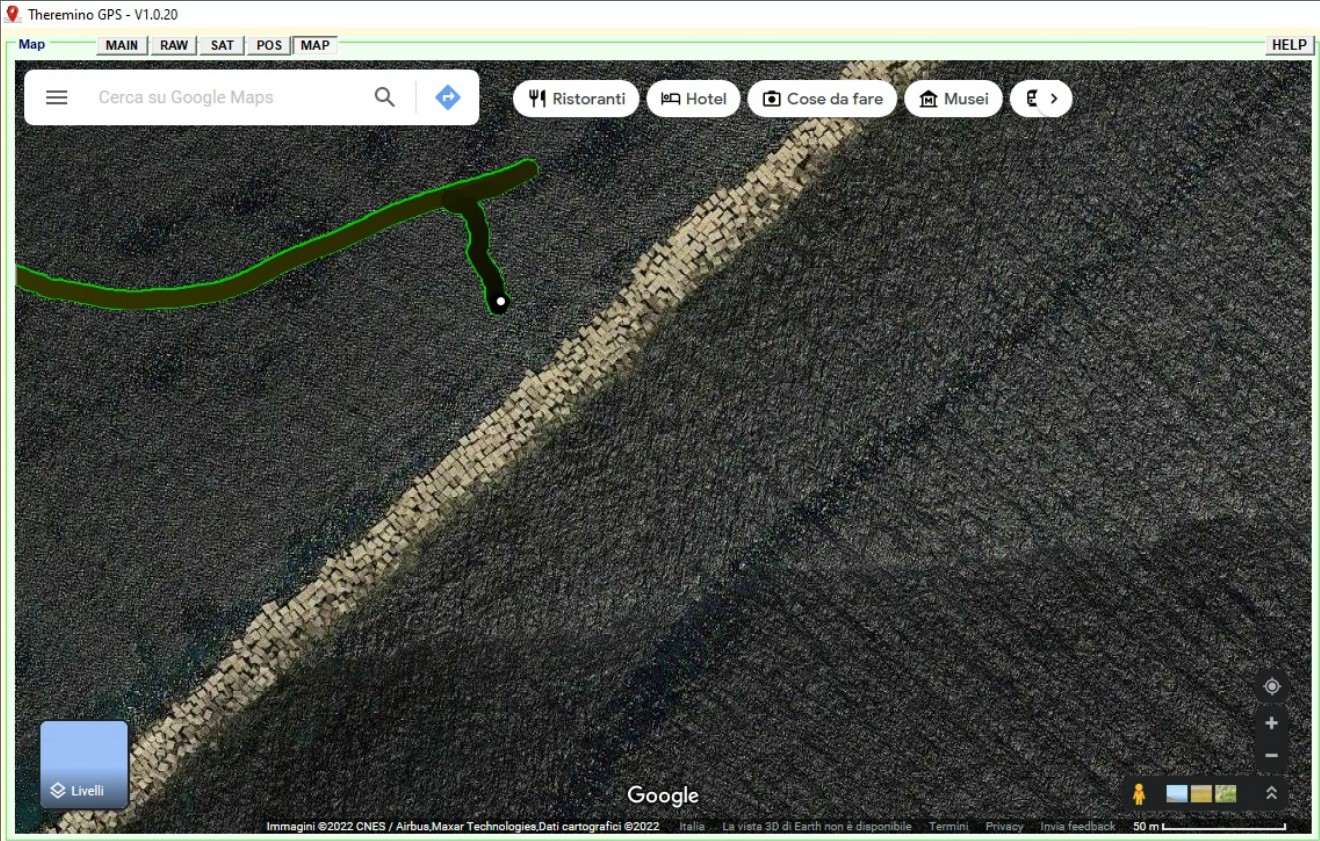
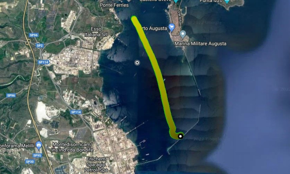
The last three images show some routes in the port of Augusta (Sicily), during a water sampling campaign. The samples were done on ships and floating pontoons with the Nemo system based on applications and In-Out system Theremino. For information on the Nemo c systemHiedete to our collaborator Marco, who designed it.
Notes for versions
- Version 1.1
We've added the option “Allow navigation” in the Panel “Options”.
Keep this option disabled in normal operation to prevent Google from opening annoying messages.
But in some cases you have to activate it, for example to accept Google's Privacy.
Download Theremino GPS
Download Theremino GPS – Version 1.1
Theremino_GPS_V1.1
Theremino_GPS_V1.1_WithSources
For all systems from Windows XP to Windows 10, both 32 which in 64 bit (Linux and OSX with Wine)
GPS Modules
A road often followed is to include GPS receivers in devices of detection of movements but the following considerations advise against this solution.
1) To the same PC can be connected (at the same time or at different times) different sensors for earthquakes and micro-earthquakes and everyone needs a synchronization with UTC time (Coordinated Universal Time) May then occur overlaps and unnecessary additional expenses or, on the contrary, finding yourself without synchronization.
2) Movement detection devices are often found in the basement very long antenna cables, forcing me to install that mitigate the GPS signal and performance decreases (belated revelation of the satellites and fewer satellites contemporaries)
3) The presence of additional electronics in the same detector device, increases the electrical noise right in the most sensitive point of the whole chain.
We therefore decided to advise against GPS detectors but always use the comfortable and cheap GPS receivers that plug into a USB port.


GNSS models cost a bit’ more but are better, They also use Russian and Chinese satellites and can synchronize even if the antenna is covered by walls or trees..
However, if at the beginning you place them in an open area and wait a bit’ of time, then all models can also work in positions “Impossible”, we also tried indoors on the ground floor with two floors above and went, with precision a little’ Poor (tens of meters), but they went.
If the sensor is positioned well, facing upwards and with the sky totally uncovered, you get to very high accuracies and stable indications, around the 30 centimeters and even less.
You will find annotations and links for these forms in the folder “Docs” of the application.
Geoelectrical data surveys
We are designing a device for measuring the resistivity using the method most used, to 4 electrodes.

Basic scheme plans to enter a direct current through two electrodes, traditionally called “A” and “B” and measure the voltage between the electrodes “M” and “N”. Knowing the current, the voltage and the distance between the electrodes, the soil resistance according to formulas (usually Wenner and Shlumberger)
This method is based on a patent of 1957 (expired from fifty years) and therefore freely usable. For those interested here is the original patent: US2796235
The electrodes are simple pegs, on the picket lines A-B you enter a variable voltage from 0 to 500 Volts (Depending on soil resistivity) in order to produce a sufficient current for a precise fit (normally in the range of 0 to 10 Ampere) On the picket lines M-N maximum voltages are measured +/-5 Volts (to be measured with a voltmeter differential)
Manually moving the pegs you can also build three-dimensional tomographic maps. Some devices allow you to have a number of pickets at the beginning and then switch them according to predefined sequences. Are switching relays. The main switching, always needed, need to swap the electrodes M and N and make a second voltage measurement in order to eliminate the error caused by the spontaneous potentials.
It is not difficult to design a low-cost device for these measures based on the system Theremino. But before we get started we will collect the required characteristics and make the right choices to arrive at a simple project, effective and inexpensive.
Switching of pickets
To switch the pickets using two methods: Or using intelligent pickets switches themselves, on the four M-N-A-B, with a logic control. Or do i use single wire, one for picket, and all switching operations in the main container.
Smart pegs have been patented in 2005 and then the patent will remain valid for the next twelve years, Here he is: US20050078011

In this picture you see the schema of an intelligent picket, We won't use this method, and because it is patented, but above all because it involves placing a lot of delicate electronics in the vicinity of the same picket (the damp and the), making everything very expensive, delicate and difficult to repair in the field. In addition this method involves carrying around an expensive seven-pin cable.
The alternative is to bring a single core cable for each picket and do all the switches in the main container.
Number and type of relay
Whether you're in smart or pickets relays together in the main container the number of relay does not change, are always four relays for each picket. This means that for only 24 pickets use well 96 relè. You can not use solid state relays (with active components) because they have a leakage current too high for voltage measurements and, at the same time, struggle to withstand high voltages. Probably you should use relays with different characteristics, the first type appropriate to the excitement A-B and the second for the weak strain M-N.
– – – – – – –
Found the solution for switching
This elegantly solves all problems solution. It consists of identical modules to be connected directly to each other. It only takes three wires to control any number of relays so just only one Master Theremino.
PIN1 - Output - Pwm16 - Pin2 output voltage control - Input - Adc16 - Measurement of output current Pin3 - Input - Adc16 - Voltage measurement Pin4 - Output - Digout - Enable Pin5 - Output - Digout - Date Pin6 - Output - Digout - Clock

The single module is all part dashed that includes four relays and a shift register and provides an output for a picket. This is a PCB from a few centimeters with identical inbound and outbound connections. It becomes so easy to connect them to each other and add a number of channels also very high.
The modules should be placed in the main container. It is not recommended to place them near the picket lines because the cable would become too delicate, sensitive to moist, difficult to repair in the field and expensive.
Great news US20050078011 patent does not cover our method
Fortunately the patent specifies a method based on a packet of data that is changed by a microcontroller present near every picket. So our shift register (It is an ancient technique used in automation for many years) is not included in “claims” of the patent (which for convenience we copy below)
Summary [0010]
Instead of assigning a unique address code to each switch in a series of take-outs on a multi-conductor cable, each electronic switch is programmed with the same address code. That is, each switch is programmed to be activated. When it receives a command queue that, for example, is prefaced with a particular address, eg the number 1. The second part of the code (y) instructs the switch as to which conductor in the multi-conductor cable is to be connected to the local electrode at the location of the switch. When the controller issues a code command that is prefaced by a number which is larger than 1, (eg n), then the first switch in the sequence of switches along the cable decrements the preface number. The first switch then re-transmits the code command, with only the preface portion having been changed, (i.e. to n-1), along the cable to the next switch in the series. Each successive switch performs a similar modification to the preface number, and retransmits the progressively modified code command to the next switch in the series. Ultimately, when the modified command reaches the nth switch, it is prefaced with the number 1, whereupon that switch then recognizes it as a valid command to operate. The second part of the command (y) remains unaltered through the repeated re-transmissions, and determines which conductor in the cable is to be connected to the electrode (i.e. to ground).
Claim “A”
A controller for transmitting a coded command signal having a first portion that is modifiable to identify a specific take-out location and a second portion for identifying a specific conductor of said cable to be connected to ground.
Perché l’autore di questo brevetto è andato a specificare un metodo così complesso quando avrebbe potuto invece definire un metodo generico per commutare i relè? Perché altrimenti sarebbe ricaduto in metodi precedenti, arte nota da gran tempo, come il nostro semplice “shift register” and then the Patent Office would have considered “public domain” and he wouldn't have registered.
Advice for those who write patents: be increasingly vague can. If you specify too, (as in this case) then many people might make slightly different projects (as our) and exit “claims” of the patent. On the other hand, If you specify too little, There is a risk of seeing him decline by the Patent Office.
According to counsel for people who want to write a patent application: Don't do it! Patents, If not supported by a powerful and oodles of cash, are worth less than the paper they are written. Corollary: Patents explain what competitors do not have to do, and are the best way to help them do similar things and not give you the same money.
A complete system for polls geoelectrical data
Here begins the complete system design. We begin with an overview of the individual modules and. The system appears complex, but is modular and easily accomplished, also on matrix Board, public and economic components.

- (A) The ThereminoMaster is the link between the USB and the signals of InOut.
- (B) The ThereminoDualPsu converts 5 Volts coming from the PIN 1 of the Master, in two voltages stabilized (3.3 Volts positive and negative) necessary to the module (And)
- (C) The ThereminoDualHvPsu converts 5 Volts coming from the PIN 1 of the Master, in two voltages stabilized (up to +/-50 Volts) necessary to the module (And)
- (D) Thel ThereminoPwmToCV converts the PWM signal coming from your PIN 1 of the Master, in switched DC voltage (classical running), or sine wave variable from 1 Hz to 80 Hz (high precision and low power consumption)
- (And) The ThereminoGeoDriver boosts the signal and sends it to the points A-B, with varying widths up to 100 Volt p.p..
- (F) A ThereminoVoltMeter (measuring differential amplifier) measuring excitation current of picket lines A-B and sends it to Pin 2 of the Master, configured as ADC.
- (G) A ThereminoVoltMeter (measuring differential amplifier) measure the voltage coming from the points M-N and sends it to Pin 3 of the Master, configured as ADC.
The form G is the Theremino Differential Meter that you use for other projects, but optimized for geoelectrics, with the following values:
R1 = R2 = R3 = R4 = R5 = R6 = 1 Mega
R7 = R8 = R9 = 100 K
Trimmers from 47 K
In a basic unit, A-B and M-N signals go directly to four pegs and Clock signals, Date and Enable are not used. A unit with the switching of pickets will use instead all signals. Modules for changing over the pickets are illustrated in the next section.
Download – Here you can download the complete design of PCB (CadSoft Eagle project), schematics, Assembly plans, LTSpice simulation and 3D images:
GeoElectric_Modules_V4
(for convenience this file includes all the modules even if some were developed for other uses and are already present in other sections of the site)


This latest version GeoMeterV2 has optimized components according to current best estimates. The PCB is still the same.
The GeoMeter included in the ZIP of geoelectrical is similar to DiffMeter, but optimized for the geoelectrical. This GeoMeter has the PCB slightly larger, four holes to secure it with the other modules and component values appropriate to the geoelectrical.
Comments on the first version: This version is basic and robust, use it in the coming months to the first tests but we're already thinking about replacing three modules with just one. This is possible Thanks to the modularity of the project. The modules B-C-E will come together in a single GeoDriverPlus, It will work simultaneously from survoltore and from class-D amplifier, with total efficiency 90% The new version will allow tension (or current) more than doubled, always starting from the wretched 300 or 400 but withdrawn from USB. Or, everything else being equal, the batteries will last twice. A note of 2013/06/11: Working in sinusoidal alternating and you do not need to inject a strong current. Current savings you would get with the class D, does not justify the complication and the inevitable disturbances caused by switching operations. Then do not continue with the design of the GeoDriverPlus.
Modules for switching pickets
You must create one form per picket, the number of modules is virtually unlimited can also be connected 500 modules without problems (Apart from the final dimensions and the time to build them)
Whatever the number of modules (pickets) only one Theremino Master manages to operate both switches modules of all stakes and all modules from the previous section.
The component cost is low (a few euros per module, PCB including). The problem is the time it takes to mount them. A set of 24 or 48 modules can easily request one week job.
All components are placed in step 2.54 mm and the upper slopes of facccia are actually wire jumper. Then these modules can also be constructed out of a thousand-holes.
Modules plug one another with standard extensions. Sure that the female connector must be turned, a penalty system unstable and unusable after a few months of wet. To avoid mistakes, read this page: www.theremino.com/technical/connection-cables
IMPORTANT CORRECTION (without which the operation is unstable)
In the two following versions, the value of R8 and R9 must be changed
– R8 = 4.7 k
– R9 = 22 ohm resistor
Version with standard relays


This is the first version, probably not final. There are doubts about what relay use. Reed Relays would be smaller and may be fine. A requirement is also that they are readily available. We are also exploring the road of mosfet solid state relays. (After a lot of research on Farnell and Mouser it seems that no solid state relay has the features you need: voltage greater than 100 Volts, current greater than 100 mA, resistance less than 5 ohm resistor, capacity less than 10 PF and unit price is less than 2 Euro. If anyone knows of a suitable write)
Download – Here you can download the complete design of PCB (CadSoft Eagle project), schematics, Assembly plans, LTSpice simulation and 3D images:
GeoSwitcherV1 (preliminary version, the relays are replaced with several smaller ones)
Version with reed relay


Reed relays have contacts in a vacuum glass bulb, are smaller, they cost less and consume only 10 mA, against the 20 or 40 but normal relays. It is therefore recommended that this version.
Download – Here you can download the complete design of PCB (CadSoft Eagle project), schematics, Assembly plans, LTSpice simulation and 3D images:
GeoSwitcher_ReedRelays (version with reed relay)
Cercametalli
We are planning an SDM (Software Defined Metal-Detector)

Pin Pointers
The Pin Pointer is necessary during the excavation work but unfortunately the good ones cost a lot and the cheap ones have disappointing characteristics. Here is a comparison between the two most popular models.
- Garrett Pro Pointer – Costa 129 Euro and hears a coin from 50 cents to five centimeters.
- GP Pointer – It is also found less than 15 Euro and hears a coin from 50 cents to two centimeters.

We did the tests on a GP Pointer from 2021, which on eBay stated how “new version, high sensitivity”.
Older models may be built differently so we advise you to look for the ones that say explicitly “high sensitivity”.
Features in comparison
The construction characteristics of the GP Pointer are good, the mechanics are identical to that of the Garrett and the electronics are also well designed. They both use a 9 volts and consume roughly the same current, about twenty milliamps, which allows you to use them for about fifteen hours. But beware that neither is truly waterproof, you can also use the front for digging, but the part that is held in the hand must not get wet.
The only problem with the GP Pointer is sensitivity, so we did some tests and found how to fix this defect in a simple and effective way.
The poor sensitivity of the GP Pointer is due to two factors. The first is an assembly error and the second is a slightly zero point adjustment’ poor in the firmware.
Increase the sensitivity
First of all,, using a strong backlit lamp, we check the distance between the sensitive coil and the tip.
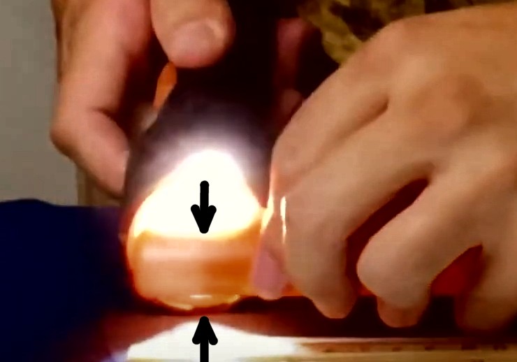
All these pointers are badly set up, sometimes there is a centimeter of light between the coil and the tip, sometimes even two or three, like in this picture.
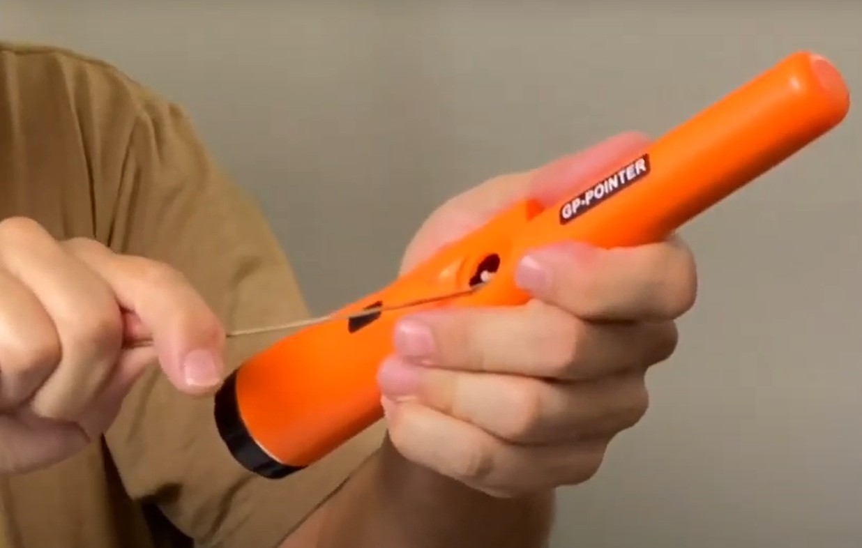
Then we will remove the ignition switch rubber (just pull it to one side and it comes off easily).
And finally, using a metal rod of 2 mm slightly arched, we will push the reel until, checking with the lamp, no more light is seen between the coil and the tip.
With this fix it comes around 4 centimeters which are an average sensitivity, suitable for all situations and you might as well stop there.
Be very careful not to force the internal button,
because you just need to push it a little’ sideways and disassembles.
If you happen to disassemble the button then then you have to be really skilled to put everything back in place. This is the sequence and they are all difficult and delicate operations:
- Open the battery holder and unscrew the screw.
- Gently pull the battery holder with pliers.
- Pull again, but without tearing the bobbin threads, until everything is extracted.
- Fix button (reposition its spring, its button and the cover).
- Put everything back into the orange tube, making sure that the PCB slides into the guide.
Adjust the sensitivity
With this second correction we will also be able to overcome the characteristics of the Garrett. We will get greater sensitivity (even an inch or two beyond Garrett's maximum distance) and we will be able to adjust the distance from a minimum of about 2 centimeters up to a maximum of six or seven centimeters.
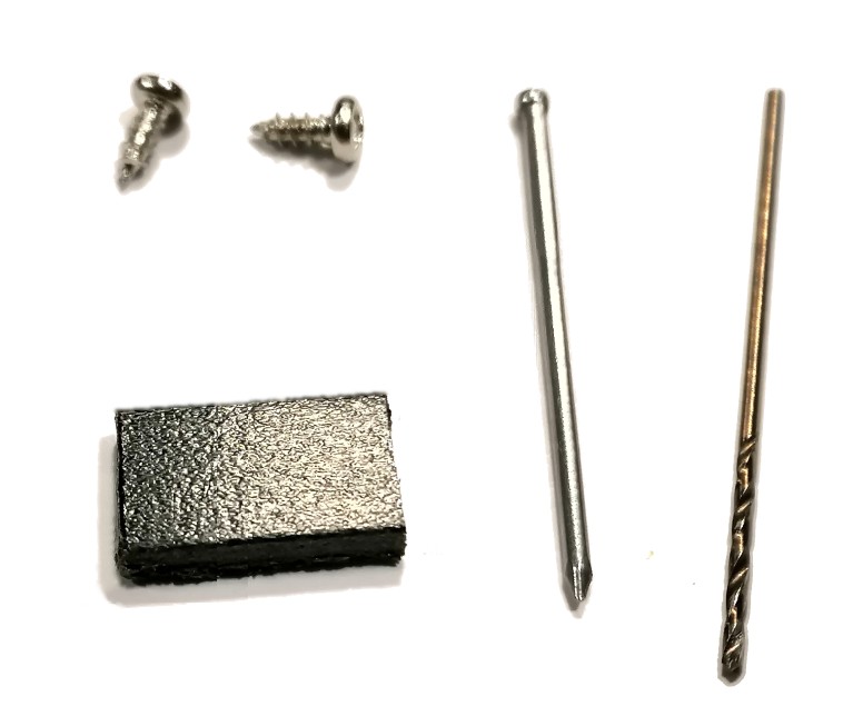
We will need these materials:
- Two parker screws from 2 mm in diameter and long 6 mm
- A piece of black plastic from 12 x 8 mm and thick 3 mm
- A nail of approx 1 mm in diameter and long 30 mm.
- A tip from 1 mm and a small drill.
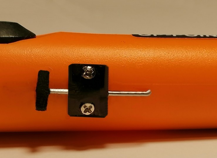
We start by gluing a piece of black plastic on the head of the nail. This handle will be used to adjust the position of the nail with the thumb.
Then the plastic block is pierced with a tip of the same size as the nail and checked that the nail runs well, making only a slight friction.
If the nail makes too much friction it goes over a little’ the hole with the tip, if, on the other hand, he does little, he squashes the plastic on the underside that will not be seen.
Then they make two holes from 1 mm at about seven millimeters from each other, first in the piece of black plastic and then, using it as a template, also in the orange plastic of the pointer. In the piece of plastic the two holes will also be countersunk with a tip from 4 mm (just over the diameter of the screw head).
Make the two holes in the pointer more or less in the position indicated by the photos. These holes will then be used to insert the screws. But be careful, two millimeters are enough, do not let the tip in too much because otherwise you could ruin something. In that area there are no components but be careful all the same because shortly before there is the printed circuit and along the tube there are also the wires that go to the terminal coil.
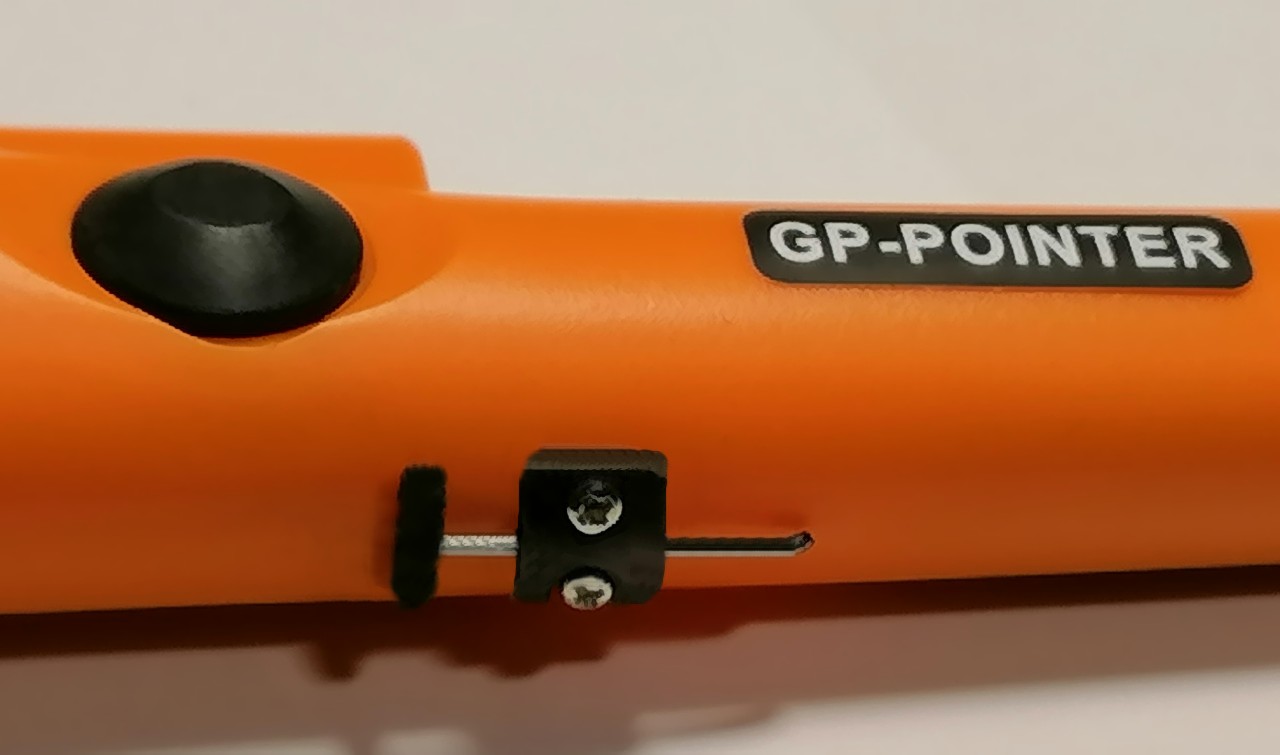
If you build it well you can easily adjust it with your thumb in the following positions:
- Turning on the pointer regardless of where the regulator is, the sensitivity will be set to an average value of approximately 3 or 4 cm.
- Pulling the knob all the way back will lower the sensitivity to approx 2 cm.
- To obtain maximum sensitivity, push the regulator forward until you hear the sound and then pull it back a little until it stops.
With fine adjustment, exactly on the edge of sound, we got a sensitivity of up to almost eight centimeters for a fifty cent Euro coin, thus equalizing the performance of the more sensitive and extremely expensive models that are seen in the test su YouTube.
The previous adjustment is unstable and the eight centimeters do not last long but in normal use such a delicate adjustment will not be necessary, just get up to the sound and come back a bit’ back, without too much attention. A sensitivity of 5 or 6 centimeters which is great during excavations.