
Stepper motors (Steppers)

ATTENTION: To enable the Pin type Stepper, Stepper_Dir and Pwm_Fast you must use at least the version 5.0 the HAL, and the form Theremino Master should be updated with the firmware 3.2 or later.
To find out what firmware you have just use the latest HAL, connect the Master and count the pins. The original firmware only had six pins, from version 3.2 they 10 and since version 4 they 12.
The latest firmware (4.0) Add six new Master Pin (passing by 6 PIN to 12 PIN). Therefore, with every Master module, You can control, from three engines plus six generic pin up to five engines plus two generic pin. Optionally you can add additional masters and Slaves.
Stepper control features with firmware Theremino:
- Ultra management-simple thereminico style.
- The software must send only one given, the destination in millimeters (Note 1)
- Useful working range from -10 to +10 Km (kilometers) (with steps for mm = 200)
- Managing up to five axes CNC machines.
- RepRap type machines management up to six engines (x, y, z, According to z gantry and two extruders). You can then extrude two colors.
- In addition 65 KHz maximum frequency on all five engines simultaneously (Note 2)
- Jitter of less than 20 nano seconds (Note 3)
- Adjustable maximum speed (from 1 to 18000 mm/min) (Note 4)
- Adjustable maximum acceleration (from 5 to 1000 mm/s/s) (Note 4)
- Audit reports the position reached, in millimeters, for each axis (Note 5)
- Possibility of using independent or coordinated axes in 2D and in 3D (Note 6)
- With coordinate axes in 2D or 3D, Write applications to control made easy. You do not need to calculate acceleration and speed. You can send simple target commands, in millimeters. (Note 7)
- Pulses with automatic width. Operation is simplified and doesn't risk step loss, caused by an incorrect setting of this parameter. You can use photo-couplers lenses, If you limit the max speed (Note 8)
- Automatic polarity. Operation is simplified and you avoid step loss, caused by incorrect setting of this parameter (Note 9)
(Note 3) As comparison: Mach3 has a Jitter 500 times greater (from 2 to 15 us depending on the PC). Have a very low Jitter, allows you to work at maximum speed without risking losing steps. Timing defects than Mach3 are well explained in this article.
(Note 4) The firmware protects the motor from each error. If your PC stops responding for some time, the firmware slowly comes, without losing steps. The same applies if the data is sent with irregular timing or contain errors.
(Note 5) The software can read the missing distance, every millisecond, for each axis and with high precision (fraction of a thousandth of a millimeter). You do not need to use this information, but some applications may find it very comfortable. May be useful for diagnostic purposes, or for algorithms that must meet a specified tolerance. With this information the software can work with closed loop and always at maximum speed. Continually checking distance of each engine by the target, the software can slow down exactly when you need it, without doing complex calculations of speed, trajectories and accelerations.
(Note 6) In version 5.0 the HAL axis coordination is not complete. Important applications take care of themselves, We are therefore focusing on the CNC Theremino application, and only after we finish the axes coordination.
(Note 7) The intermediate destinations are reset, up to 500-1000 times per second. The best route, is continuously recalculated. The control algorithm takes into account, the actual positions from each engine and maximum acceleration that can withstand. Although the CNC application calculates wrong path, you avoid in any case to lose steps.
(Note 8) Usually you have to specify the width of the pulses (with Mach3 from 1 to 15 uS). This is a poorly understood and many users regulate it randomly. Use wide pulses allows placing electronic devices lenses, as some photo-couplers (for example the cheap 4N25, 4N26 and 4N27). But baggy impulses restrict the maximum usable. Theremino rule this time 50 uS (allowing you to use sluggish electronics for slower machines), but reduces it automatically if you use high speeds and high values of microstep. To a minimum of 7.7 uS, When using the maximum frequency (65.535 KHz).
(Note 9) With other pulse generators (such as Mach3) you have to specify the polarity of the pulse. In order to set it you must know if the driver acts on the rising edge or descent. This information is not always available and if you get it wrong can happen sporadically step loss, very difficult to spot. Theoretically using the wrong front should not cause any problems, because at every rising edge, necessarily follows a falling edge. But, If the direction sign is updated at the wrong time, may lose steps, or take additional steps. The firmware of Theremino Master controls the direction sign with care. The signal can also be used to drive drivers (a minority) acting on falling edge. Eliminating this adjustment, the use is easier and eliminates the risk of losing steps.
Set the Pin type Stepper in application HAL
Each stepper motor needs two physical Pin, one STEP and one for the management. The microcontroller would place the Pin to pleasure, but we decided to limit confusion, by specifying preset positions, for Pin-type Stepper and Stepper_Dir.
The Pin type Stepper reading from a value, which is simply the destination in mm. Simple applications, can specify a destination far away, and let it do all the firmware. Most demanding applications, can calculate their own path and send frequent intermediate destinations. With this technique, an application can check the working speed (feed), and determine precisely the path, even in multiple dimensions. To get smooth motion just 20 destinations per second (up to 50 for the most demanding applications).
Reverse an axis:
To reverse the direction of movement of an axis, they swap the values “1000” and “0”, of boxes “1000 means mm” and “0 means mm”.
Specific parameters of the Pin type Stepper:
Max Speed – This is the fastest speed, in millimeters per minute. The firmware continuously checks the destinations sent by software. If the software is asking too much for the engine, the firmware restricts his speed, to avoid losing steps. Raise this value until you see that the motor will lose steps (It makes a high pitched noise and stops) and then decrease it by a 20..50%, to return to a safe area. Repeat the tests under load, or by braking the motor manually, so make sure you have some room.
Max Acc – This is the maximum acceleration (and deceleration), in millimeters per minute. The firmware continuously checks the destinations sent by software. If the software is asking too much for the engine, the firmware restricts its acceleration, to avoid losing steps. Raise this value until you see that the motor will lose steps during changes of direction (It makes a high pitched noise and stops) and then decrease it by a 20..50%, to return to a safe area. Repeat the tests under load, or by braking the motor manually, so make sure you have some room.
Steps for mm – Here you have to set the step, the engine is in a spin, multiplied by the microstep, set in the controller, and divided into millimeters, produced by a rotation of motor. If each spin, produces a millimeter of movement, and the engine is a 200 steps per revolution, and don't use the microstep, then you set the value: 200 (steps per revolution) x 1 (microstep) / 1 (mm per revolution) = 200. If using sixteen microstep then you set the value: 200 (steps per revolution) x 16 (microstep) / 1 (mm per revolution) = 3200.
Linked to previous – By enabling this check box, the motor is connected to the previous, and is therefore part of a pool, running 2D tweens, 3D, 4D or 5 d. Without this interpolation, the engine needs to do less road, arrive early and then the path, would a broken line, composed of two or more segments. By enabling the interpolation, the speed of all motors is coordinated, so that the actual trajectory, is a straight line. Taking advantage of this coordination, the control software can, in some cases, simplify considerably (in the current version of HAL axis coordination is not implemented, the finish in upcoming releases)
Feb update 2015: Maybe this option is not as important, as we thought at the beginning. We'll probably end up before other more pressing projects. Possibly write to us, If you urgently need.
The Pin type Stepper_Dir have no parameters to adjust. I'm just a placeholder for the physical output Pin, establishing the direction of the motor. It is not necessary to use the value, that these pins are writing into the Slot, but some applications may find it useful. The value that is written into the slot, is the distance to the destination, in millimeters (and up to fractions of a thousandth of a millimeter). This information can be used for diagnostic purposes, or for algorithms that must meet a specified tolerance. With this information the software can work with closed loop and always at maximum speed. Continually checking distance of each engine by the target, the software can slow down exactly when you need it, without doing complex calculations of speed, trajectories and accelerations.
View the details of the Pin

Pin details show the acceleration and top speed in Hz (steps per second). These values are useful to design electronics, During testing and to determine how many micro-step use. In some cases, It can be useful to know the rough target (in steps), in place of destination in mm.
In application HAL, Double click on the line of the Pin (Stepper type). In the second window, at the bottom, you read the details of the selected Pin. Click on the image for a larger view.
Video showing the accuracy of impulses produced by the Master module, than Mach3


Videos on YouTube:
http://www.youtube.com/embed/CeC5WD4866o?fs=1&rel=0&loop=1&hd=1&autoplay=1
In this video we see the heeling over time, the period between an impulse and subsequent. The scale of the two videos is the same, 100 NS for square. The Theremino Master produces pulses, with a slip of only 20 nano seconds. Instead Mach3 continually exceeds 2 micro seconds and in the worst moments come to 10 micro seconds. If you are travelling to 25 KHz, heeling of Theremino Master is only the 0.05%, While the Mach3 is equal to 25%. When you exceed the 10% stepper motors are beginning to suffer and can lose steps. In slower machines jittering Mach3 is harmless and use micro-steps improves the situation. In all cases, however,, in the presence of Jitter, You must decrease the maximum speed. For more information, timing defects than Mach3 (and even worse on defects of LinuxCNC – EMC2), read This article and especially look l’image at the bottom of this page.
Protractor for stepper motors
 Download the image with the right mouse button.
This Protractor by 200 steps (1.8 degrees per step), It is useful to control the operation, stepper motors. We have long sought on the Web, and in the end we had to let us. The current print sizes (75 x 75 mm) are for Nema motors 23. With a program for drawing, or with the printer settings, You can adjust the size, to smaller engines, or larger. The Protractor can be printed, with an inkjet printer, on cardboard.
Hack the goniometer Theremino CNC

We have transformed the image of the goniometer in GCode (with “Theremino ImgToGcode“). The GCode is among the “Engraving examples”, Theremino CNC, and it's called “StepperMotor Protractor gc”.
As a basis we recommend plexiglas, or coloured plastic.
To get maximum exposure, Glue a sheet of thin plastic, on a thick sheet, different color and affect only the top sheet.
Recommendations for stepper motors
As a basic principle that the engines must be avoided “sgranino” (you hear a “Natasha” and the engine plant). If an engine shells the workpiece gets corrupted. There is no way to go back and throw the piece. Besides losing hours of machine time you lose the semis.
To make sure you don't miss steps proceed so: increase each adjustment, one at a time, until the engine shells and then go back one 30%, or even 50% to be on the safe side. The regulations are: maximum speed and Acceleration (in HAL). For optimum performance you should also adjust the current to the motor (a trimmer on the module driver). The small trimmer should be shot with a suitable screwdriver and very carefully. If the screwdriver escapes and makes a short circuit, the driver instantly fries (and sometimes breaks out).
If the driver permits it is always good to set the micro-steps at least to 4. If you do not use the micro-step motor produces strong vibrations. Mechanical resonances, triggered by vibration, can cause you to lose steps even at very low speeds. To avoid this you should increase the current to the motor, but this would limit the maximum speed.
Limit mechanical friction and add flexible couplings to prevent the engine from efforts due to the inevitable small off-axis errors. Furthermore the couplings are decoupling the engine from resonances of the mechanical parts of the machine. If the mechanics are well made and the motor runs free, current can be reduced and that's always a plus.
Minimize the current on the motor it is important. You should not set the Max current! The current specified by the manufacturer is not the power that you have to use. But this is the maximum current, beyond which the engine heat up so much to ruin. Reducing working current, minimizing vibration and increases the maximum speed. The best operating current, It is usually about a quarter of that shown on the motor.
In the presence of strong friction we are forced to increase the current. But this increase has a beneficial effect, only at low speeds. At high speeds you don't get improvements. Indeed, the danger of losing distance increases and you are forced to limit the maximum speed.
Drivers for steppers
Steppers cannot be fed directly as you do with the Servo. You must add a driver. We recommend that you avoid the old design drivers that contain the integrated SA1042, SA1027, Uln2003, L297 and similar. Best drivers contain A4988 chips produced by Allegro.
The maximum voltage of A4988 is 35 Volts (so it is recommended to feed them to 24 Volts) and the maximum current is 2 Ampere (but in this case it takes a heat sink and a fan that blows air from above on all drivers)
 The drivers are not adjusted to the current maximum bearable by the engine!!! The current shown on the motor is the most, beyond which the motors would damage!
If the engines are from 1 Then the current is ampere right 250 but and 500 mA. So the engine does not heat, the drivers little heat and the maximum speed increases.
Reducing the current is reduced a little’ the couple, but engines run smoother and allow a maximum speed greater than, before shelling.
To adjust the trimmers of current, always use a plastic screwdriver, otherwise you may burn the drivers or to start the fuse CncShield tab.
Drivers for controlling Stepper motor

The A4988 (left image), are perfectly compatible with DRV8825 (the image on the right), but you have to be careful that they have to be mounted one in reverse of the other (see the following images).
It is recommended that, both 4988 that the 8825, with voltage 12 or 24 Volts and no more. With 24 Volts maximum speed is slightly higher. The 36 Volt is best not to use them because the 4988 don't hold them right and the 8825 would work too close to the limit.
You should not use them at current greater than 1 Ampere. Maximum 2 Ampere, but with every dissipators on drivers and a single fan that cools them all from above.
Although in these pictures the A4988 appear without heatsink, almost all sellers offer them with the heatsink.
Such as a door-driver to use?
Are definitely avoid the cnc-controller with drivers welded on one plate. The first flaw you have to throw the whole controller. So you spend a lot, You'll waste and pollute, even going against our principles to limit waste.
Drivers can break easily (just a momentary bad contact on an engine) and you cannot replace the chips on the plate, then you throw away the entire controller-driver, you lose hundreds of dollars and stop the car takes a long time. It is also not possible to weld new drivers on a plate, so if we start, for example,, with three drivers, You can add a fourth and a fifth. This will lead to produce controller with four or five drivers, even if the fourth and fifth are never used, going back against our principles to limit waste.
A good solution is to use drivers with the connectors, so I can replace or add easily.

Rediculously replacement drivers (about 3 Euro) and replace in thirty seconds. If you buy a spare and you have ensured that the machine will never stop.
Do not be fooled by salespeople who do not publish schematics and “Let think” that their drivers are better. When you go to check the chips are the same as these drivers, It's always great A4988 (or equivalent) products from Allegro.
And do you also attention to the controller soldered directly onto the main printed circuit board, No cooling fan and heatsink-less chip. The chips will warm a lot, increasing the probability of failure and losing the entire controller.
Driver Board – A support base for drivers
Don't buy expensive cnc-controller with the chip directly soldered on board! The drivers must always be replaceable, as in Driver Board of these images.
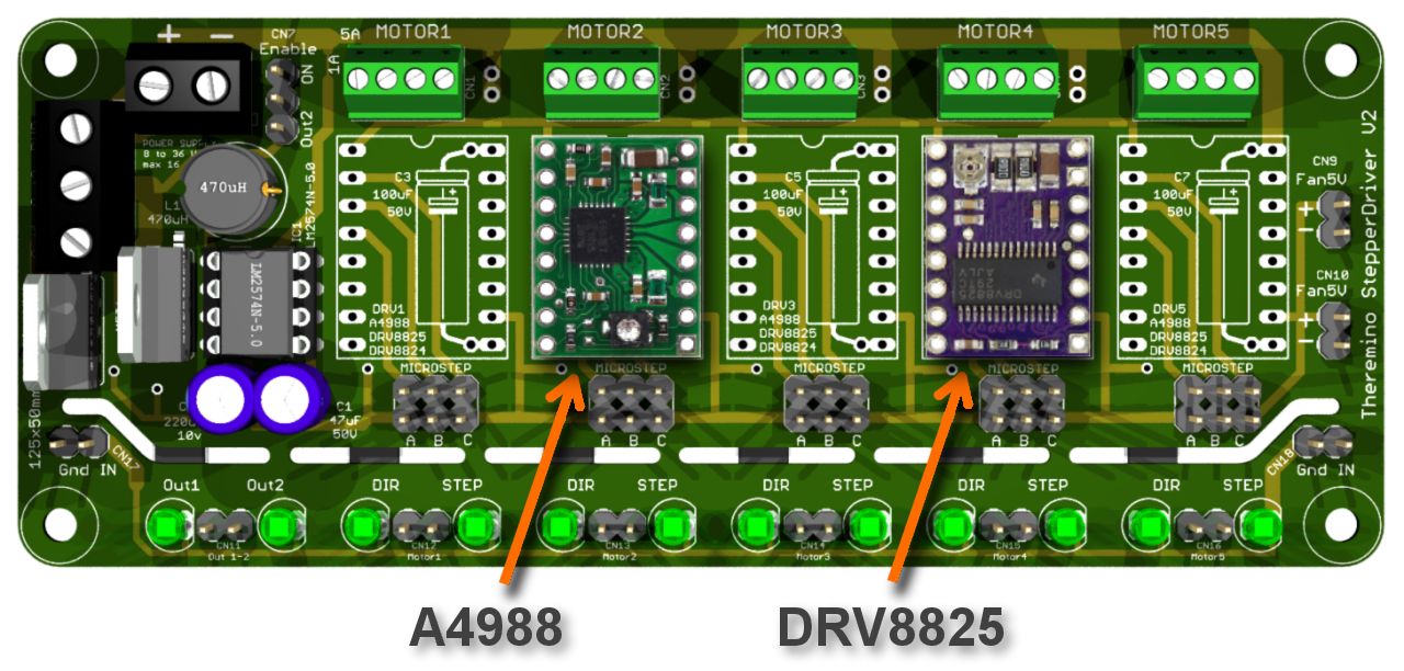
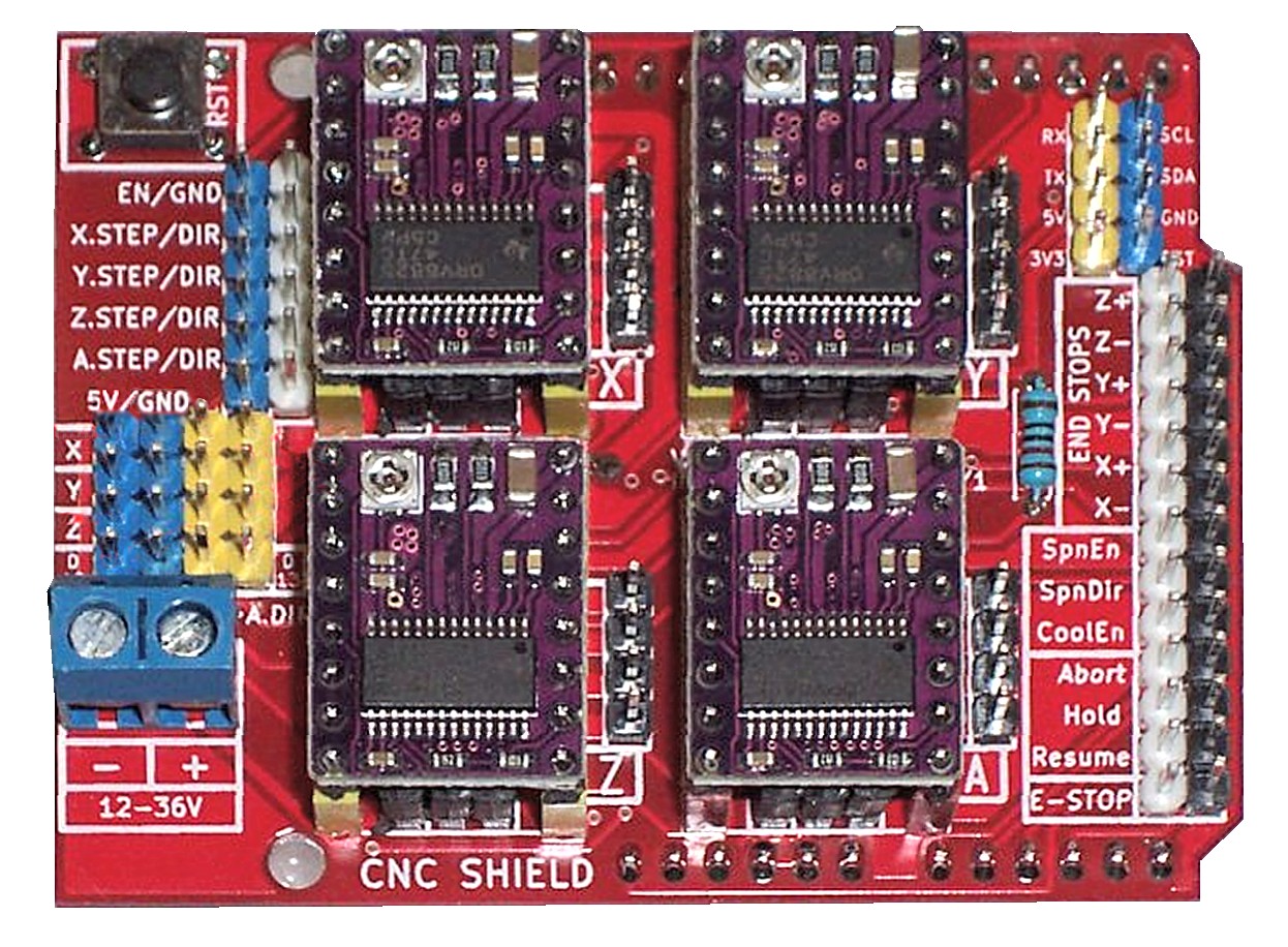
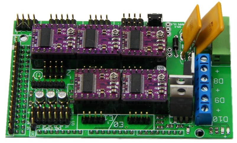
In the image above you see the plate Theremino_StepperDriver (information on this page), While in the two images below you can see the “Ramps” And the “CncShieldV3”. The latter cost less, but I'm not optocoupled, so they can generate electrical noise problems.


Recommend that you keep the maximum modularity, to allow future changes, improvements and replacements. Or with Breadboard and sideburns Dupont leads, or with the adapter plate Theremino_StepperDriver, or with the Ramps, or with a CncShieldV3 (the last two can be found on eBay).


Plates as the Ramps and the CncShieldV3, are not built specifically for the sistemaTheremino, to make the connections refer to the wiring diagrams. If in doubt please email us.
Posizionare i driver sulla CncShieldV3 e sulla Ramps
These images are only valid for the drivers DRV8825, sure that the A4988 must be inserted with the trimmer across. For other drivers check manufacturer's website.
A wiring example
ATTENTION: To enable the engines ENABLE signal must be connected to GND. So always put a jumper on “EN / GND”. If you forget to do this the search engines do not move.


In this picture you can see an example of wiring between Master and CncShieldV3.
In this wiring nine master Pin assignments are linked to four drivers and five InOut “of service”. The InOut can serve to control the ignition of the spindle motor and to read the bottom switch. Doesnít, still available three more InOut, on the Master.
Signal wires can be unplugged and moved at any time, even with everything turned on, but since there's a big, bad power supply connected to 220 Volts, you have to be very careful that the ground wire, between CncShield and Master, are shorts, strong and always connected.
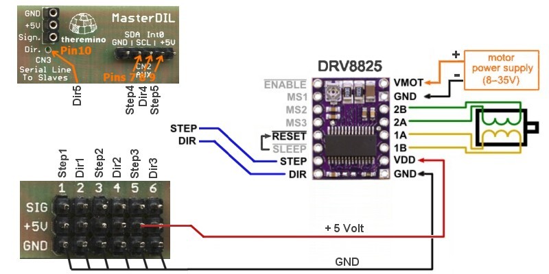
Connections between the Master and drivers Theremino
Here we explain how to connect directly the Master drivers, without using a Driver-Board.
Drivers A4988

Drivers DRV8825
Settings of microstep
| C (M0) (Ms1) |
B (M1) (MS2) |
A (M2) (Ms3) |
Microstep settings Drv8825 |
Microstep settings A4988 |
| Low | Low | Low | Full step | Full step |
| High | Low | Low | Half step | Half step |
| Low | High | Low | 1/4 step | 1/4 step |
| High | High | Low | 1/8 step | 1/8 step |
| Low | Low | High | 1/16 step | – |
| High | Low | High | 1/32 step | – |
| Low | High | High | 1/32 step | – |
| High | High | High | 1/32 step | 1/16 step |
Low means: “Connected to GND” i.e. “Unjumpered”
Alto means: “Connected to positive” i.e. “With bridge”
CncShield tabs and Ramps bridges lead to positive signals, so with all three jumpers removed you get “Full step”. Always use 8, 16 or 32 microstep, then insert the first two bridges or the last, or even all three. And remember to multiply, in HAL, the value “Steps for mm” for the number of micro-steps set.
ATTENTION: Some cards (Ramps 1.4 Some manufacturers), have the jumpers microstep selection not working. Some evil genius has altered the PCB to set them to fixed 16 microstep (why so serve in 3D printers). Just check with a tester selection jumper pins, If the pairs of pins are shorted, then it's one of these cards. In this case by removing the plastic bridges, with patience and with the Dremel, You can correct the PCB.
Adjust the trimmer to the current limiting
A4988 module, product to Pololu, The trimmer is from 10 Kohm and is connected to the 5 Volts with a resistor from 20 Kohm. Whereby the reference voltage, with the trimmer at maximum, is of 1.6 Volts. This reference is divided by eight internally on the chip and then compared with resistors 0.05 ohm resistor. Then you get a current equal to two and a half times the reference voltage.
On form DRV8825, produced by Pololu, The trimmer is from 10 Kohm and is connected to the 3.3 Volts stabilized. Whereby the reference voltage, with the trimmer at maximum, is of 3.3 Volts. This reference is divided by five inside the chip and then compared with resistors 0.1 ohm resistor. Then you get a current equal to twice the reference voltage.
The reference voltage is measured by a tester with the negative to GND and the positive on center of trimmer.
These are the current regulations that are obtained:
| Position of trimmers | A4988 | Drv8825 |
| At most | 4.0 Ampere | 6.6 Ampere |
| Three-fourths | 3.0 Ampere | 4.9 Ampere |
| A two-thirds | 2.7 Ampere | 4.4 Ampere |
| In mid- | 2.0 Ampere | 3.3 Ampere |
| In a third | 1.3 Ampere | 2.2 Ampere |
| In a quarter | 1.0 Ampere | 1.6 Ampere |
| Zero | 0 Ampere | 0 Ampere |
ATTENTION: As you can see, who designed these forms has completely missed the full scale. The maximum current bearable (even with the maximum of heatsinks and fans) is of 2 Amperes for 4988, and 2.2 Amperes for 8825.
The full scale of the trimmer is so two or three times greater than what would be reasonable. With a full scale so high the trimmer adjustment becomes two or three times harder. So be very careful to never go more than half (with the 4988) and never more than one-third (representing the 8825).
In addition, just to make the adjustment even harder, some trimmers have no mechanical background. You get to zero, the pass without noticing and you switch from ’ other side, giving the maximum current and immediately jump fuses and drivers.
SUPER ATTENTION: There are drivers with the trimmers that acts on the contrary. Whereby before trusting their drivers, It is good to measure the voltage trimmer. Adjusting to a minimum, counterclockwise, the tension should be minimal (from zero volts up to 100 millivolts). By adjusting the maximum, clockwise, the voltage should be maximum (from 1.5 to 3.3 Volts depending on the driver). If it doesn't take great care to use those drivers, always remember that act contrary (who made those PCBS should be transferred to the Department “sewer cleaning”, before he can do any more damage).
To adjust the trimmer you can proceed in one of three ways
METHOD 1 – SLOW: This method is suitable for precision lovers, wanting to know the numeric value of the current. Apply voltage to the drivers (even the 12 or 24 Volts that you need to feed internally on 5 Volts of some drivers) but do not connect the motors. Measure the voltage between ground and the metal part of the trimmer. Adjust the voltage to obtain a current that is half the rated current (= two and a half times the voltage, with 4988, or 2 times the voltage, with the 8825). Then begin to make tests up or down, always measured with meter for each test. Use a suitable screwdriver (better plastic) and be very careful. Of course for every test you should remove the power, disconnect and reconnect the power engines. Why this method is very slow.
METHOD 2 – FOR EXPERTS: Set the trimmers to eye, According to the current table. Then from one quarter and never go more than half (with the 4988) and never more than one-third (representing the 8825). To determine location make sure you where is the minimum (use lots of light and a good lens).
METHOD 3 – FOR EXPERTS: Mark the tip of the trimmer (opposite the flat spot), with a small sign of Sharpie. Procure a plastic screwdriver, lots of light and goggles. Turn the trimmer about a quarter, or less, before powering. Try the engine repeatedly, in order to get the maximum speed and power (If you increase the current increases the torque, but with too much current maximum speed decreases). Rises gradually the speed, until the engine shells and stops, then you try to move it several times and to amend the current to make it go better. With a little’ experience you can hear the sweet spot, listening to the sound of engines. The adjustments are done with micro-steps set permanently.
Who knows English well might also look this cute video of Pololu that explains how to adjust the trimmers.
Considerations that apply to all drivers
A single Theremino Master can control up to five stepper motors. The two wires red and black, that lead “+ 5 Volts” and “GND” the first driver, food can also be continued and other drivers.
Always connect, at least the wire GND, between the Master and the drivers. Also remember to connect “Reset” with “Sleep”.
ATTENTION: Always connect a capacitor to 100 UF between “VMOT” and “GND”. The electrolytic capacitor must be, Not type “Low ESR”, with the positive hooked up to “+”, It must be near the module driver (up a few centimeters). The operating voltage of the capacitor, must be at least 5 Volt more, motor power supply voltage.
In the absence of this capacitor, You can create extra hazardous voltages, that can cause you to lose the USB communication, damage the drivers and also damage the Master.
In this particular case, to avoid resonance phenomena produced by the high inductance present, do not use low resistance electrolytic capacitors in series (Low ESR), but the communes 100 uF, with approximately 1 ohm serial resistance. Read the warnings of Pololu on these pages:
https://www.pololu.com/docs/0J16/all
https://www.pololu.com/product/1182
Before powering everything must be connected reliably. If it comes off a wire motor, or link GND, A4988 driver becomes corrupted. If turning the trimmer does a short with the screwdriver, the driver instantly bursts. In some cases his chip explodes and sets off to smoke. The Theremino Master should withstand these tortures, but it's best not to put it to the test.
This is not to say, that the drivers are unreliable. If you do not make mistakes, never break.
However we recommend to always connect the drivers, with male and female connectors, for quick and easy replacement. We recommend that you buy five or ten, to get a little’ Commons, and bring down the price.
Drivers TB6600
On eBay you can buy drivers complete with photo-couplers and quite cheap. Are single driver, that is, you have to use one for each engine.
There are several models on the market, all with characteristics quite similar. On this page we describe only the TB6600, but the advice and patterns also apply to many other models, for example the TB6560 that you can buy on Store-ino.
In the next two images you see on TB6600, in version without container and container.
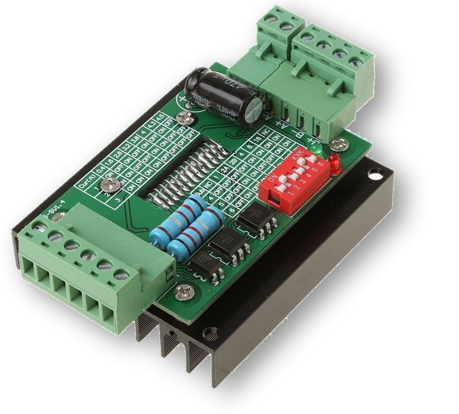
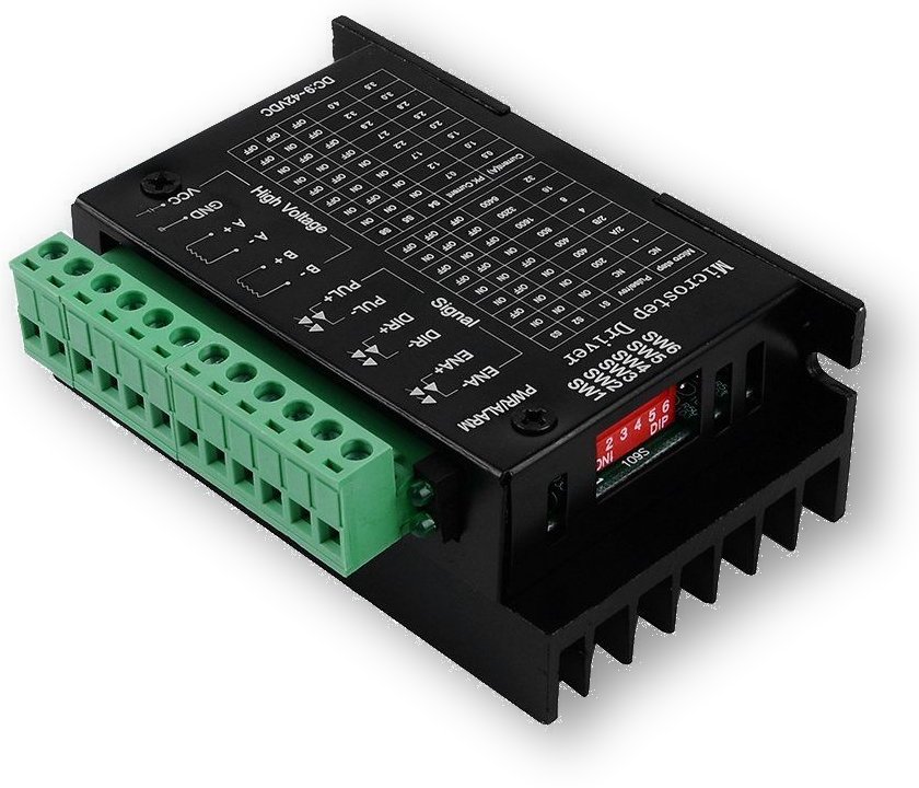
Characteristics of TB6600 driver
- Supply voltage from 9 to 42 volts
- Adjustable current up to 4 Ampere
- Internal temperature and overcurrent protection
- Regulation of micro-steps from 1 up to 32
- Photocoupled inputs with shared positive
- Positive inputs to connect to 5 volts
- The inputs must be driven with a transistor open collector
Links between the Master module and drivers TB6600
Internally TB6600 drivers (and the like), the photo-couplers are connected to positive via resistors 330 ohm resistor. Then to pilot them reliably, you have to use a positive voltage of 5 volts. The outputs of the Master module, that supply voltages between zero and 3.3 volts, cannot be linked directly to these drivers.
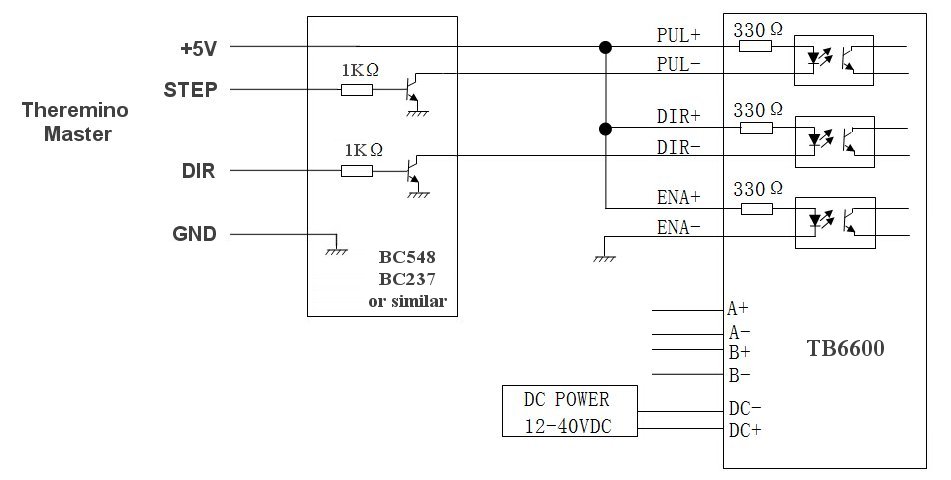
In addition, Since the photo-couplers are connected permanently to the positive, and pilot them from their negative input, It follows that one must drive them with an open-collector transistor. The transistor makes a signal inversion, why you get to light the photo-couplers when the output signal of the Master is high.
Some might better understand the following picture that is more realistic (thanks to Armando who sent).
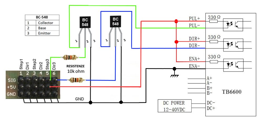
In the first image we used resistors 1k, that I am a little’ downs and wasted a few milliamperes. Since the current to be driven is low you can be raised up to 10k. In practice you can also use any intermediate resistor, for example 2.2k, 4.7k o 8.2k.
The two transistors and the two resistors, are open-collector type adapters. You can build on the wires connecting themselves as explained in This section, or on a printed circuit board by following This project.
Apparently these drivers may also work by connecting the outputs of Master K inputs- and PUL-, but the immunity to electrical noise would be scarce and the risk of losing steps would be very high.
Connect to the machines with the parallel port

Disconnect the ignition cable from the parallel, you connect it to Theremino CNC Adapter, and we start working right away. This adapter can be used for Mach3 or LinuxCNC (with the appropriate PlugIn), but better yet, with the application Theremino CNC, It is much easier to use.
https://www.theremino.com/hardware/adapters#cnc
Servo controls
There are all kinds of actuators and power. The servos are ideal for many applications, connect to any Pin of Theremino Master (up to 6 contemporaries) or to the pins on the slaves “Servant” that can fly up to 10 each. You choose “Servant” How to Pin type and work immediately. To try them, Click the appropriate column Value of application HAL, and move the mouse, holding down the left button.

The MG930 also marked TGY930, It has a positioning accuracy at least five times greater, compared to all other models. Being digital, It has a rather high starting current and a high pitched sound about 400 Hz. Its range is approximately 140 degrees.

The HX5010 is very powerful, less precise than the TGY930 but very cheap, costs only 4 euros and it's worth it all. Excursion = 200 degrees.

The HTX500 is very small, quite accurate and cheap, of course has a great power but it is enough for many small applications, He has one full 180 degrees and even some-more.


The HXT900 and the TG9e cost less than 2 Euro, they are good for all medium-sized applications and have one full 200 degrees.

The MG958 is a monster power 15 Kg/cm and only costs 11 Euro. Attention it consumes much current and you can't feed it with USB only. His trail: 135 degrees.
A servant very similar to this is the TGY-1501MG, He also from 15 Kg/cm, similar in size and more readily available. We haven't tried but the features are OK.
Summary of main features of servos.

These servos were chosen for the price, the accuracy and strength among a large number of models we've tested by buying them from: www.hobbyking.com (It has great prices and ships in a short time although it is located in the USA)
Another address for the servos is: www.robot-italy.com From robot Italy are not the models in this list, but only very expensive and strange versions, including those from three revolutions, eight revolutions and continuous movement. Always from Robot-Italy you can find sensors, motors, robotic grippers and many other interesting and unique accessories.
High-performance servos

–
–
–
This promises much higher performance DS8231 to TGY930, We tried but is produced by JR and you can trust.
http://www.jramericas.com/45190/JRPS8231/
Its features are:
Resolution Well 5900 steps on 120 degree rotation very low DeadBand (the Builder says "non-existent")
Two bearings spaced bearings for maximum accuracy Pulse rate control Loop from 250 MHz for high precision Current power consumption slightly higher than a normal servant Length     39.1 mm width     19.1 mm height       34.5 mm weight          49 grams Torque        1.26 Kg/cm Cost         70 Euros
Measure Step and Dead-band
Measure the accuracy of servo is easy, just put on the servo a display adapter and then insert a long rigid plastic tube 25 centimeters on one of the arms of the cross. Then crashes the servo with a clamp by turning it with the PIN at the top and with the tube parallel to the table that ends on a line graph paper, While a few millimeters above the row without touching it.
Finally moves the servant of very small quantities with the up and down arrows and can be counted on line how many small movements are seen doing for every millimeter, These are the “Step”
To measure the dead-band going first one way and then it begins to turn back with the up and down arrows until you see it start to go back, the number of times you pressed the arrow, with a simple calculation, indicates the width of the Dead-band.
Unlimited rotation and torque servo with variable

Normally the servos have a rotation of approximately 180 degrees, but for some applications would be preferable unlimited rotation engines. Normally in these cases using stepper motors, but they have disadvantages.
Steppers require a complex driver circuit, require acceleration and deceleration ramps and have very little torque. With steppers if you accelerate too fast, or exceeds critical torque and speed, you lose distance and then you lose the alignment between software and hardware.
To overcome the limitations of stepper, most expensive cars use motors in continuous, with feedback loops and external to the motor position sensors. With a servant amended we get exactly that, but without the bridge driving circuit, normally required for engines continues. Bridge driver already exists on the small servo chip the feedback mechanisms will add them, with sensors (optical or magnetic) and software. In the most difficult cases, Thanks to the power of the PC software, you could also add a PID algorithm.
With a simple change can change the servo to make them work in multiturn. In the unmodified servant, the control signal controls the position of the crankshaft. After changing, the signal controls the speed and torque, in the two rotation.
Here's how you get from the servant multiturn, connected to a PIN configured as Servo_16.
| Signal | Strength and speed |
| 1000 | Maximum force and maximum speed clockwise |
| 750 | Half strength and speed clockwise |
| 600 | Minimum force and speed clockwise |
| 500 | The servant stands still |
| 400 | Minimum force and speed counterclockwise |
| 250 | Half strength and speed counterclockwise |
| 0 | Maximum force and maximum speed counterclockwise |
All servos are editable for multi-round operation, but we have prepared the patterns only for HXT900. These servo have many advantages, consume little power, can be powered by USB and only cost two euros from HobbyKing: HobbyKing.com _ HXT900 (When you order from HobbyKing do get some stacks of 10 extension leads: from 30 cm and from 60 cm)
With the servo HXT900 the rotation speed is adjustable, from a few rounds per minute to about 80 RPM, and the torque is adjustable from a minimum (stops as soon as you make a little effort) up to 1.6 Kg/cm (You can't stop the PIN, tighten it with your fingers).
The following table shows strength and speed that can be obtained from a HXT900, transforming the rotation in a linear movement with threaded rods or pulleys.
| Method |
Mm per revolution |
Speed maximum (mm/min) |
Strength maximum (Kg) |
| Threaded bar 1 mm/Rev | 1 | 80 | 60 |
| Threaded bar 2 mm/Rev | 2 | 160 | 30 |
| Threaded bar 4 mm/Rev | 4 | 240 | 15 |
| Pulley diameter 3.2 mm | 10 | 800 | 6 |
| Pulley diameter 5 mm | 15 | 1200 | 4 |
| Pulley diameter 10 mm | 30 | 2400 | 2 |
| Pulley diameter 20 mm | 60 | 4800 | 1 |
The characteristics of HXT900 indicate 1.6 Kg/cm. Then a HXT900, pulley 20 mm in diameter, could raise 1.6 Kg. In this table, to be on the safe side, We calculated 1 Kg.
Modify a servo HXT900


Remove the adhesive labels on both sides, unscrew the four screws, Open the servo and cut the three red wires, close to the circuit board.


Pull the engine bolt, parading the potentiometer from its headquarters. Cut with the Clippers the metal tabs, where are soldered the wires.


Remove the two gears from the shaft and do away with the Clippers all internal parts, that prevent rotation. Check that the shaft turns freely.


Cut with the Clippers two teeth lying on the larger chainring.
Thread the potentiometer in place roundabout. Slip the gears on the pins, starting from the smallest. All gears go with big bottom, towards the engine. The large chainring, that brings the engine bolt, should not be pressed too, but only to get closer to the other gears, without touching them.


The left image is a schematic and functional, the one on the right indicates modifications to do and where to put the resistors.
Add two or three small SMD resistors (0603), as specified (click on images to enlarge them)
There is also a HXT 900 with circuit different from that shown here. In this file there are the schemes and all the information we could find. Unfortunately the datasheet is in Chinese: uploads/files/HXT900_Type2.zip
Finally close the engine and try out.
Edit servo other than HXT900
It is impossible to provide instructions for all kinds of existing servo. In this file there are all information, the schemas and data sheet, We've collected so far: uploads/files/ServoInfoAndDatasheets.zip
Multi-round commercial servant
Finally, manufacturers have discovered this possibility. The catalogue Pololu already exist four models, with prices from 5 Euro up to 15 Euro. The link below shows the smallest, but from this link, and explore the entire catalogue Pololu, and not only for engines:
http://www.pololu.com/product/2820
Principles of operation of the normal servo and multiturn
Each model of servant differs mechanically and electrically, but the principles are the same for all servo: uploads/files/ServoCircuitsAndTimings.zip
Operation of standard servo.
- The signal from 0.5 to 2.5 mS, is converted into the servo chip, in a value that ranges from 0 at three volts.
- The small potentiometer inside the servo (Depending on how it's turned), It also provides him a value from 0 to 3 Volts .
- If the two voltages are equal, the chip voltage to the engine not.
- As the two voltages, deviate from each other, the chip by more and more power to the motor.
- The voltage to the motor is given in a way, or in the opposite direction, Depending on whether higher voltage or the other.
Multi-round operation of the servo.
- The potentiometer is replaced with two fixed resistors, simulating the potentiometer always in the middle of his race.
- Everything else is exactly as in the normal servo.
- If the command signal is half (1.5 mS), then the two voltages are equivalent and the chip does not supply power to the motor.
- As the two voltages, deviate from each other, the chip by more and more power to the motor, one way or the other.
How much power sent to engine?
- The chip inside the servant acts as a "reaction component".
- The reaction occurs in closed loop servo for "normal" or "feedback".
- In multi-round servant it is a simple reaction or "lug".
- In both cases there is a reaction curve.
- Response curve, Depending on the control signal (deviation between the two voltages), determines the voltage to the motor.
- Response curve is a kind of "S" with a flat spot in the Center.
- The slope of the curve (reaction force) is regulated by a resistor.
- The flat spot in Center (dead zone) is adjusted using a second resistor, that determines its width.
- Theoretically it would be better to have a lot of reaction and short dead zone, but you can't exaggerate.
- If you exaggerate the reaction parameters, the engine is more firm and can even get to swing violently.

Brushless servomotors


There are motors with or without brushes, of all kinds, starting from a few grams of weight up to about 10 KW power
In the catalogue: www.hobbyking.com you can find motors with great prices and controller to pilot them with currents up to 300 amps with standard signals of the system Theremino.
With each “Slave” of type “Servant” You can control up to ten independent motors.
The pictures show a 6 Kilowatt (125 Ampere in 48 Volts) and a small controller for brushless motors.
Some of the most interesting examples of selected engines
The catalog HobbyKing has changed. We had selected engines have changed links and this for us is a problem because if we publish broken-links job seekers we penalize.
Moreover the catalog HobbyKing has become harder to see, Why can't I order engines for power. So the best we can do is point out the first page of the motors Outrunner, sorted by size:
https://hobbyking.com/en_us/electric-motors-1/size.html
Examples of controllers for engines
Controller from 6 Amp. for brushless motors (BRUSHLESS) – about 6 Eurohttp://www.hobbyking.com/hobbyking/store/__4318__TURNIGY_Plush_6A_8bec_6g_Speed_Controller.html
Controller from 25 Amp. for brushless motors (BRUSHLESS) – about 8 Euro
http://www.hobbyking.com/hobbyking/store/__11616__Turnigy_AE_25A_Brushless_ESC.html
Controller from 20 Amps for motors with brushes (BRUSHED) – about 3 Euro
http://www.hobbyking.com/hobbyking/store/__9090__Turnigy_20A_BRUSHED_ESC.html
Controller from 30 Amps for motors with brushes (BRUSHED) – about 6 Euro
http://www.hobbyking.com/hobbyking/store/__6468__Turnigy_30A_BRUSHED_ESC.html
Motors in the catalogue Pololu
It is recommended to start with this link, and explore the entire catalogue Pololu, and not only for engines. From Pololu everything for DIY.
http://www.pololu.com/category/22/motors-and-gearboxes
Motors in the catalogue Solarbotics
Also here are motors (and other useful components to Makers). Cost more, but it's worth a look every now and then, even in this catalog:
https://solarbotics.com/product/gm2/
https://solarbotics.com/catalog/motors-servos/gear-motors/
ATTENTION: Links to commercial firms might suggest a hidden advertising, for that you should specify it: Nobody is paying off and we never exchanged a single email with any of the companies listed here. So we are free to talk about good and evil than anyone and our “shopping tips”, they are just useful information, obtained during our research of components.
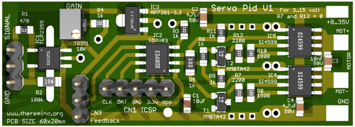
ServoPID
This module is an H-bridge which can control DC motors up to fifty watts (until a few amps and over thirty volts) and turn them into the servo motors.
We thank the manufacturer and seller of eBay MaxTheremino, which has readily prepared printed circuit boards and kits for this project. Follow of MaxTheremino link on eBay and if he had them still write him catalog to have them sent.
Those who prefer to buy only the components and print the PCB techniques DIY, It will be located in compressed file all the files needed to build this module.
Circuit boards in Eagle format, images, simulations LTSpice and schemes:
ServoPID_V1.zip
The control signal may be a classic signal “Servant” or “PWM”, that can come from a module Master, by one IotModule, from a Netmodule, or even from a remote control for model airplanes.
The H-bridge is controlled by a micro-controller PIC, Programmable with the firmware that we have prepared for various needs. In the simplest case you are running a motor forward or backward, adjusting the speed. In more elaborate cases using a potentiometer to measure the position and adjusts the position with a PID algorithm.
With the potentiometer and the PID it has the same operation of the classics “Servant” but, Unlike commercial Servant, you have the possibility to vary each parameter, Morta area, measurement resolution of the ADC and the PID coefficients.
Unlike normal servo input signal is isolated with an opto-coupler. This allows to keep totally separate the mass of the motor power supply circuit from that of the control PC. This will radically eliminate electrical interference that could cause malfunctions.
WIRING
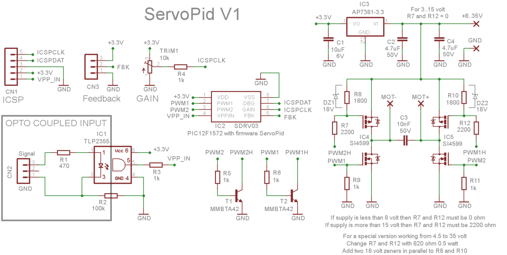
The control signal, Servo type or Pwm, It is connected to the connector CN2, through R1 which limits the current to a few milliamperes and pilot the LED of the photo-coupler.
The amplitude of the control signal must be from 3 to 6 Volts, the positive pulse time must be between 500 to 2500 uS (about), and the repetition rate from 50 Hz to 500 Hz.
The control signal continues through the photo-coupler IC1, through R3 and arrives to pin 4 of the micro, which measures the time with high resolution (thirty-seconds of microsecond).
The connector “ICSP” It is used to program the PIC with the control firmware and also to connect a USB serial converter for debugging. See the next section “FIRMWARE”.
If you configure the firmware using the PID, then the connector “Feedback” It must be connected to a position measuring potentiometer. Usually this potentiometer is rigidly coupled to the output shaft, which is moved by the drive shaft by means of a reduction gear or belt. The feedback potentiometer can also be multiturn and must be a linear potentiometer, with values normally between 1 k ohm and 10 k ohm. The central of the potentiometer must be connected to the central connector, the wire in the diagram has the name FBK.
In the case that the feedback takes place on the contrary, you can swap the two side connections of the potentiometer between them. But be careful that the center must always be connected to FBK. If you fail the potentiometer could be heated and damaged.
it trimmer “GAIN”, It serves to manually adjust the gain of the PID, it uses only with some firmware configurations and mainly during the tests of a new engine, to fine-tune the PID values. The resistor R4 decouples the trimmer from ICSPCLK signal, so you can use the ICSPCLK signal for debugging with serial.
The voltage regulator “IC3” creates a voltage of 3.3 Volt very stable. This voltage feeds the micro-controller, potentiometer feedback, Qtr1 the trimmer and the optocoupler IC1.
The two output signals of the PIC, with name and PWM1 PWM2, Fly bridge formed by the four MOSFET contained in the chip SI4599. The bridge is closed with a PWM signal high frequency (normally 16 or 32 KHz), which regulates the engine speed and makes it rotate in one direction or another. During the commutations the PIC ensures that the two branches of the bridge are never closed simultaneously (which would short-circuit the power supply).
The supply voltage must be adapted to the engine, if it is too much the motor may burn. If you do not make changes to the schema can be used to supply voltages from 8 to 35 Volts. The diagram shows the modifications to be done to allow other two power supply range. The first range (from 3 to 15 Volts) It requires only to short R7 and R12. The second range (from 4.5 to 35 Volts) It requires replacing R7 and R12 and also to add two Zener diodes 18 Volts.
FIRMWARE
At the ICSP connector connecting a programmer PicKit2 (see This page). Note that the file PK2DeviceFile.dat, which also includes the PIC12F1572 used in this project, It is only valid for PicKit2. So most likely with PicKit3 not be able to program this PIC (or at least we do not know how to show you).
In the ZIP you download at the end of this section you will find the file ServoPid35.hex already completed and ready to be written in the PIC with PicKit2.
This file is the simplest version control. By varying the control signal from minimum to maximum moves the variable speed motor in the two directions. With the control signal in a central position, the motor stops.
SENDING DEBUG DATA FROM THE SERIAL FIRMWARE
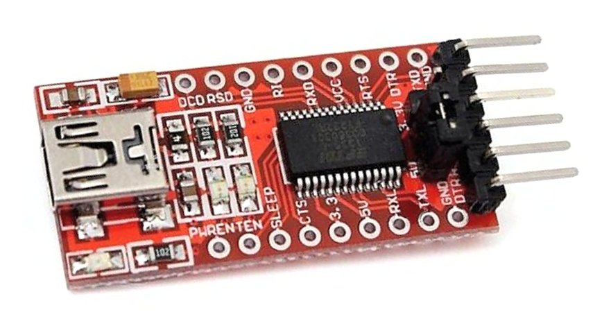
The wire ICSPCLK the ICSP connector is also used to send debug data from the firmware to the serial line. To use it you have to connect GND and ICSPCLK to GND and RX pin of a Serial-USB converter such as what is seen in this image.
Then you change the firmware to send values to the serial debug, receiving data with the application Terminal and optionally displaying them with the SignalScope or other applications of our system.
EDIT AND RECOMPILE THE FIRMWARE
To modify the operating parameters and implement the most complex version control (position control with feedback and PID) you must edit the file ServoPid35.bas and recompiling. The compilation creates a file HEX which it can be written in the PIC with PicKit2.
To edit the file we recommend using the excellent FineLineIDE and to compile the ProtonCompiler.
Both they are free and you can download them from the following links:
www.protonbasic.co.uk/content.php/2077-FineLineIDE
www.protonbasic.co.uk/vbdownloads
The instructions and helpful comments to modify the firmware can be found in the file ServoPid35.bas and at the end of the file you will find a glossary of terms used and step by step instructions to adjust the PID parameters.
Mind you this is a complex firmware and it will not be easy to learn and use in an appropriate manner all its options. The hardest part is definitely adjust the PID parameters in order to avoid oscillation and at the same time get a prompt response and smaller die area can.
We did our best to facilitate the adjustment of the PID parameters, using the Ziegler-Nichols method and simplifying it further. We also corrected some errors of the method Ziegler-Nichols published on Wikipedia, but the setting of the parameters for a new system (engine, reductions and feedback), It remains an operation by specialists.
Notes for the firmware
To decrease the dissipation on the MOSFETs it is advisable to set a lower frequency for the PWM in the firmware. Normally the frequency is set to 20 KHz but in some applications we have lowered it to 2 KHz reducing the heating problem of the MOSFETs to practically zero.
The only contraindication is the noise which will increase a little. So try to lower the PWM frequency and then check with your motor if the noise increase is tolerable.
DOWNLOAD FILES FIRMWARE
In the following you find ZIP files:
– ServoPid35.hex ready to program the PIC in simple version open loop.
– ServoPid35.bas to edit and recompile with FineLine IDE
ServoPid_Firmware.zip