
Recommendations for CNC machines
If you need advice on search engines to use, mechanical components or how to assemble them and buy them, Please contact Fabio di Arezzo which in recent years has gathered a lot of experience on CNC milling and engraving machines with lasers.
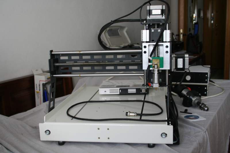
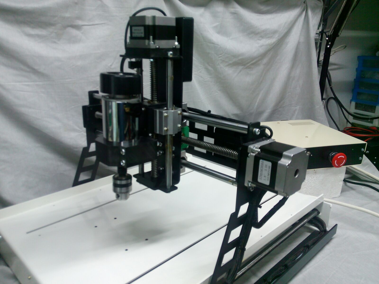
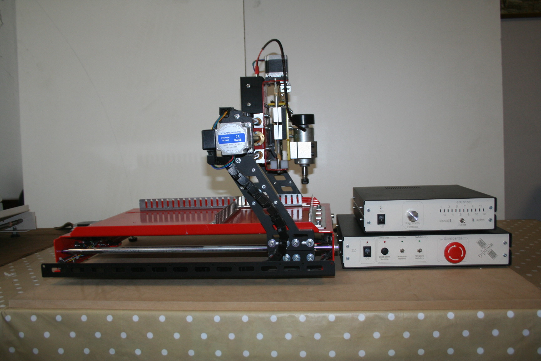
In upcoming pictures you can see some of his achievements. Clicking the images get bigger and you may notice that are combined machines, that is, that you can mount either a laser that a cutter.

Write to Fabio for recommendations, to buy together components or to make you procure from him of the kits of components. Or you might even agree to build parts or complete machines.
Fabio di Arezzo – Civitella in Val di Chiana (AR) – fabio.cve31@gmail.com
I add here some new images that he sent us in the 2024 and also a PDF manual
Radar and robotic arms

This is the first sonar das Riboni, l ’ application ThereminoRadar was born from this prototype. We thank Mauro, for keeping us involved and for insisting, up to get it to work.
Download ThereminoRadar here: /downloads/automation * radar and information on sensors here: /hardware/inputs/sensors # usound
– – – – – – –

Mauro Radan is also experimenting with different versions of parallel grippers. His mechanics are designed very well. This is a version with high power servo. These servos are not suitable to write because of their dead band, but are great for catching and lifting objects. The two servo at the base and the very robust construction, heavy enough to lift objects.
– – – – – – –

One of the first prototypes of ThereminoArm. This version was still a Master and a Slave, because the first Master did not have configurable PIN. Now you do everything with just Master and advance even two pins. The April update 2017: the new firmware of the Master, increases the number of pins to 6 to 12, so now they advance eight pins for general purposes. Also new firmware may also drive the stepper motors.
You can then build very precise robot arms using small stepper motors and belts. I recommend using a very high reduction ratio, at least five but better if you manage to get to ten. In this way the 200 steps per revolution will become 2000 steps per revolution and you can get an accuracy of 0.7 mm with half-meter long arms. Accuracy that will increase to about one-tenth of mm and above using the microstep.
– – – – – – –
A Robot is not necessarily an articulated arm. With a little’ fancy, You can compose simple and efficient machines.

A robot “instructional” built by students of the Institute ’, C. of Corniglio
The Institute's proposal, motivation i.c. Corniglio is: “…join the digital world with the real world and concrete” and that's precisely why is born on system Theremino. A warm thanks for your research!
Sketch and Firmware
Many after learning the language Arduino sketch, they wrote that they would like to use it, for Theremino. Unfortunately the language sketch was thought, only dell processors ’ Arduino and transplanting it on other “micro”, would become so different, to lose any possibility, Exchange programs between the two.
Our PIC programming in C or C++, using an IDE standard and standard compilers, We use GNU Compiler, It is Open Source.
As far as the huge popularity of Arduino, It can make us look “several”, in fact quite the opposite is true, is Arduino using a nonstandard language, made especially for Arduino and valid only for Arduino.
Sketches are not true firmware programming, but a simple programming, that hides all the “outline”. With the sketch, l ’ efficiency is the ability to maneuver, are limited.
In addition to a didactic deformation sketches, you learn to use an abstraction of micro, instead of the micro itself. To learn how to use a micro, You should consider the data sheet of the manufacturer, not the instructions of Arduino.
That being said, Luckily, the system firmware Theremino, requires no programming. We are in 20xx and supposedly the InOut a PC, as well as the firmware of a mobile phone, or a washing machine, are working. “How are”, without having to re-schedule every time, Depending on whether you want to wash shirts, or blue jeans.
Shift of perspective
The shift of perspective, between Arduino and Theremino is in fact, move the ’ intelligence from the firmware to the software. This shift multiplies per thousand the available speed, the computing power, the memory, and the ease of programming.
For this approach, You must be permanently connected to a PC (or a NetBook, a eeeBox, a Tablet, an embedded PC or a Raspberry Pi, as explained here: blog/standalone-applications#standalone, and also here: downloads/notes-on-software # computers)
Many devices, like printers, monitors and mice, they are constantly connected to the PC and all they find “normal”. Yet many people think that a “device”, such as a robotic arm, or a 3D printer, should be autonomous, and probably a pile…
Robotic arms and intelligence
We do l ’ example, watch case, a “robotic arm”. Many manufacturers of robotic arms Arduinici, they realized that their arm “battery powered standalone”, in the end he always does the same thing. What he's missing? Communication and software, powerful algorithms that keep in touch 3D data, with the outside world, sensors, Webcams, microphones, understand the GCode, and communicate with other applications, in real time.
Micro are not designed to handle 3D files, or decode audio signals, do not have adequate power, to play midi files, or decode the video of a WebCam. And even if they are forced to do so, the hurt. Said with other words: “The appropriate place for the brain, It's not close to the muscles”
Another reason, that makes it very smart, connect firmly the arms and 3D printers to your PC, is that you have to supply them power. When you exceed the phase toy, power needs, become too heavy, for batteries.
How are the professional robotic arms ?
- Have big cables, that carry power and data.
- Communicate constantly with a hub PC.
- Contain only the firmware, intelligent algorithms, they're all on PC.

Click on the image, for a better look.
Which language to use?
Once you have decided to move the ’ intelligence, from the firmware to a high-level language, which is the best language to learn?
Here is a matter of taste, Some say that only exists on C++, and treat with contempt, every other language.
Other, like us, think that C++ is a language older, that requires much more time and energy, recent languages. And they also think that C++ and similar (C, Java and all languages with the semicolon to each row) formal languages are poorly structured and poorly, that invite you to write, so “dirty” and confused. In these languages, you can write, things acceptable by the compiler, but absolutely unreadable, for humans.
We prefer more structured languages, that help to write well, and to minimize errors. This process of gradual estrangement, from machine language, is underway for fifty ’ years and with each new step, c ’ is anyone who complains and complains about the old languages. But the process will continue, and eventually we'll get to program, in human language. Currently the human language is VbNet.
As the modern languages (VBNET and C #), they have a power and impressive speed, because their basic functions, are not rewritten every time from scratch, but are instead ready in “Runtime” and written with optimized algorithms, and adapted to the operating system.
A second advantage of modern languages, is to be independent of the operating system. An application written in C # or Visual Basic, runs without changing a comma even on Mac, Linux and Unix. (This in theory… in practice only on Windows works fine, While on other operating systems, implementations are incomplete and full of errors)
In conclusion we We suggest using VbNet or C # (very similar to each other) Almost all applications, of the Theremino System, are written in VbNet, because we find it more “Human”, but you can easily switch from one language all ’ more, using SharpDevelop to translate.
To install the developer tools, Read here: downloads/notes-on-software # instruments
Hello livio , I fitted a new electro spindle to my self-destructive cnc with its small reverses that has n a pwm signal with the following characteristics: 3, interface Terminal MACH3 supports PWM speed control signal outside entrance, external PWM input requirements: level 3.5-12V VPP, frequency 1 k-10 kHz, spindle speed control suitable for MACH3, (Note you need to disconnect the external control signal PWM XH2 potentiometer Thorn. 54-3 p is effective or cannot be controlled).
I tried to configure by the book's legs 11 E12 but I can't get it to work automatically . from the hall I don't know what kind of leg I enter, If kindly you can
Aid to the various operations by writing configuration specifically ka x. Thanks Joseph
Inverter has two legs and the other one that says pwm gnd
You have to connect both GND that SIGNAL
The Pin you use to get the signal goes configured as FastPwm
The frequency of FastPwm should be set from 1 KHz to 10 KHz (set it to 2 KHz)
Then you have to press the button “Duty cycle from Slot”
And you have to set the right Slot.
If you can't write me at engineering at sign theremino dot com and we'll hear over the phone.
Hello
Livio
Friend can help me get that signal as my driver works 2kHz to 20 to control the spindle of mach 3.
The frequency set it to 2 khz
To read the rest of the HAL application instructions and CNC.
If friend thanks for answering what happens is this I have a little old driver is called (CNC INTERFACE BOARD ST-V3)that does not come with pwm output 0 to 10 only volt relay connector u v w of the inverter Spindle therefore momentarily to solve this mishap and control my spindle perform a circuit with a 555 and a bridge where the bridge h h works 2kiloherz to 20kilohez for maximum velocidad.Lo interests me now is to send that signal not by the 555 Potentiometer but send me the Mach3 or know that pins are used to receive that signal I hope you can guide me thanks.
Difficult to understand…
The CNC application you are using is Mach3 ?
In this case the signals will come from the parallel port of the PC and which use PIN is written in the Mach3 manual.
We do not use Mach3 help and do not know the details.
Good evening, my name is Joseph's for a while now I dabble with a little homemade cnc. I wanted to tell my experience regarding the theremino master and its software theremino cnc.
Before entering the world of theremino I flew my cnc with Arduino and its respective grbl controller software, cool see it working, the problem arose when I had to pause the job, adjust some parameters of adjustment for the x axes, y, z, to restart the piece from a point at my own pace, all this was not possible and therefore I trust to luck that work so well, but I happened to redo the same work more than once, not being able to fix the car in progress…
Finally with the discovery of theremino I fixed what wasn't possible with Arduino, now read work machine with theremino, as well as being a cool, is a safety at work don't make a second time. Theremino CNC is a terrific control software, There is nothing that you can't do, by adjusting the parameters of the respective axes, the spindle speed, at the start of the tool from a particular point and much more… and the most important thing was the availability to configure the right parameters with the staff of theremino, that gave availability via telephone x a number of adjustments concerning the loss of distance, caused by grounding and other, Another thanks for your work.
Hello Livio, Finally in a few days I will have the aluminum panels for mounting permanently the CNC.
I could use some advice, prior to the final Assembly, to verify exactly what creates a progressive loss of steps in Z.
A question: But a G-code can affect the performance and accuracy of a CNC?
Wonder why the defect occurs even when cutting the air.
I add… to test I used Automation by creating a small loop to generate movement on the three axes to finish to take a measurement of the Z axis on the micrometer and start again. After a course of 40 minutes all in fast motion, (I don't know how many dozens of measurements carried out but I think 70 or more) the second hand of the micrometer was always in the same position.
I think even if now there are big mistakes is CNC wood mechanics, but gradually losing in Z seems strange.
However short, don't, don't run and again the correct wiring.
Thanks and see you soon.
Vincenzo
Did you use Theremino Automation always with Master outputs are configured with the true Steppers?
If you did so and there was loss of distance then STEP and DIR signals and the Driver does not have problems. Nor ThereminoCNC can have, because he passes from the slots and if the Slot is at zero, the tip should be where it was at the beginning.
Your only option is a loss of distance due to too much speed and/or acceleration but still closer to vibrations. Increases micro-steps to decrease vibration and, If possible, interponi a toothed rubber belt, to uncouple the motor from the crowd that he controls.
And of course do many tests until you figure out what it is.
Yes, with the configuration as stepper.
I'll try to increase the micro-steps to 1/8 to see the trend.
to 1/4 is a little jerky. In XY is impressive precision. I split the penny.
See you soon.. Thank you.
just getting ready to publish photos and videos.
Hello,
I recently discovered the system Theremino
and I am venturing to build my first CNC.
I need a manual axis with a magnetic or optical line
to control its position.
You can link it to Theremino?
If you can, You can also store the coordinates of a given point?
Theremino CNC is a simple application. You can only do what he does. And what this does is all written in the instruction file.
I suggest you watch this page carefully in-out slots that are a little’ an index of all you can do.
Does not work Theremino CNC with new functions otherwise eventually becomes a mess like other similar apps that no one can use.
If that's not enough that you must pass to Mach3 CNC Theremino and…. best wishes.
I switched on the CNC and everything is ok.
I just can't move without gcode.
For example: to go and tap manually a wall already milled,What do I press?
CTRL + arrows moves but 0.01 at a time
There is a button that does’ move your CNC until is pressed?
If you use the arrows by themselves move with speed “Jog speed normal”
If you use the arrows + SHIFT move speed “Jog speed with SHIFT”
If you use the arrows + CTRL single step move by a tenth of a millimetre.
The rates set in the menu “Options”. The settings range from 1 to 100 and are percentages of speed “Rapid” that, ATTENTION, should never be greater than the MaxSpeed setting in application HAL.
In all cases you must first click in the window where you see the processing to enable the movements with keyboard.
Hello Livio, I have a CNC controlled by Theremino CNC machining fine,
You can make perfect recordings, I would like to improve the depth control Z axis to compensate for uneven floors he plans and PCB,
I discovered that there is a program called “Term autoleveller” that probe the surface of the PCB and calculates the difference of flatness correcting automatically the depth of engraving, to do this requires storing values of the Z axis of the various PCB poll points than the program itself runs ,now the question you ask is: would it be possible to store these values with Theremino CNC by extracting them or storing them on a file margari ?
I thank you in advance and congratulations for the great work of Theremino.
Franco
No, It's not possible.
Theremino CNC is a simple application and will be simple.
If we start to complicate it becomes a draft of Mach3 and LinuxCNC, that hardly anyone can use.
Great Post.This blog contains really interesting stuff on robotics and CNC Machines. Very interesting article. I learned a lot .Very easy to understand. Thank you for sharing this article.
Good morning to all and congratulations for your project.
Long ago I had assembled a three-axis CNC machine (handmade Cabinet) piloted by a card-controlled Chinese Mach3 but I had great satisfaction. I then decided to upgrade all at Theremino.
I purchased the MasterDIL V4, the drivers DRV8825 and, as suggested in the Hardware section, a CncShieldV3.
I ask you, not having found, a description of connections to make between the MasterDIL and the Driver Board for driving correctly the three drivers without risking to send them up in smoke.
Thanks in advance and congratulations for your project
Antonio
The links between Master and DriverBoard are simple:
– GND GND Master of the driver board
– 5V to 5 v Master of the driver board
– SIGNAL of the Master in DIR or STEP of the driver board
However, the links between the MasterDIL and the Driver Board hardly “they send in smoke”. The danger is all the side motors, adjusting trimmer, feeder… there don't have to miss anything. And attention that the CNC Shield must also be enabled.
Read all suggestions on this page, You'll find pictures in good resolution of CncShield that may help for links.
https://www.theremino.com/hardware/outputs/motors
Thanks for the advice.
If I have doubts and if not much trouble to ask you again some advice.
Thanks again.
Hello Livio, the problem for which I require courteous help is on the way to connect a spindle of a small CNC2018 the control electronics that consists of a Master unit and Theremino StepperDriver and, Consequently, How should I configure my software Hal and Theremino CNC.
The spindle ELEMANDER11 comes with own transformer equipped with diode bridge and with these specs:
Electric spindle:
– Power supply: from 12 VDC at 48 VDC
– Rotation speed (revolutions per minute): 12 VDC – 3.000 / 24 VDC – 6.000 / 36 VDC – 9.000 / 48 VDC – 12.000
– Power: 300 Watts
– Couple: 230 N·m
– Insulation resistance: > 2 Mohm
– Dielectric strength: 400 volts
Transformer 50 VA:
– entrance: 220 VAC
– exit: 36 VAC
Diode bridge:
– 1.000 V – 10 A
In the documentation I couldn't find anything about it, I could probably have been too hasty, but from what I can understand from the characteristics of the StepperDriver should not be possible to do without a relay to control the electro-spindle.
I apologize for the possible naivete of what has been said but little time has elapsed since I started “Chew” CNC and electronics.
Thanks Livio for the time you want to devote to my request and compliments for the passion that all of you Theremino put in the many projects developed, never pull out the comparison and the support of those who resort to your assistance.
Fabrizio
You could use a mechanical relay or a Optotriacs, the mechanical relay will work for sure without problems but may have a shorter life span (never mind cost little and after years I replace). The phototriac isolation is gentler and is not guaranteed to work well with the feeder spindle. Then the test would require a first phase optotriacs and tuning, but when in operation would last forever.
Here you will find the explanations to drive a mechanical relay
https://www.theremino.com/hardware/outputs/actuators#simplereledriver
Here you will find optotriacs's artistpage
https://www.theremino.com/hardware/outputs/actuators#optotriac
If you want to use the write me optotriacs and I will have to explain how to make the first tests.
I would now like to do, But if you are not clear write me.
The problem is that if the power supply is too crazy and not inductive triac could do open and close the circuit. And if the Triac were to close a single half-wave for a long time, could heat the spindle power supply transformer.
In addition, there is a damping network optotriacs (R5 and C3) He does spend some’ of current even when the Triac is open. This may prevent weak load turns off (such as low power led lamps).
To verify that everything is in place you should then put a meter in parallel and check on the power to the power supply is 220..230 volts AC. And that when off is very low, Let's say less than 10 volts AC. These tests are done with the AC adapter plugged in and turned on. And are done for a short time, maximum seconds, to avoid heating the transformer in case there was a single half-wave.
– – – – – –
The Pin-out of the Master you have to set it to the HAL as:
– Pintype = Dig_Out
– Slot = 11 or 12
Read page 42 the CNC application instructions to decide which Slots use.
After your exhaustive answer I think to implement both solutions, obviously at different times, first one then the other.
The mechanical relay, the more easily workable, would allow me to reach more quickly the objective of using the spindle with Theremino.
Do you have any special recommendations for the purchase of mechanical relay since the offer is so vast?
The ideal and ultimate solution remains the Phototriac isolation; I'll then ' Theremino V1 Optotriacs’ hoping to succeed, with your help and supervision, to overcome the necessary testing and tuning.
Proof that you described should be done with the existing Optotriacs in the connection, or do I get it apart?
I have to make two very fast voltage measurements on power supply transformer (then AC) in two separate conditions which I completely understood, I try to say what I understand:
The first transformer plugged in, everything under tension, and elettomandrino on.
The second measurement under equal conditions to the first but with the spindle off.
Thank you!
Fabrizio.
For the relay does not know what to advise you, just taking widely current and voltage, better at least double of both.
The test shall be made so:
1) Pull the plug from the mains.
2) Checks that everything is connected and that the switch of the spindle is turned on.
3) Hold firmly the tester connected in parallel to the power supply inlet of the electro-spindle.
4) Lift the control signal from the Master (see the led lit optotriacs).
5) Connect the power mains.
6) Watch the meter and must give 220 Volt about.
7) Pull the power supply plug from the mains.
8) Lower the control signal from the Master (see the led off optotriacs).
9) Connect the power mains.
10) Watch the meter and must give 0 Volt about (less than 10 volts).
11) Pull the power supply plug from the mains.
If all goes well then you do the same tests with longer and always leaving the network connected.
– Turn on the control signal and measure.
– Turn off the control signal and measure.
In all cases the switch of the Chuck must be always on. I don't know what would happen to feed the power supply without load. You could try it but beware that if the Triac closes in mid, and then measure intermediate voltages (for example, 100 volts), the power supply transformer could heat up.
Now it's clear how to test the Optotriacs.
All that remains is to get the necessary, to try and tell you about the outcome.
I hope they serve 30 – 40 shipping days for being able to show Theremino V1 Optotriacs, Meanwhile appronterò the cable to use the relay.
Thank you for having responded despite the Nice sunny day and celebration.
Fabrizio
No problem for the holidays, We are makers doc and holidays are the best time to traffic without anyone bother.
If you write to make you thereminoshop Marley have in a few days: lello@thereminoshop.com
– – – – – – – – – – – – – – –
Useful links:
https://www.store-ino.com
http://www.thereminoshop.com/product/theremino-optotriac-v1/
https://www.ebay.it/itm/Theremino-OptoTriac-V1-relay-from-optocoupled-3-KW/123083985554?hash=item1ca8609292:g:HyEAAOSwurZZHxPG
I purchased on ebay Optotriacs (in Thereminoshop you could not close the transaction) delivery times are reasonable, only a few days of waiting.
I asked myself the question where it was more appropriate to place the mechanical relay, then re-reading: ” …just taking widely current and voltage, better at least twice to both of them.” I guess you meant to be connected between the diode bridge and the spindle, where the values of voltage and current are 36 VDC and 10 A, the supply voltage of the coil then should be 5 V. …. but I find no mechanical relays that can fly 50 VDC at 20 A.
What am I doing wrong?
I agree that the holidays are the best time to traffic.
Thanks for your time and patience.
Fabrizio
The current do 10 Ampere is too much for any relay, last no. Do you have to stop the 220. Then you should use a relay from at least 400 volts and at least 4 Ampere.
As long as it is possible to stop the 220 before the power supply, otherwise you are fried and the only solution is to identify if the power supply has a power-off logic control.
In all cases stop so great powers can generate strong and scintillamenti and then warning that the mass of the power supply is connected firmly to the ground, and that the PC is. Otherwise you could create over who may lose communication with the Master or, even worse, damage the Master or stepper motor drivers.
If you use the fototriac have to stop the 220. The Triac work only in alternating current. With the fototriac the scintillamenti will be reduced to zero because the optocoupler turns with precision to the passage of the zero (when AC voltage is zero). But, again, don't underestimate the need to make a professional harness with all GND connected permanently to Earth.
With “permanently connected” I mean that it is impossible to detach or attach plugs that carry also the Earth, When the mains voltage is connected to the system. Maybe use a power strip, upstream of all, with a switch to turn everything together, never stop ground connections.
The transformer has no logic control to turn off.
Solution discarded relays!
By next week I should be able to use the Optotriacs (is already on its way), Let's see if you can find a way to fly an electrospindle 300 W.
Thanks Livio.
Fabrizio
Do not discard the mechanical relays, may be the only ones to funzionarti well. Maybe you didn't read well, I advised to use a relay from at least 400 volts and at least 4 Ampere, do not discard altogether the relays.
The phrase:
” … in all cases stop so great powers can generate strong and scintillamenti … “, together with the lack of logical switching off of the transformer, I would be forced to take other solutions.
Reconsidering what, again there is the problem of the choice of mechanical relays, that, having to meet the specifications of 400 VAC and at least 4 A, might be well resolved with a Finder of the series 40-31?
Fabrizio
The Finder should be fine, I don't have time to look for it, see the datasheet, If it is at least 4 amps and 400 volts then okay.
But your reasoning is absolutely right, in fact the Triac would eliminate noise, and since I will arrive tomorrow or the next day you could start rehearsing with him.
If you were to do the fool, you could cure him by adding a resistive load in parallel with the 220 volt feeder spindle power.
A resistive load suitable could be an incandescent 10, 20 or 40 Watts.
The bulbs are fine but have the defect that could burn. So it would be best to replace with a resistor of power dissipated (rectangular ceramic and cement resistors mounted on a metal or aluminum fin of any container or structure that is there already)(but be careful to insulate well, with sheath, the two terminals and not risk that can touch the metal).
The resistor could be from:
– 10k = 4.8 Watts dissipated
– 4.7k = 10 Watts dissipated
– Two from parallel = 4.7 k 20 Watts dissipated
– Four parallel = 4.7 k 40 Watts dissipated
The resistors, to last, must be at least double power, or triple, of that drawing.
The greater the heat loss and greater operating stability. So it's good to do many tests (switched on and off with the tester plugged) and go down until dissipating the Triac does the fool, and then climbs to at least double to be on the safe side.
I Optotriacs I received the evidence described and we'll see what happens; This seems to me to be the most “elegant”, If not then prove satisfactory remains in the alternative the mechanical relay Finder for at least 4 amps and 400 volts (in true AC? … Since you will have to drive the spindle transformer power supply).
Out of curiosity: use the conditional to contemplate the need for resistance load but you almost know or truly make you keep within the probability?
Fabrizio
Yes, 4 amps and 400 volts alternating current.
Can't tell you how many are about the conditional probability that the Triac open and close bad. It all depends on how the load is inductive. Probably the motor provides enough real load to compensate for the inductance of the transformer. But be careful that the engine must be switched on, If you shut the engine by interrupting the continuous, It would pretty much just the transformer, and then a very inductive load.
Even under these conditions the Triac might open and close properly, It all depends on how you made the PSU and the values of the various components (If the power supply was a switching, then it would be even harder to imagine what might happen).
So the only way to find out is to try.
I'll warn you because, If the Triac were to close a single half-wave for a long time, the transformer would work pretty much constantly, and then the current would rise a lot and would heat up to burn it.
Anyway to burn the transformer it takes minutes, not seconds. And also a fuse well dimensioned, on the primary, may eliminate this risk.
Now you know everything (in theory) but just trying you'll figure out how close you are, or away, from problems. Then let us know how it went, because your tests might be useful to others.
Long test and make sure you have a sufficient margin of safety.
I couldn't have hoped for a more complete answer than you
so patiently exposed, Thank you!
The subject matter can be helpful to anyone who are interested, This indeed is the philosophy of the team Theremino.
Received via optotriacs poste italiane in three days, Sunday included.
Few days to carry out the tests, then I will refer.
Fabrizio
Hello Livio, I write to you after you had a chat with Fabio concerning a problem of “Theremino CNC”. There was talk of various possibilities to configure the software so that it does not produce jerky movements with speeds approaching or exceeding 1000 mm/min. But as mentioned by Fabio, will be fixed in subsequent releases. Yet on linear traits and 45 degrees, You can cut at any speed. For a circle, Instead, even at 700 mm/min for vibration. Perhaps because the axes are chasing?
In a note they said to reduce the length of the segments in the CAM….
I understand, but I don't know how to do. And it's a question I already asked and I addressed to several persons. But a Gcode has a resolution for a curve into segments? No answer.
Go fast and accurate it would be important, especially for projects close enough to 5 axes.
In short I send you photos and some video of my realization (almost finished everything).
Thank you, Thank you, Thank you.
Thank you.
Greetings
Vincenzo.
I'm sorry but we had the most urgent problems to fix first.
We are working on it and soon we will publish the new version of CNC.
But thank you very much.
Vincenzo.
Good morning everyone.
Should I replace NEMA motors 17 of my homemade cnc and wouldn't have minded about NEMA 23.
I would have a couple of questions (Maybe trivial to the most):
1) If the motors have a voltage rating is usually roughly around 3/4 Volts. How can then be fed to 24/36 Volts without burning?
2) I found that at constant rated current engines have vastly different voltages. For example,:
https://www.digikey.it/product-detail/it/sparkfun-electronics/ROB-13656/1568-1376-ND/5995079 with a voltage of 3.2 V
https://www.digikey.it/product-detail/it/nmb-technologies-corporation/23KM-K744B/23KM-K744B-ND/5967596 with voltage 24V.
Are intended for different uses?
Finally:
3) can be driven either by A4988 or DRV8825?
Thank you very much
Antonio
Question 1
Stepper Motors are driven into the current, not live. So if you pilot a ampere a motor that has an internal resistance of 3.2 ohm resistor, then on its windings will develop a 3.2 volts. The voltage that is indicated in the features is the voltage that develops on the engine as you pilot with maximum tolerable current.
However the voltage of the motors do not ever consider. With drivers switching type (like the A4988 TB6600 or DRV8825 or) all engines, any tension have, are fine.
The engine driver's task is to send a precise and adjustable current.
The drivers are in practice of switching power supplies that are withdrawing from the power supply (to 12, 24, or 48 volts) what he needs to send to the motor current is established with the trimmer.
Switching drivers, levying of the input voltage a current considerably lower than that they send to the engine (plus or minus the ratio of two voltages). So if you measure current before the driver you are deceiving. The current to the motor will be considerably higher.
Caution to adjust the trimmer to a lower current than indicated by the engine. The current indicated in the characteristics of the engine is the maximum (beyond which the engine will be damaged). It is normally fine adjust drivers for half of this current or even less. A good test is to keep the motor powered fifteen minutes and then feel how hot. If the current sheet is too high.
Our pages dedicated to the stepper motors explain how to make these adjustments.
Question 2
Tensions declared can be quite different but, as explained earlier, Never mind. However tensions are always lower than the 5 volts. More voltage is low and less the engine warms, low power, because they used a larger wire and there is less heat loss. The voltage of 24V, the second link you provided, is a misprint, they should write 2.4 volts.
Question 3
All the usual stepper motors can be driven with A4988 or DRV8825.
Thank you
Answer very clear and congratulations on your professionalism.
I have clarified the ideas and removed the doubts that a week of Web searches had not allayed.
Greetings
Hello Livio, I lose steps in Z.
and that is when working with feeds 500 (low) the z-axis after some hundreds of lines I see rising up. I made tests with automation and micrometer making hundreds of executions up to read the position each 20 seconds for an hour's work has always been to zero (precise). the motors are of the closed loop and you see the effect of accuracy. What can I do to control where this strange lifting. If I pause and read the position I see that progressively climbs. I'm going crazy. This happened even when the car was made of wood but now it's all aluminum. As in the previous version even with several micro-steps the situation was the same. Thank you.
New test posted at Elettroamici.org
https://www.elettroamici.org/commmunity/topic/theremino-cnc/#post-3190
Hello Livio,
with guilty delay mean the outcome of the tests conducted on the spindle driven by Master and Optotriacs.
During the tests the triac opens and closes properly, never gave signs of instability and thus not materialised the need to incorporate resistance load; as well as the transformer does not seem to suffer any anomaly.
All measurements of voltage on the transformer primary spindle motor were performed according to the instructions and always showed a value of 10 V. with Master control signal lowered.
I repeat, everything seems to work properly, but the measured value of 10 V. It's not too high to be sure to have a safety margin on the proper functioning?
Thank you, I think it is very appropriate recommended use for controlling the spindle Optotriacs, more elegant’ compared with sfiaccolamenti arising out of the use of the relay, that however I would understand trying as a teaching exercise.
Fabrizio
Go quiet, have 10 volts when off is a non-disturbing. Probably your engine has the windings with an impedance high enough and doing the calculations you would discover that it's all okay.
Thanks for keeping us informed of the proper functioning of the electrospindle coupled optotriacs Elemander11.
I have seen some posts online about using Theremino to control a dobot arm. I am wondering how that is coming along? Will one be able to use CNC control using Theremino to control a dobot arm?
Our collaborator Leonardo is working about this.
You could write to : leo.depalo (at) gmail (dot) com
I suggest to open a discussion about this argument on the theremino forum:
https://www.elettroamici.org/community/menu-forum-microcontrollori/
I just made tow robots.
Please, if you are intersted in develope them or working on some other robots, I am ready to collaborate with you.
https://www.ahmad-osman.com/en/blogs/spider-robot/
https://www.ahmad-osman.com/en/blogs/cnc-writing-robot/
Welcome!
In the next weeks, we will publish the new CNC version (V5.0) with many new options. One of them is the CoreXY mode for plotters, like your “cnc-writing-robot”.
With the Theremino-CNC app. you could control the plotter directly (without sending the complete Gcode to the Arduino firmware).
The advantage is the interactivity. It is possible to Jog with the keyboard keys, see the milling area in the GCode plotted, execute some part of the GCode, modify the GCode, change the speeds and the zero positions… all this while running!
If you use our Master Module to generate STEP and DIR signals all is ready and you could immediately move the motors. Otherwise you could also use an Arduino with our ArduHAL application. But in that case will be necessary to write some firmware in the Arduino to control the motors.
Some useful links:
https://www.theremino.com/en/downloads/automation#cnc
https://www.theremino.com/en/technical/schematics#masterv5
https://www.theremino.com/en/downloads/foundations#arduhal
Good morning,
I can't read with master encoder (ELTRA) MOD. EL63D-page 13 – installed in an old log saw, I tried to connect it to the pins 7,8 with supply 5V directly from the master ,
with the setting of the pin as (encoder_a_pu ). I wanted to ask if the encoder is not compatible, and in case, How do you solve. Thank you
I am attaching link dell catalog’ Encoder
https://www.atti.it/media/get/encoders-incrementali.pdf
link to 4 wires- connector type M ( A;C;And;F) as p. 74
(NPN/NPN OPEN-COLLECTOR TTL COMPATIBLE PUSH-PULL)
Must be configured with:
– PIN 7 as “encoder_a_pu”
– PIN 8 that automatically becomes “encoder_b_pu”
Then all the wires are connected right:
– A (Green) Pin signal 8
– B (Yellow) Pin signal 9
– Massa (Black) to a GND Master
– Power supply (Red) at +5 Volt Master
Maybe you forgot to connect GND?
Or one of the wires do not touch?
Or did you see the connector upside down and you have connected all the wires in the wrong places on the connector?
If by connecting everything right doesn't work, then slowly the wheel pin and check with tester that both strands A and B go to zero and 5 volts.
If A and B do not move then, or the encoder is not powered or is broken, or you haven't set up the inputs as PU (pullup), or the connecting wires are not touching.
If A and B go up and down then the Master must count transitions.
Hello,
If I understand correctly, the signal B should I connect it to Pin 9? And eventually this how should I configure it?
The encoder is powered by a 12V power supply – connected to a PCL ELCON
http://www.elconelettronica.it/it/controlli-numerici-pcl12
Thank you
When you set up your Pin 8 as “encoder_a_pu”, the Pin 9 is automatically configured as “encoder_b_pu”.
At “SIGNAL” your Pin 8 you have to attach the wire to
At “SIGNAL” your Pin 9 you have to attach the wire B
If your encoder is a model from 12 volts, then it might not work with only 5 volts. Read the exact initials to the encoder and search Internet if is a model from 12 volts or 5 volts.
If you can't work in 5 volts, but only in 12 volts, then you'll need to add a 12 volts for him.
We finally posted Theremino CNC, version 5.0, with major improvements, including an improved fluidity of movement and reduced machining time (in some cases of 50%):
https://www.theremino.com/downloads/automation#cnc
Andrea asked us
What resolution do you recommend for stepper motors? 1/2 1/4 1/8 1/16 ? My pitch and threaded rod 2 mm and the motor 200 step around. Thank you.
Reply
And’ always better to set the maximum possible microstep. The only reason to reduce them would want to increase the maximum limit allowed by over 50 kHz MaxSpeed, objects that may be thrown by the Master. Exceeding this limit the box MaxSpeed on HAL turns red. But normally there will get you no where near, because the engines start shelling with MaxSpeed much lower.
To be on the safe side in case of mechanical friction, It is good to adjust MaxSpeed to at least half of what can make the engines without shell. Possibly a MaxSpeed equal for all axes. And having better MaxSpeed sacegliere a little low and a bit high.
Then, for each engine, about HAL, You should adjust MaxAcc to a tenth of MaxSpeed
Then it is very important to adjust even MaxSpeed in CNC application, the same minimum MaxSpeed value adjusted in the HAL (the maxspeed slower axle).
And finally make sure the FEED speed or they specify GCode mai RAPID over MaxSpeed, otherwise the Master would limit the speed to protect the motors and the tip would remain back ruining processing.
Final tip
Although the engines allow MaxSpeed very high without shell, It's always good to adjust them (in HAL and therefore also in the app. CNC), so they are not too much larger than the normal processing speed that you are using. For example, If you use the FEED speed of about 50 or 100, It is absolutely useless and over 10,000 valued regular MaxSpeed. MaxSpeed lowering in 2000, non working time will stretch that a minimum percentage. But at the same time it will eliminate totally the risk of machining errors and accumulate step loss.
Hello Livio,
I'm definitely doing something wrong , but I wanted to alert you as follows:
with Theremino CNC program 5.0 open and the machine stops ( STOP pressed) , HE
It goes on Hal V.8.2 Stepper and click on the mouse pointer will disappear and as you move your mouse to the relevant axis Stepper selected moves with random values by moving the CNC .
I have checked with the previous version of CNC Theremino not experience this strange behavior .
What's wrong?
Thanks for your help.
Franco
This behavior is not due to CNC 5.0 ma all'HAL 8.2
In previous versions of HAL to move with the mouse the value pressing the mouse on the column VALUE, and then moving the mouse up and down. While with the new HAL you can click anywhere on the line and then move up and down.
In all cases when the value CNC is open you should not change with the mouse sull'HAL, because it would get only a short movement of the motor. Then the CNC would prevail that would report immediately the value to the correct one.
Move the values with the mouse sull'HAL can instead serve (closed with CNC or with disabled CNC IN-OUT) to test engines, determine the speed, the maximum acceleration and the steps per mm.
Perhaps someone can explain to me how do you change the diameter of the cutter you want to use in ImgToGcode (towards. 1.9)? I tried to put different diameters in the box but the gcode produced from the image, caricato in ThereminoCNC, always looks the same, ie the same density of milling lines and requires the same processing time. In particular I would like to use the cutter 626 from 0.8 recommended on this page to mill a small PCB!
The ImgToGcode application is designed to dig into the wood reliefs or other similar machining. To create GCode by PCBs from Eagle and you should use the ULP FastGcode, as explained here: https://www.theremino.com/downloads/uncategorized#eagle
To start from a printed circuit board in the form of image appropriate programs exist, I can not remember the names, look for them on the internet.
It might also succeed ImgToGcode, but I do not know what you'll get. Here are some tips for PCBs:
– The box “Tool size (mm)” serves only to write in GCode that tool use.
– The image resolution, then the number of passes is adjusted at the top of the box “Resolution”
– Blur should keep it to zero
– Skeletrization you do not use it
– If the size of the image (in mm) they are right, then you will set “Use image size”
– Otherwise you set with Width and Height (that do not specify the number of passes, only the size in mm)
– Tool set it as the tip size, but it has no effect on product Gcode, is only an aid to remember the tip provided that processing epr.
– Up indicates how to climb on the go
– Down as digging
For a process that removes all the copper from the areas that are not printed conductors, you should set “Parallel Horizzontal” or “Parallel Vertical” and reverse image (with a program for photos), so that the parts to be excavated are in black.
Instead only to dig the edges around the runways (much faster but less good looking). You should set “Follow borders” but in this case you should treat the pre-image (with a program for photos), so you have only the edges of the tracks in black, as in the examples “Printed-Circuit-Board3.jpg” and “VLF.jpg”. In this case you may also use “Skeletrize” to further clean the edges.
Finally you will have to make many attempts by varying resolution, in order to have a compromise between the various defects. In any case they must be PCB with very wide insulation, at least 0.8 but better more than a millimeter. And with wide runs at least 1 millimeter.
Thanks for the usual, timely and complete response. Several times I tried to use my cnc router to produce small circuit boards for my projects. Eagle, unfortunately, is anything but intuitive and not particularly comprehensive in its functionality, despite the plethora of controls, pages, subpages, and codicils. The A_Brit_In_Ischia most used to get to a gcode a c.s. It follows the philosophy of Eagle: for example, it seems impossible to set a "zero part" to the desired position and the two files that produces, one of the slopes and one of the holes continue to be misaligned, despite all my attempts.
As you suggested, I'm doing a lot of evidence to arrive with ImgToCode to a file that exactly reproduces the printed circuit, I have a very "weird" problem that I struggle to solve: while the size of the milled parts are correct, the size of the slopes and only those, and only on the Y axis, They are about one-tenth of the actual size. But I will come head!
The FastGcode ULP indicated that I will work well. It takes into account the width of the tip and optimizes paths. We wrote it ourselves and we did it dozens of PCB.
I was using pcb-gcode, Instead of your FastGcode, do not ask me why, a slip of brain overload! I have now begun the development, I am sure that with this finally be able to mill the My c.s. Thanks again.
If you write does not work. Even the FastGcode has some needs, for example, the c.s. It must have a border that has all, in the appropriate layer. And then you have to respect the insulation of at least 0.8 mm (if you use a tip from 0.8). In addition to PCB on Eagle it requires experience, for example, you must try to keep everything on the grid, otherwise then it becomes difficult to make the connections and many other problems arise.
If necessary, download our PCB and see how they are made. Almost all are single-sided and milled with tip 0.8.
I'm sorry to disturb but still I can not get a complete gcode FastGcode using only the path of the drilling, without that tracks. I tried on two PCs and a Macbook, assigning to the tracks on Eagle thickness of 0.81mm to 1mm and isolations, setting in a milling cutter by FastGcode 0,8 mm and angle 180 ^. I tried to use the "top" side and the "bottom" and various combinations of FastGcode revenue but always and only the track for drilling. I also tried it with a couple of your schemes (optocoupler and adapter prehistoric geiger) but the result is the same, only the holes. The board of Eagle have drawn the boundary layer on the "20 dimensions". I managed my first milling acceptably c.s. using the integrated tool in the latest version of Eagle then I would not abuse your kindness, although I would have preferred to succeed with your ULP!
Please write us about engineering spiral Theremino dot com.
Then we will agree to communicate via telephone-skype-teamviewer, and I help you set FastGcode. It works for sure, I use it.
In order not to waste too much of your time I uploaded some screenshots of Eagle at http://www.marcobos.net/foto_1.html.
Maybe you enough to tell me where I'm wrong. I also tried using a scheme with two capacitors and two runs, with all the configurations that I imagined could affect the outcome (top, bottom, wide slopes, dimensions of the cutter, only contour or total removal of the copper, etc…), no difference, in gcode there are only the holes.
The FastGcode adjustments are looking good.
Eagle seems strange, maybe it's a newer version that is no longer running FastGcode? You might try with versions 6 or 7 Eagle?
At first glance the tracks are a funny color, They are on layer 1 (top) or 16 (bottom)?
If these ideas do not help you think impegneremmo less time using teamviewer.
Hi Livio , Theremino can make a ComputerVisionImagingLibrary in VB6 and VB.net ?
with CornersDetectors and Contouring, Segmentation, Clustering , Scientific, 3D, algorithms like ACCORD.net (C #) ?
https://code.msdn.microsoft.com/windowsapps/Professional-Image-280a2421
Windows 8 Professional Image Modifier 2 sample in C#, VB.NET for Visual Studio 2012 – code.msdn.microsoft.com This site uses cookies for analytics, personalized content and ads. By continuing to browse this site, you agree to this use. Learn more code.msdn.microsoft.com
In ACCORD.NET C# source-code oyou can look the algorithms:
CornersDEtectors : SUSAN, Agasht, FAST, SIFT , SURF Dual Contouring (Tao Ju) Clustering, Segmentation, Convolution, 3D, 2D, Interpolation, Intersection, Drawings, etc.
Make the basis Structured Hierarchy wiht few algorithms is the start.
not have in web a powerfull ImagingLibrary for VB6 and is very usefull to use with Robots, CNC, and 3D printers.
You can make this VisionLibrary basis with few algorithms and in the future add more features.
If you have some Libary please give the link to download?
i arealdy downloaded your Knowledge BAse and sample of this website.
Thank you
flaviohsilva007@gmail.com
flaviohenrique2002@outlook.com
Sorry, we have done nothing about Computer Vision.
Thanks for the library, we have stored the link for the future.
And maybe we will do something in the next year.
Flavio Enrique made us the questions that might be useful to others, we brought here in Italian so will be automatically translated into other languages.
QUESTION
Think of doing projects for automated SmartHouse?
Maybe using your application of brain control with the NeuroSky end?
For example check the arms of the robot, control CNC and 3D printers, the control robot, etc.?
These projects could help people with disabilities, Older people, etc.
People could work at home with machines and robots, controlled by the mind and using videophones.
REPLY
Home automation, and other applications that you described, require to design suitable equipment. You'll learn how to program the processor firmware, perhaps starting with Arduino, and then study the appropriate electronic circuits.
Our applications are suitable only for simple PC input-output. They are good to study or to do experiments, but they are not suitable to make consumer devices, domotics or equipment that require the utmost simplicity and absolute safety.
The NeuroSky, as explained on this page, It is not usable for control applications. The response time is too long, the reliability too low and you have to concentrate inhumanly, if only to turn on or off a light. Distinguishing between different commands is totally impossible, so the applications that you described are not feasible using mental commands. This is for NeuroSky than for any other equipment located outside the skull.
Hi, I wanted to know if it is a more precise cnc bench (with strawberry with arduino) or a robotic arm programmed for milling…. excuse my terms, but I am now in this field addentrando, I just have to play shapes of wood I do not need a lot of precision, perhaps for the letters but they will scale as the maximum 20 cm. Thank you
We do not think twice and take a “Strawberry da Bank” It is technically called Pantograph, or Cartesian because it moves on three axes X, Y and Z.
The alternative would be the robotic arms of three types: Anthropomorphous, Scara and Delta but all three are less appropriate for what you want to do. For the same price they are considerably more inaccurate and are also much more delicate, They can not stand vertical or lateral forces and can not bear heavy weights on the tip.
Also ensure that you do not take machines designed to extrude the plastic or affect the laser, because they have a too weak structure to mill.
Finally, keep in mind that without our Master module you will necessarily use the Mach3 software, or firmware Arduino. This is not to say that are worse, indeed Mach3 has a multitude of options in more, but only that you will not use our simple application Theremino_CNC.
Thank you , you have been very kind. but I can buy from you ? I'm looking here and there but there are prices beastly, I want to spend a maximum 400 500 Euro
the last thing you wrote the master module do not understand much, They are a beginner Milling, of other things I do mean perfectly but I wanted an explanation for most of this last you wrote, and thank you again :-)
I saw now the counter cutters, My mother care…. but I saw that move also swinging then you could create tonteggianti letters, I did not know these cutters, Thank you, valuteró
the message first and written by me as well but I have not logged in
You can hardly stay there in 400 500 euro you spend twice, but there are no alternatives. The robotic arms that we propose here are toys and not have the stiffness and precision necessary to mill. Do not even go near there.
We are planning a very precise SCARA type arm that may be completed in a year, but he, too, will end up costing much more than 500 Euro because it will contain two types Armonic Drive reductions that cost alone about 600 Euro.
Obtaining precision and costs much force and currently the only viable solution is a bench cutter with linear guides on recirculating ball bearings and a robust structure in thick aluminum.
In addition to mechanical and you will need to stepper motors:
– The driver and a power supply (cheap)
– An Arduino or our form Master (cheap)
– A suitable software (all free)
So you can choose three roads:
1) Connect the driver to the PC parallel port and use the Mach3 software (very complex to learn)
2) Connect the driver to an Arduino and Arduino to use the firmware that you find on the net (Overall average but you know well and know Arduino programming)
3) Connect the Master to form a driver of our system and use our CNC application Theremino (Overall average but you have to know well our system Theremino)
In all three cases there are a thousand things to learn, so expect a good year of headaches, many broken cutters and many disasters. Then it gets a little’ easier, but not much. Whenever RUN awards a bit’ there is always the fear.
I'm sorry but I only read now, friendly as ever, Well some mistakes and disasters put them in the account. ok then I'll wait a little n I will lift up my budget 2.000 Euro
meanwhile I will study Theremino (where ?)
Start with the basics, Slots.
You do not need even the Hardware.
Open two SlotViewer and make them communicate with each other.
Then maybe open a WaveGenerator and SignalScope…
Then maybe take a Master and two LEDs colleagues.
etc..
Good evening Livio, My name is Maurizio.
A couple of years ago I built a CNC. At first, I flew with MAC3 ,Then I discovered the
Theremino and then use this program that I really like.
The only problem is that, Despite follow the instructions in the manual, I can not recognize him
calibration of axes X, Y and Z.
I appeal to you confident of recomendation.
Thank you and I cordially greet
What do you mean “recognize the calibration”?
The motors do not stop when they touch one of the switches?
You must connect the switches in the chain (electrically in series).
You must connect their pin normally closed (NC), so that the connection open when you press them.
HAL must set the right kind, usually DigIn_pu.
HAL must assign the slot 32, as written in the manual page 43.
When you press one must see the HAL number vary from the normal zero, and go 1000.
Livio, they are Mauritius, I thank you for your tips. I had set the Slot 18, as suggested on page 44 of the manual. Following your suggestion I set the Slot 32 and everything works. Thank you 1000 for your time, good evening !
good afternoon, I'm using theremino for cnc 4 axles and want to extend it to 5 axes, but I have the disadvantage that they do not have enough pins to the final race then as I connect another theremino serial board and thus have more pins? or is there another card that has more pins?
You can connect a second Master and appear on the list of the HAL application after the first.