
Sensors and actuators communicating with Input-Output connectors called “PIN”
Sensors and actuators shall communicate with the standard PIN through 3 only wires. The first driver (GND) is the mass, the second driver (+5V) is the power supply, the third conductor (SIG) is the signal. The pins are all the same and they all come OUT can be configured both as to what.

Master modules have six pins of InOut the SlaveServo have ten and modules CapSensor none.
Over the six Pin there is the inscription “IN OUT PINS”. Don't get confused by this written. The six pins are all the same and are all configurable, and as IN, they come OUT.
When making connections can be difficult to read the written, so it is good to know that: in all components of the system Theremino, connect GND is always close to the edge of the plate.
The pins are configured as OUT produce a voltage from 0 to 3,3 volts, those configured as accept voltages from 0 to 3.3 Volts. If you apply to voltage input PIN outside this range the current limit should be 100 au maximum (with a resistor from at least 33k close to PIN) otherwise the USB communication is disturbed and may even be shut down.
In case of long links, Read also This page.
Here is a sample link
Connect switches and buttons with or without PullUp
Here you see two ways of connecting switches, Microswitch, Reed and buttons. The first way is simple but the latter is more tolerant to interference.

At the top you see a direct connection (set the input Pin with PullUp)
At the bottom you see a shortcut through protection resistors (set the input pins without PullUp). The presence of a very high value resistor, in series with the wire “Signal”, limits the current, even if extra-very high voltages (also hundreds of Volts). This ensures that the USB communication will not be disturbed, even in strong noise, induced on long wires, from external power supplies, motors or power relays.
If instead of plugging buttons, you do measure voltage (so with the Input Pin configured as ADC) a resistor from 330K would cause too much voltage drop, and you should reduce it to 33K. Also in this case the 10 k resistor would and should be eliminated.
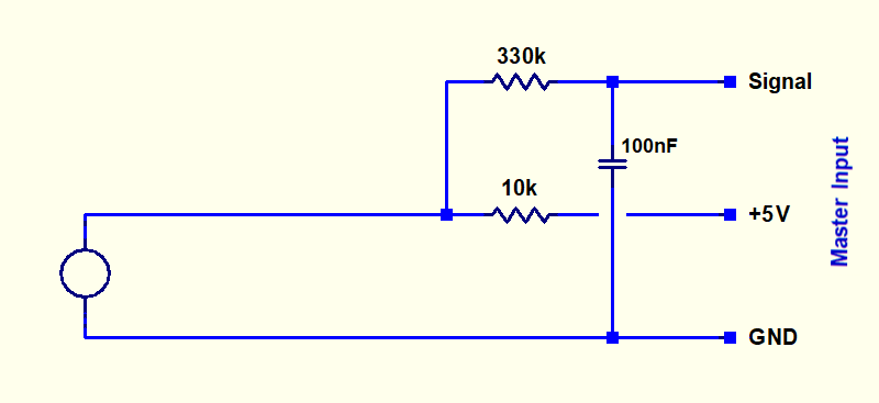
Connect buttons in case of strong electrical noise
The solution shown in the preceding section protects the Master communication with the PC, but it does not prevent short pulse noise being interpreted by mistake, as a manual closing of the button.
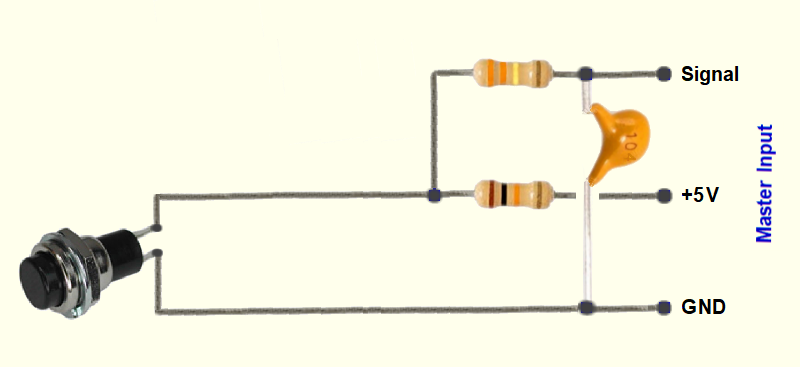
So in harsh environments, for example in the case that the wires pass of the buttons next to the power supply wires of a solenoid or a motor, it is also advisable to add a capacitor. This capacitor eliminates shorter pulses than a tenth of a second and further increases the protection in case of extra-very high voltages.
The two pictures below show the wiring and wiring diagram of these connections (click on images to enlarge).
The next image shows how to make connections directly on the wires (click on the image for a larger view).
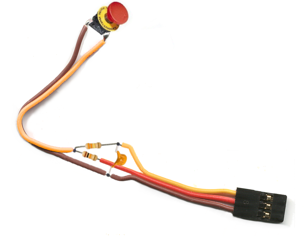
Using a cable with a female connector, components can also be soldered directly on the wires.
Then you could fill the components with a piece of heat-shrinkable sheath.
Alternatively you could use a small base square matrix board.
Recall that when you use these links (with protective resistor), you must set the input pins without PullUp.
Also remember that, if instead of connecting buttons did voltage measurements (so with the Input Pin configured as ADC), a resistor from 330K would cause too much voltage drop, and you should reduce it to 33K. Also in this case the 10 k resistor would and should be eliminated. Furthermore, the addition of the capacitor limits the bandwidth of the ADC to about 10 Hz.
The Master and the Slaves Pin connections
Let us take as an example of having to connect a shielded cable, to carry the signals of three pins and five Volts at a great distance.


You could cut the shielded cable with single connectors as seen here (Click on the pictures to enlarge). Blue wires, Light green and yellow are the three signals, the Red wire is the five volts and the dark green wire is the mass.
But it's a solution difficult to construct and unreliable. These pictures are for a accelerometer, that was moved frequently from one bank to the other of the laboratory. After a few months, two of the five wires broke, above the RCA connectors leading to the Master.
Much better sacrifice three standard extensions:

Extension cords halved provide good quality female connectors, with the wires are well connected and very robust. For a fraction of the price of only connectors you can buy bags of ten standard extensions from Hobby King.
Extension cords connect easily with the son of shielded cable. Cover Thermo-shrinking sheath connections and you get a robust and professional cabling.
Here's a link done right.

The three red wires carry five volts and connect, all together, the Red wire shielded cable. Brown wires are the mass and connect, all three, the stocking of shielded cable. The three yellow wires are InOut signals of the pins 1, 2 and 3 and they are linked to three of the wires inside the shielded cable.
On the opposite side of the shielded cable is the same, with females from the second half of the cables.
In case of long links, Read also This page.
Slaves and Master module modules communicate via serial

The serial line provided by Theremino Master is not a normal RS232 or RS485. But a special line that transmits and receives on a single strand of signal, DPM protocol developed by us. Its advantages are the high speed communication and self-recognition of modules. More info here: technical/protocol

Many Slave modules can be connected to the serial line of the Master.
As for sensors, for serial line connections, using the normal servo extension commands, available at a great price at www.hobbyking.com

Brown = Ground
Red = + 5V
Yellow = Signal
For very long or special needs power connections you can make two-wire serial communication (Mass and Signal), possibly out of shielded cable. More information in the section Long connections and noise immunity
Master and the Computer communicate via USB

Even multiple masters can be connected simultaneously to the same PC through USB lines separated and all of them will be recognized by the same application HAL.
Use multiple USB lines and multiple Master allows in some cases to increase the communication speed. In other cases it may serve to specialize some Master lens and other communications to communicate with channels that require maximum refresh rate.
USB cables should not be special, good quality or particularly courts. We've tried long cables (10 meters) and links with more wires in series (extension cords) and they all worked perfectly. The Theremino system uses the USB protocol 2.0, but it was possible to make connections without errors, through standard HUB, also USB 1.0.
The program keeps HAL communication Hardware modules with the slots


–
THE HAL ( Hardware Abstraction Layer ) simplifies the USB communication and hardware complexity by transforming all signals in numbers “Float” that are written in the input output from 0 to 999 nominated “Slot”, or read by them and sent to the hardware.
.
The Slots
The “Slot” System Theremino are identified with a number from 0 to 999 and are all part of the MemoryMappedFile with name “Theremino1”.
Each slot contains a number “Float” that can be read or written by any component of the system Theremino.

In this picture, only the HAL writes in slots but in reality all system components can be read that write in any of the slots, Although already used by other.
The 1000 available slots are usable freely there is only one rule:
Many applications and many pins can read the same slot, but you should avoid writing in many the same slot, doing so does not break anything but results are undefined.
If you are sending multiple data streams to the same slot then the data are mixed and wins the last one to write, If you want to merge data in an orderly fashion rules are needed.
To establish mathematical and logical rules between the slots, and also to write complex algorithms of behavior, We use "Theremino_Script" or any programming language like C++, CSharp, VBNET, VB6, Python or Pascal, but you can also use Visual languages as MaxMSP, Processing, PureData, LabVIEW and EyesWeb.
For MaxMSP are available plugins and examples here: downloads/foundations
The SLOTs for text strings
SlotText are similar to regular Slots, have similar addresses (from 0 to 999) and they are used in a similar way to them but unlike the Slots, that contain numbers (integers or floating point), SlotText contain character strings.
The characters used internally are of the unicode type to allow writing in different languages (for example Chinese) and use two bytes for each character.
Each SlotText can contain text strings up to 100 thousand characters. If you exceed the 100 thousand characters instead of the text a short error message is written.
SlotText do not use the MemoryMappedFile “Theremino1”, but they use a different MemoryMappedFiles for each SlotText. The names of these files range from “ThereminoSS0” to “ThereminoSS999” (dove ThereminoSS sta per Theremino String Slots).
And finally, SlotText can only be used to communicate between applications and not to communicate with HALs and Master or Arduino modules..
Currently (June 2022) the only applications that use SlotText are:
– QRdecoder, which uses them for the text decoded by the QR-Code and BAR-code.
– Automation (from version 7 onwards), which provides SlotText commands to write and read SlotText.
– SlotViewer, which in more recent versions can use both numeric and text slots.
– Cobot, which can receive commands from the outside and also send asynchronous commands to Automation by means of the event “Commands From Cobot”.
To use the communications between Automation and the COBOT application, read the following pages in the Automation instruction file:
- SlotText
- Event_CommandsFromCobot
- The commands from COBOT to Automation
- The commands from Automation to COBOT
In the folder “Sources” in Automation (always from the version 7 onwards which we will publish by the end of 2021) you will find the new file “Class_ThereminoStrings.vb” that programmers can use to add SlotText to their applications as well.
The Memory Mapped Files
The slots are based on the “Memory Mapped Files” that are little known but very useful.
Communicating with “Memory Mapped Files” is extremely efficient, in a few tens of microseconds can be transferred hundreds of numbers “Float” between separate programs, with different threads and written in different languages.
The “Memory Mapped Files” called “Theremino1” It is long 4096 bytes and contains the 1000 slot used by the system Theremino. All programs of the system Theremino can write and read their data, in the form of float numbers, in 1000 slot of this file.
Each slot is four bytes that when using low level storage functions you must multiply the “Slot” for four to get the index of the byte in the MemoryMappedFile.
Test and example programs, with the sources, in the main programming languages. Using these examples it is very easy to equip any program the opportunity to communicate with the system Theremino.
Also available are the “External” for Scott and Max5 found in file “MaxInstall.zip”. In this way it is possible to communicate “Patch” by Max with the system “Theremino” through the MemoryMappedFiles.
Connections with standard cables
For all the connections between pins, sensors and actuators as well as serial communication are very comfortable normal servo extension commands available at a great price at “www.hobbyking.com” in section “Hardware and accessories” / “Wires and plugs” / “Servo Wire & Servo Plugs”
Standard cable with male-female connector

Brown = Red Gnd = + 5V Yellow = Signal
- For currents up to 0.5 Amps use 26 AWG (0.13 mmq)
- For currents up to 1 or 2 Amps use 22 AWG (0.33 mmq)
More information on connection cables for high currents and very long lines, and target prices and links in the section: connection-cables
Float numbers
(minimum and maximum values valid for Number Slots)
The numbers “Float” are floating point numbers from 32 bit (single precision). Theremino the system always uses the “Float” instead of numbers “Integers” or “Double” for the following reasons:
1) Being long 32 bits are read and written in a single statement of the processor and not require synchronization mechanisms to avoid errors.
2) Although numbers with the decimal point may contain no errors or rounding up any whole number from 000 000 000 -16 ' +16 ' to ' ' 000-odd, and then easily contain the values from 0 to 65535 (16 bit) and even up to 24 bit of the best existing sensors and actuators.
3) Can be used to send 16 millions of different communications “of service” using NaN values (not a number) and NaNs ( Signaling Nan ).
4) They may also contain special values “+Infinity” and “-Infinity”, useful when the calculations produce very high values.
5) The accuracy of the “Float” is from thousands to millions of times longer than the accuracy required, because they are used only to communicate and not to perform calculations.
6) All current transfer 32 bits in a single statement, Why efficiency is highest and two separate programs can communicate in a few microseconds.
For more details on the numbers “Float” read the following pages.
– – – – – –
Float – Single precision, 32 bit, floating point numbers
Positive max: 3.4028235 E + 38
Positive min: 1.401298 E-45
Negative max: -3.4028235 E + 38
Negative min: -1.401298 E-45
Max integer stored without rounding errors : +16' 777 ' 216
Min integer stored without rounding errors : -16' 777 ' 216
Max integer visualized (7 digits rounded): +9' 999 ' 999
Min integer visualized (7 digits rounded): -9' 999 ' 999
+Zero: 0 00000000 00000000000000000000000 (0000 0000)
-Zero: 1 00000000 00000000000000000000000 (8000 0000)
+Infinity: 0 11111111 00000000000000000000000 (7F80 0000)
-Infinity: 1 11111111 00000000000000000000000 (FF80 0000)
Positive NANS
from: 0 11111111 00000000000000000000001 (7F80 0001)
to: 0 11111111 01111111111111111111111 (7FBF FFFF) (4' 194 ' 303 values)
Negative NANS
from: 1 11111111 00000000000000000000001 (FF80 0001)
to: 1 11111111 01111111111111111111111 (FFBF FFFF) (4' 194 ' 303 values)
Positive NAN
from: 0 11111111 10000000000000000000000 (7FC0 0000)
to: 0 11111111 11111111111111111111111 (7FARRAR ) (4' 194 ' 304 values)
Negative NAN
from: 1 11111111 10000000000000000000000 (FFC0 0000)
to: 1 11111111 11111111111111111111111 ( FFFF FFFF ) (4' 194 ' 304 values)
– – – – – –
Special Values
IEEE reserves exponent field values of all 0s and all 1s to denote special values in the floating-point scheme.
Zero – As mentioned above, zero is not directly representable in the straight format, due to the assumption of a leading 1 (we need to specify a true zero mantissa to yield a value of zero). Zero is a special value denoted with an exponent field of zero and a fraction field of zero. Note that -0 and +0 are distinct values, though they both compare as equal.
Denormalized – If the exponent is all 0s, but the fraction is non-zero (else it would be interpreted as zero), then the value is a denormalized number, which does not have an assumed leading 1 before the binary point. Thus, this represents a number (-1)s × 0.f × 2-126, where s is the sign bit and f is the fraction. For double precision, denormalized numbers are of the form (-1)s × 0.f × 2-1022. From this you can interpret zero as a special type of denormalized number.
Infinity – The values +infinity and -infinity are denoted with an exponent of all 1s and a fraction of all 0s. The sign bit distinguishes between negative infinity and positive infinity. Being able to denote infinity as a specific value is useful because it allows operations to continue past overflow situations. Operations with infinite values are defined in IEEE floating point.
Not A Number – The value NaN (Not a Number) is used to represent a value that does not represent a real number. NaN’s are represented by a bit pattern with an exponent of all 1s and a non-zero fraction. There are two categories of NaN: QNaN (Quiet NaN) and SNaN (Signalling NaN).
QNaN – A QNaN is a NaN with the most significant fraction bit set. QNaN’s propagate freely through most arithmetic operations. These values pop out of an operation when the result is not mathematically defined.
SNaN – An SNaN is a NaN with the most significant fraction bit clear. It is used to signal an exception when used in operations. SNaN’s can be handy to assign to uninitialized variables to trap premature usage.
Semantically, QNaN’s denote indeterminate operations, while SNaN’s denote invalid operations.
– – – – – –
Special Operations
Operations on special numbers are well-defined by IEEE. In the simplest case, any operation with a NaN yields a NaN result. Other operations are as follows:
| Operation | Result |
| n ÷ ±Infinity | 0 |
| ±Infinity × ±Infinity | ±Infinity |
| ±nonzero ÷ 0 | ±Infinity |
| Infinity + Infinity | Infinity |
| ±0 ÷ ±0 | NaN |
| Infinity – Infinity | NaN |
| ±Infinity ÷ ±Infinity | NaN |
| ±Infinity × 0 | NaN |
– – – – – –
Summary
| Sign | Exponent (and) | Fraction (f) | Value |
| 0 | 00..00 | 00..00 | +0 |
| 0 | 00..00 | 00..01 : 11..11 |
Positive Denormalized Real 0.f × 2(-b+1) |
| 0 | 00..01 : 11..10 |
XX.. XX | Positive Normalized Real 1.f × 2(and–b) |
| 0 | 11..11 | 00..00 | +Infinity |
| 0 | 11..11 | 00..01 : 01..11 |
SNaN |
| 0 | 11..11 | 10..00 : 11..11 |
QNaN |
| 1 | 00..00 | 00..00 | -0 |
| 1 | 00..00 | 00..01 : 11..11 |
Negative Denormalized Real -0.f × 2(-b+1) |
| 1 | 00..01 : 11..10 |
XX.. XX | Negative Normalized Real -1.f × 2(and–b) |
| 1 | 11..11 | 00..00 | -Infinity |
| 1 | 11..11 | 00..01 : 01..11 |
SNaN |
| 1 | 11..11 | 10..00 : 11.11 |
QNaN |