
Characteristics of the Master module
The form “Master” connects to a USB port (USB1, USB2 or usb3), provides some generic Pin InOut (6, 10 or 12 Depending on the version) and a serial transmission line, toward the Slave modules.

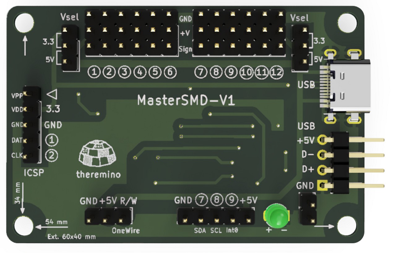 I Master V3 I Master V5 The new SMD Masters V1
Documentation, Datasheets e Download del Firmware
www.theremino.com/technical/schematics
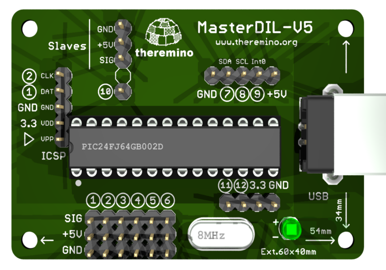
The connector “USB” can be connected to one or two USB ports, to draw a current of 500mA or 1A. The connector “Serial Line to slaves” It is normally connected to the serial line that goes to the slave modules with 3 wires (GND/+ 5V/Data). The fourth pole (Dir) It was designed to connect the device “Master_iso”, optical isolation. It is now used as Pin 10 and isolation, If necessary, with commercial USB isolators. In the latest versions there are also pins 11 and 12.
The Pins 7, 8 and 9 are special, they are the only ones that tolerate input signals from zero to five volts.
And’ also possible to connect more than one Master, with USB and separate transmission lines, in order to increase the possibilities of connection. You can, for example,, use a high-speed communication line, for devices that require a quick refreshment and a second line of communication, slower, for all other.
In This video you see some Master flying machines in China.
Each Pin can be configured independently as:
– Not used
– Digital output
– PWM Output
– Output for servo-controllers
– FAST-output PWM with high-resolution DAC (from firmware V 3.0 onwards).
– STEPPER output to control stepper motors (from firmware V 3.0 onwards).
– Control input the distance reached by STEPPER (from firmware V 3.0 onwards).
– Digital input
– ADC input for switches and transducers
– Input for capacitive buttons
– Input for resistive transducers
– Count input, frequency and period
– Two-wire input for quadrature encoders.
– Entrance for special transducers
Valid configurations with old firmware that they only had 6 PIN
- Up to 6 digital outputs
- Up to 6 PWM outputs for analog digital conversion
- Up to 6 servo SERVO outputs
- Up to 6 DIGIN inputs for digital signals
- Up to 6 ADC inputs for analog signals
- Up to 6 inputs CAP for capacitive buttons
- Up to 6 RES resistive transducer inputs
- Up to 6 COUNTER inputs for counting and frequency measurements
- A quick count and frequency input FAST_COUNTER.
- An input signal period measurement PERIOD and frequency.
or USOUND_SENSOR for Ultrasonic sensors SRF05 or other similar sensors.
Valid configurations with firmware V 3.2
- Up to 10 digital outputs
- Up to 10 PWM outputs for analog digital conversion
- Up to 10 servo SERVO outputs
- Up to 5 FAST_PWM outputs with frequency up to 5 MHz and Duty Cycle resolution.
- Up to 5 STEPPER outputs for stepper motors (more 5 outputs for “direction”)
- Up to 5 the inputs distance reached by STEPPER.
- Up to 10 DIGIN inputs for digital signals
- Up to 6 ADC inputs for analog signals
- Up to 6 inputs CAP for capacitive buttons
- Up to 6 RES resistive transducer inputs
- Up to 10 COUNTER inputs for counting and frequency measurements
- A quick count and frequency input FAST_COUNTER.
- An input signal period measurement PERIOD and frequency.
or USOUND_SENSOR for Ultrasonic sensors SRF05 or other similar sensors. - Up to 5 SLOW PERIOD inputs counting frequencies 16 MHz, for up to over 200 seconds (as an ADC with a resolution of 32 bit).
Valid configurations with firmware V 4.0 (works on all versions of Master)
- Up to 12 digital outputs
- Up to 12 PWM outputs for analog digital conversion
- Up to 12 servo SERVO outputs
- Up to 5 FAST_PWM outputs with frequency up to 5 MHz and Duty Cycle resolution.
- Up to 5 STEPPER outputs for stepper motors (more 5 outputs for “direction”)
- Up to 5 the inputs distance reached by STEPPER.
- Up to 12 DIGIN inputs for digital signals
- Up to 6 ADC inputs for analog signals
- Up to 6 inputs CAP for capacitive buttons
- Up to 6 RES resistive transducer inputs
- Up to 12 COUNTER inputs for counting and frequency measurements
- A quick count and frequency input FAST_COUNTER.
- An input signal period measurement PERIOD and frequency.
or USOUND_SENSOR for Ultrasonic sensors SRF05 or other similar sensors. - Up to 5 SLOW PERIOD inputs counting frequencies 16 MHz, for up to over 200 seconds (as an ADC with a resolution of 32 bit).
- Up to 6 two wire pairs of inputs for quadrature encoders. The maximum counting frequency is around 10 KHz.
The PWM Pin, SERVANT, ADC, CAP and RES can be configured to 8 or 16 bits and connected only to the first 6 Pin.
The Pin type DIG_IN, COUNTER, FAST_COUNTER and PERIOD can be configured with or without PullUp
FAST_COUNTER can be connected to any of the six pins (ten in version 2 firmware) .
PERIOD (or USOUND_SENSOR) can be connected to any of the six pins (ten in version 2 firmware) .
Valid configurations with the new firmware V 5.0 (works on all versions of Master)
The features are the same firmware 4.0, but with the possibility to connect the module Adc24.
Extra connectors for the latest versions of firmware (by V4 onwards)
The six Pin standard lie below and are marked OUT PINS – 1 – 2 – 3 – 4 – 5 – 6
The new PIN 7 located on the connector CN2 – AUX and is marked SDA (accepts signals up to 5 Volts)
The new PIN 8 located on the connector CN2 – AUX and is marked SCL (accepts signals up to 5 Volts)
The new PIN 9 located on the connector CN2 – AUX and is marked Into (accepts signals up to 5 Volts)
The new PIN 10 located on the connector “Slaves” and is marked Dir.
New PIN 11 and 12 I am close to the led.
Master connectors from V4 onwards
With the new Master, version 4.0, the pins are all marked with a circle and number.
Connectors
On printed circuit boards (PCBs V3 onwards), screw connectors were replaced with male-female extension cables connectors. These connectors look less professional, but they are comfortable and reliable. (Screw connectors require a very small screwdriver, It was necessary to tighten them without too much force, to avoid damaging the screw, But if the force was little, with time it became loose. With new connectors instead, connections are fast and safe)
In later versions the connectors are all male and using female-female connector cables.
Voltages and currents
Input-Output pins work with analog signals from 0V to 3.3 V. About connectors is available 5V voltage and a voltage of 3.3 volts stabilized, useful for some sensors. The maximum current for the pins are configured as Output is +/-15mA. For those that are configured as Input you have to limit the voltage from -0.3 Volts to +3.6 Volts and not exceed these thresholds, with currents greater than +/-100uA. Special pins 7, 8 and 9 also accept signals from 5 Volts. (see technical/pin-types For more information about voltages and currents)
Transient errors caused by surges on Input pins
Sometimes, touching the pins with your fingers, the HAL program stops communicating with hardware, writes a red line with the message "disconnected" and you have to press "Recognize". This will occur if the body is charged with static electricity and emits a small electric shock. All components are carefully chosen and never break, But even if you don't see the spark, It's always tension of many thousands of Volts, who send haywire temporarily serial communication and USB port. During the tests we take special care to handle forms only from off, or touch before the mass (for example the USB connector). The final project should always provide an insulated container that prevents users from touching metal parts under voltage.
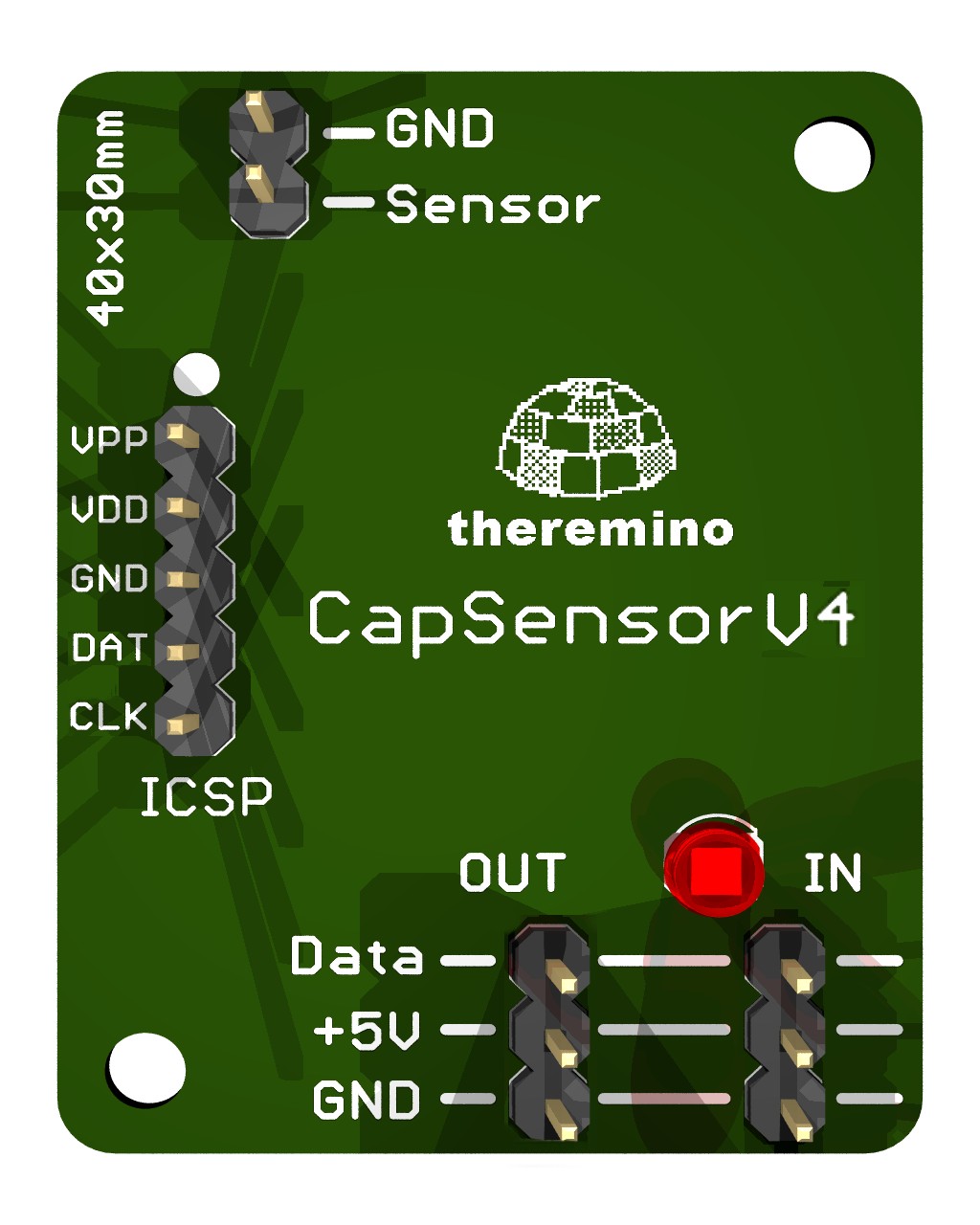
Slave module characteristics “Capsensor HQ – V3”
This slave measures the distance of a conductive object (typically a hand). In the range of distances from a few centimetres to several metres provides performance unattainable with any other tracking system.
Unlike ultrasound sensors tracking is always progressive, cannot in any way “Skip” from a distance at the other, due to the reflections of the signal or detection of multiple obstacles. The detection is always stable and precise with a rapid response time, in the order of milliseconds..–
The CapSensorHQ is perfect for controlling with hand in a linear fashion and always soft sounds and videos features, which Waveform (WAV, MP3, etc.) and movies/music video (AVI, mpg, MP4, etc.)
Since September 2012 version available: 3 of CapSensor (visible in this photo) with improved stability characteristics. Here too the screw connectors were replaced with male-female extension cables connectors. These connectors are less beautiful to look at but they are comfortable and reliable.
Features
- Measurable range of capacity: from 0.001 PF to 10 pF
- Resolution: one thousandth of pF
- Stability: around the thousandth of pF
- Small object detection (a hand): up to a few meters
- Large object detection (an automobile): up to ten meters
- Precision and stability on distance detected: from a few mm to a few tens of cm
- Sensor size vary between square centimetre per one square meter
Technology
A low noise FET analog-to-digital conversion 24 bits provide extreme sensitivity in the capacity measure very small.
Documentation and Datasheets
www.theremino.com/technical/schematics
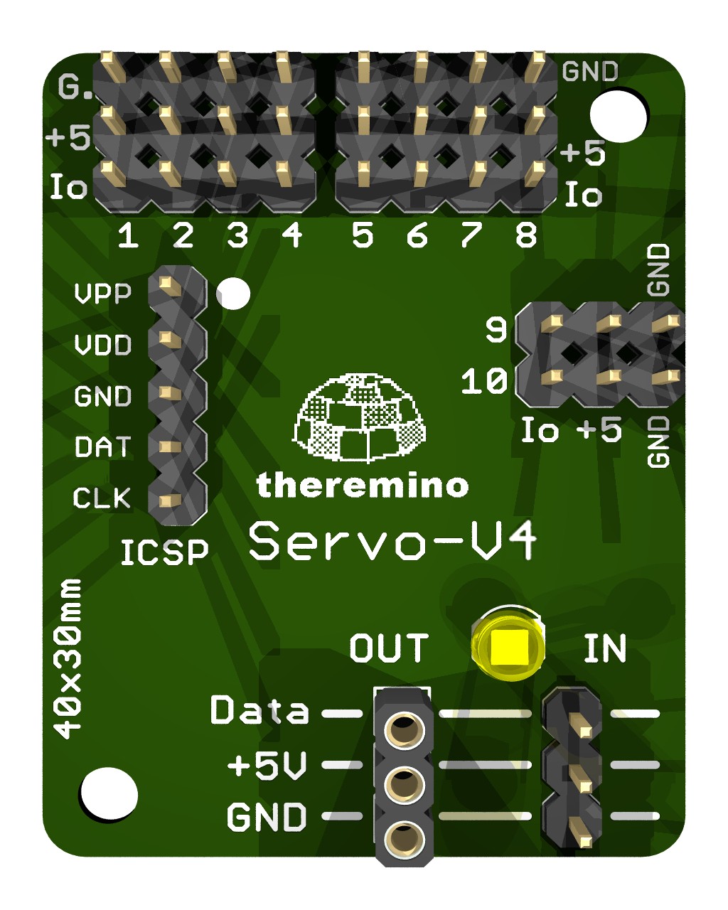
Slave module characteristics “Servant”
SERVO modules are no longer used, instead of using the Masters that have many advantages.
- 12 Pin instead 10
- Safer communication (there is no serial which sometimes stops)
- Configurable pins with many types that are missing in Servos
We leave the following information for reference only
for those wishing to build them and possibly improve them.
– – – – – –
This “Slave” provides ten standard connectors, suitable as “PIN” generic input-output and very convenient for fast connections with the wires standard brown/red/yellow
Each pin can be configured independently as:
– Not used
– Digital output
– PWM Output
– Output for servo-controllers
– Digital input
– ADC input for switches and transducers
– Input for capacitive buttons
– Input for resistive transducers
– Count input, frequency and period
– Entrance for special transducers
Valid configurations
- up to 10 digital outputs
- up to 10 PWM outputs for analog digital conversion
- up to 10 servo SERVO outputs
- up to 10 DIGIN inputs for digital signals
- up to 8 ADC inputs for analog signals (pins: 1, 2, 3, 4, 5, 6, 7, 8)
- up to 8 inputs CAP for capacitive buttons (pins: 1, 2, 3, 4, 5, 6, 7, 8)
- up to 8 RES resistive transducer inputs (pins: 1, 2, 3, 4, 5, 6, 7, 8)
- up to 10 COUNTER inputs for counting and frequency measurements
- a quick count and frequency FAST_COUNTER pin (Pin: 8)
- a pin signal period measurement PERIOD and frequency (Pin: 9)
- a pin USOUND_SENSOR for Ultrasonic sensors SRF05 or other similar sensors (Pin: 9)
The PWM Pin, SERVANT, ADC, CAP and RES can be configured to 8 or 16 bit
The Pin type DIG_IN, COUNTER, FAST_COUNTER and PERIOD can be configured with or without PullUp
Voltages and currents
Input-Output pins work with analog signals from 0V to 3.3 V. About connectors is available 5V voltage (marked V +) (see “Appendices and Tables” current available)
Documentation and Datasheets
www.theremino.com/technical/schematics