SMD code table
Almost all SMD components no longer show the initials but just a code. This trend is spreading and often even have a resistor in place of the value. The engineer's life is hard but this table helps a bit.
Guidelines for PCBs
The main cause of failures are not defective components, but poorly designed circuit boards. Tracks too small, tracks passing between pins of integrated, non-existent insulation, holes that lose the metallization, Touring and many other defects, so common, don't make us more case. If the wiring is well designed components don't break yourself. The cause of the burning of the components is almost always a bad contact, a track that stops or loss of insulation between two PCB tracks.
Everyone is able to make PCB with slopes that make the lap of goose, but get them optimized is harder. You must rearrange the components multiple times and you lose a lot of time.
These guidelines could not be used for complex circuits, such as video cards or MotherBoard of PC, would be too large. But we design small modules only, they can be easily assembled and tested. And small modules can be built to be extra sensitive to disturbances and little reliable.
It's not just about producing reliable PCB but also to get the best performance, decreasing capacitive couplings and the noise picked up from the environment.
Then:
- Generous insulation (at least 0.7 mm). To prevent loss of insulation, even in the presence of humidity.
- Avoid passing between pins of integrated. You can't do that while maintaining decent insulations.
- Increase the insulation in areas with high voltage or high impedance.
- High-impedance and sensitive points to the tracks must be as short as possible.
- Sensitive slopes must be surrounded by mass slopes.
- Make sure the ground loops can behave like a loop and create disturbances. If you are long it is better not to close them completely.
- Sensitive slopes should not mate with capacitively that can be disturbed.
- Double-sided circuits create capacitive couplings between the raceways on opposite sides. To avoid the risk of self oscillate and other flaws it is always better to avoid double-sided circuits.
- Avoid metallic holes, are one of the leading causes of defects in PCB.
- The tracks must be large (about 1 mm) to prevent break for mechanical defects or for the inevitable oxidation which occurs over the years.
- The holes should be large enough to allow you to easily remove the components for replacements or experiments. Just melted the solder components should fall out on their own, It should not be necessary to take them.
- Avoid making absurd turns with tracks. If you can't pass well, rearrange the components, even several times.
- Is worth losing a lot of time to do a good project, It's all the time you save later. The final work is better and doesn't break just looking at him.
By following these tips, the PCB will look different from the current industry standard and could indicate an inexperienced Designer, but it is just the opposite. The real experts can understand why, others simply follow the advice and over time will verify the usefulness.
How to solder
First of all you must use leaded Tin (63/37 on the label). Lead-free Tin can only use it in production, Why preheat the parts, keep all the liquid flux deoxidized added. If you're using it by hand are only pies.
Very important, more important than what you can imagine, you see well and much enlarged. So it takes a lot of light and appropriate lenses (as explained in the next chapter).
Solder well
- Soldering Tip always glittering, If not you have to pass it on the wet sponge, melt pond good and throw it away, reimburse pond good and throw it away… until the tip is all shiny and the pond runs well.
- If it passes the time between weld and the following, the tip must be cleaned again with sponge, fresh pond and throw it away…
- If the soldering iron is too hot, the pond is cooking too quickly and it becomes impossible to keep the tip clean.
- Illuminate it and use quality goggles.
- Place the pieces to be welded so that at least one stand still, best both. Maybe use a small vise or installing more.
- Hold the soldering iron with the right hand (left handed people)
- Keep the pond with the left (right for lefties).
- Keep your wrists resting on the table to stabilize your hands and not tremble.
- Place the welder exactly on the junction between the two parts to be welded. And hold it in place!
- Place the tip of the pond between soldering iron and solder pieces.
- Dissolve a few millimetres of solder and remove him immediately. Welder moving!
- Wait a second or two that Tin stop smoking.
- Blow away the welder.
The seal must be fine in one fell swoop. The welder must be stopped. The pond should run alone without moving the welder. If the solder is not well, do not brush and mess with the welder but unsolder, refresh the parts to be welded and the welder with fresh pond (You should always throw very fresh pond on the table), and start over.
The wires must be stripped to two millimeters, possibly had and preemptively tinned with fresh pond. You can just solder wires prepared well, with fresh pond that flows well and covers them well.
Cool the soldering tip
If the soldering tip is not fully silvered, you have to clean it on the wet sponge (or a wet cloth) and refresh you several times with Tin new.
You must beat the welder on table (This may damage), but beating the wrist on the table and dropping the ball of Tin from the tip of the soldering iron. Then blends into another pond again and splashes back on the table, until the tip is shiny and the pond runs well.
The pond must always run, If it does not flow: clean, clean, clean! Use continuously pond again and throw some of it very much on the table, without fear of waste.
SMD Components
Making prototypes with SMD components is easier than it looks. Just having the right tools and these tools don't cost much.
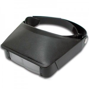
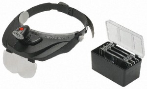
First of all, it takes a lot of light and good lenses
The left model is not good. Small non-interchangeable lenses, closes too head, It is heavy and you can't combine it with prescription eyeglasses.
The right one is perfect, It has four interchangeable lenses of the highest quality and a handy box to store them. The visor is open and lightweight and stands up easily on the head when not in use. And finally, costs very little, less than 10 Euro on eBay.
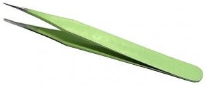
Then it takes small-tipped tweezers and soldering iron and the pond right
The end of the soldering tip must be of 0.8 mm in diameter and the tweezers must be smagnetizzate and with tiny bit.
The pond must have a good soul flux, must be thin (0.5 mm approx) It should contain the right percentage of lead (Note 1). With the lead free Tin solder cannot be manually, only the machines they succeed. It is not forbidden to use Tin with lead, in fact all dealers as Farnell, Mouser and RS have to catalog. What is prohibited is using it for industrial production.
(Note 1) The pond with lead, in percentage 63/37, is an alloy “Eutectic”, i.e. go away, from liquid to solid, without crossing the stage doughy and soggy. When welding manually, It is not an industrial production, There is the risk of polluting the soil and groundwater, with thousands of pieces. And even there is a danger of inhaling lead, because lead has a high vapour pressure and does not evaporate, with the poor 300 degrees used to weld. The only precautions to be taken are not to eat it and wash your hands, before you touch food. When welding, It may be a good idea, use a vacuum cleaner for the fumes, but serves for the vapors of flux, not for lead.
Do PCBs with adhesive copper tape
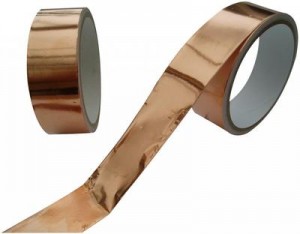
Once accustomed to working with SMD components, It turns out that they are more comfortable traditional components (You should not pass them through the holes). You can build circuit boards in five minutes with the copper adhesive tape, easily available on eBay.
ATTENTION: This technique should be used only for small modules, with few components. You can also do more, but it takes patience and inhuman abilities!
Before you do the project on Eagle. Must be single-sided and well designed, read the guidelines at the top of this page.
Then you cut the traces with scissors and apply on a copper vetronite without support (or even out of nylon or plastic support). With this technique, and since you don't have to make holes, the small circuit boards are made in minutes.
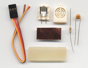
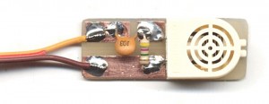
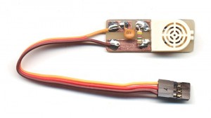
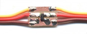
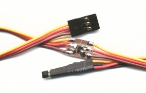
First example: A moisture sensor adapter
Click on the pictures to enlarge
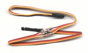
Even common components can be used as SMD and this adapter splits into two minutes.
Copper adhesive is very strong from cold but when it gets hot it loses tack. Then use large runways and prepare the bent parts and tinned on duty. Solder points where they soldered terminals and finally weld, warming up for a short time.
If you learn the technique the result is reliable and very robust. Also pulling strong tear before the threads of touring.
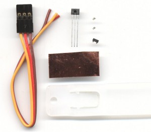
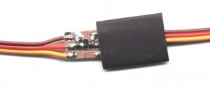
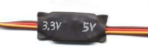
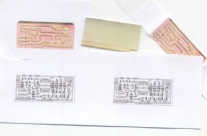
Second example: Adapter from 5 Volts to 3.3 Volts
Click on the pictures to enlarge
The base of this adapter is a material “impossible” a scrap of plastic that melts with the heat. Equally it has been possible to build a robust and reliable adaptor. Warming the right, without loosing all you get good strength. The pads stick to the melted plastic, so much so that by pulling, tear before the threads of touring.
These adapters can be used for magnetic sensors, for potentiometers and for some humidity sensors.
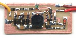
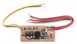
Third example: High voltage generator for ion Chambers
This is an example really “extreme”. More than anything else was a test to see if you can do it. And the result was positive. It takes patience and skill but “You can do”.
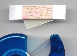
You are a piece of copper vetronite adhesive tape. You print the full scale PCB. Fold the piece of paper printed behind the PCB and fastens with clear tape. You could also smear a little’ Glue for paper, over the entire surface, to prevent paper will fragment and move during the incision.
You take a “Cutter” sharpened or a scalpel and affect all edges. Better to use goggles and plenty of light.
After recording the edges removing the paper. It doesn't matter if some edge is not completely cut. You check the original design and finish missing cuts with a scalpel. Finally, with a small screwdriver, you undermine and destroy all copper parts, between one track and the other.
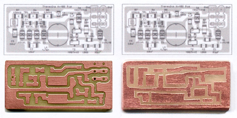
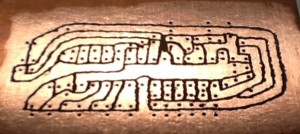
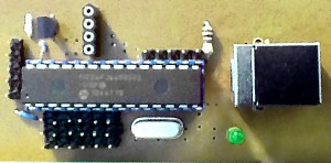
The PCB on the left is done with the cutter, the one on the right is made with adhesive copper tape.
Don't mind to the connectors on the right, the latest ion Chambers have "connections" different and it only takes two wires soldered, without connectors.
And here is the final. Not only can you do, but it can be done in half an hour. Click on the pictures to enlarge.
Milling the copper
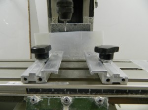
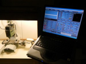
To make the prototypes we run a CNC milling machine. It is not easy and the first few weeks, or months, doesn't end anything good. Even experienced the cutter is good only for small prototyping and anyone acting on many. If you have to make a PCB every now and then it is better to get them done by specialized companies like, for example,, MDSRL. Choose the single face, shipping to 15 days and help it do a dozen. If they are divided with other auto-manufacturers spend a few euros and the result is much better, than what you would get with the cutter.
Some of our DIYers have also made the Master modules by cutting the tracks by hand in fiberglass with the Dremel.
But this is a difficult art, few people know how to do and the results are beautiful to look at. Equally these artistic works have worked flawlessly.
Linear and logarithmic scales
In recent months some experimenters have changed the Lightning sensor, turning it into a EMF meter. When confronted with a commercial meter, they found that the answer is different. Commercial meter, a few meters from the source, measure virtually zero. Instead our detector goes away very much. The limit must be brought outside, far away from any electrical equipment. And even then it, the measured signal will not reset.
The reason for this different behavior, is that commercial meters, have the linear scale, While our circuit is inherently logarithmic. The logarithmic scale is a virtue. Is measured with great accuracy, any signal, without ever changing scale. Instead with a linear circuit, you normally use, at least four scales, ranging from the user and switched that must be set one by one.
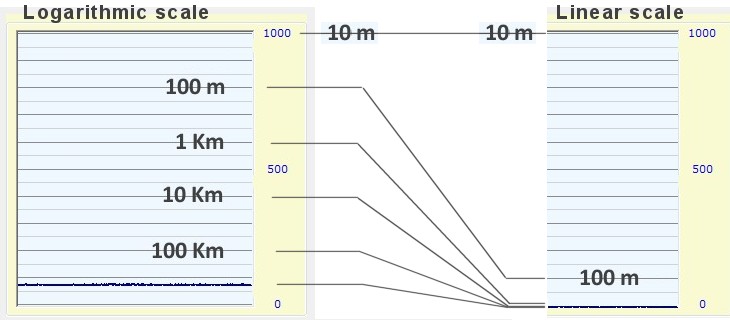
This image shows, How would the scale of our lightning sensor, If we had used a circuit, with linear response. All lightning, with distance from a kilometer up, they would crowd into Victoria, in one line to zero.
Linear scale measurement, We should add, a flow switch. And it would take five courses (from 10 to 100 meters, from 100 to 1000, from 1 to 10 Km, from 10 to 100 Km and finally by 100 to 1000 Km)
Scales to measure electromagnetic fields
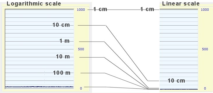
For EMF is better use stairs with shorter distances, as in the image below. Or better yet, scales calibrated in volts per meter (electric fields), or Gauss per meter (magnetic fields).
An EMF meter using up close, at most a few hundred meters from the source. So it has to be less sensitive than Lightning Detector. The scale should go from centimeters to meters, rather than hundred meters to hundreds of kilometers.
To reduce the sensitivity, to electromagnetic fields, just reduce the number of coils, of the sensor (magnetic fields), or the length of the antenna (electric fields).

