
")
The Theremino_MCA while being completely Freeware and OpenSource is a true multi-channel-laboratory Analyzer.
More information:
– Electrical schematics and Assembly plans: www.theremino.com/technical/schematics
– Software: www.theremino.com/downloads/radioactivity
– Hardware, DIY and kits: www.theremino.com/contacts/producers
– Images and videos: www.theremino.com/video-and-images
– Article about Open Source Electronics: crafts-to-gamma-spectrometry-signal conditioning-of-
——————-
Hardware for the Gamma spectrometry


The Theremino_PmtAdapter contains a feedback loop that can keeps the tension stable even in the presence of strong temperature fluctuations. In this way the calibration remains accurate over time and rows of isotopes do not move and do not expand.
ATTENTION: For optimal performance use pipes PMT wired as shown in the file PmtAdapters.pdf – PMT for low impedance tubes (with resistors 1 Mega or even from 560k) cannot operate with these adapters. To use them you should replace their resistors, as indicated.
This adapter can be used with the well known freeware software PRA (We thank Marek Dolleiser for having paved the way for this kind of analysis, its software PRA is a reference for many years and helped a lot) but only with the Theremino_MCA you can do filtering and deleting useful background to get maximum information within a reasonable time.
This file includes the design of PCB, le immagini e le simulazioni SPICE: PMT_Adapter_V3.1
This is version 3.2 con molti piccoli miglioramenti: PMT_Adapter_V3.2
This is version 3.3 con ulteriori miglioramenti: PMT_Adapter_V 3.3
Most salient features:
– Compact only 50 X 70 mm
– No initial thermal drift due to the feedback loop.
– Adjustable voltage from 500 to 1500 V
– Very low power consumption only 10 mA @ 5 V
– Very low ripple only 100 UV
– Protected against short circuit
– Maximum power output 100 MW
– Preamp circuit and pulse enlargement (from 3/5 uS to 100 uS to be read by a PC sound card)
Caratteristiche tecniche:
– Compact only 50 X 70 mm
– No initial thermal drift thanks to the feedback circuit.
– Adjustable voltage from 500 to 1500 V
– Very low consumption at 5 v only 10 mA
– Ultra-low ripple only 100 UV
– Protected against short circuit
– Max power output 100 MW
– Preamp circuit and widening of built-in impulses (carries impulses from 3-5 us to 100 us to be read by a PC sound card)
The simple and neat reduces manufacturing defects and makes them readily apparent.


In the following pictures you see the PMT in rehearsal.


The circuit diagram and an impulse to sample that shows the noise level of ’ power supply, Note that this is a low-energy pulse.


In the latest versions of PmtAdapter noise is less than 100uV. Practically the only noise due to sampling in 16 bit soundcard, as shown in the two following images.


The first picture shows only noise sound card, the second noise with a separate connected.
——————-
The complete system


———————
The Pmt Adapter is not in production, You can build it but contains a number of special components, hard to find and expensive. So we recommend that you contact Lello, who knows how to find a cheap components and also print a number of PCB for friends: ufficiotecnico@spray3d.it
The theremino team only deals with research and does not sell hardware. The system is completely "Freeware", "Open Source", "Not for Profit" and "DIY", but there are manufacturers who can provide modules assembled and tested at a great price. One could hardly self-build them spending less. For a list of the producers read this page: www.theremino.com/contacts/producers
A hoof to the Hamamatsu PMT R6095 (and the like)


In this ZIP file the complete project Eagle and the GCode for the cutter: PMT_Socket


These pictures show how to adapt the connectors to printed and how is the plinth ended (click on images to enlarge them)
The capacitor might also be welded across (with two insulating sleeves on leads) and, to avoid short circuits with the outer aluminum tube, It is good to wrap the whole area from PMT to printed circuit board, with a sheet of plastic sheet..
An MCA system for Apple (iPhone and iPad)
By popular demand Alessio has designed a special version of PmtAdapter, usable with software available on iPhone and iPad. The software is called Geiger bot, ed è un riferimento per la comunità Apple.

The circuit diagram is very similar to PmtAdapter for PC, but I added a battery (There is the ’ USB powered). The signal amplitude is reduced considerably, You can send all ’ mic input, that otherwise would saturate and would distort the pulse shape.


Here you can see the spectra obtained with Americium and cesium. Thanks to the wonderful display resolution “retina”, the words are so small, that do not disturb the vision of the beautiful black background.
We are light years away from a true MCA, line width “FWHM” (that is the most important parameter for an MCA) is overwhelming. Minor details of the spectrum are completely invisible. Here's the same Spectra produced by Theremino MCA:


With a Tablet 12 inches by 180 Euro (with Windows 10 and shipping included in price), you would have a portable instrument much more convenient and accurate. But the satisfaction of using an Apple system, It costs an exaggeration, is priceless!
Calibration and temperature
The Pmt Adapter and the photomultiplier consume only a few tens of milli Watts, that are insufficient to cause significant temperature variations. So you don't have to wait for a “warm up time” between the ignition and the measures. And there ’ is not even a progressive warming during very long measurements.
Though the crystals change with ambient temperature performance scintillators, as you can see in the image below:

Note that the response to temperature is not linear and that changes even slope from positive to negative, right in the area of normal temperature. Whereby an automatic correction would be inaccurate. It would take a correction table to be calibrated for each Crystal and this would be very complicated and ultimately unreliable. Much better make an adjustment with two markers before each measurement.
Check with the marker before each measurement is quick, accurate and very reliable. It is recommended to keep in place two small samples (for example, Caesium and Americium) at appropriate distances, so you always have two small rows of reference. Caesium is weaker and you hold it close enough to the probe while l ’ Americium hold about ten centimeters, or is enclosed in a capsule, to decrease its activity and keep him close to the probe.
The two lines should be the same height and small enough not to disturb the measurements. If you do not have to measure precisely the cesium and l ’ Americium, then the two markers can always stay in position. See their lines on the final chart (possibly commented) from the security that the chart is perfectly calibrated.
Build a well in lead
To use to measure the level of radioactivity and radioactive substances, natural background.
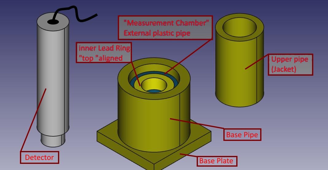
The measure consists of a base plate, plus some concentric cylinders, of various sizes and thicknesses. Among the components leaves something’ of slack, in order to facilitate the Assembly ’.
The material is actually brass lead, to distinguish it from the ’ probe grey aluminium, While the piece of inner cylinder (barely visible) is the unique ’ of plastic, with concentric ring in lead.
All the lead parts were made from sheet metal 1,5 mm thick, cut with a common Bill-sheet and shaped by hand, wrap around cylinders of aluminium/steel/plastic I had available (used only as “DIME”).
The base plate is made by folding several times a strip of sheet metal of equal width, getting a decent thickness.
Sheet bends easily around the straight edge of a table and flattens with hammer taps. The lead is very malleable.
All the pieces were wrapped with paper wide enough, so handle them does not come into direct contact with lead, that tends to get your hands dirty. Also why is good to calculate a little’ of slack between the various diameters of pieces, so then that paper coating doesn't break any insertion/extraction of cylinders all ’ same, that partially must fit one inside ’ more (as for the cylinder and top shirt)
To measure you follow this pattern:
- First arises on a table the base plate and the cylinder base;
- You insert the sample to be tested in the base tube, so that it touches the inside (lower) Dell ’ ring of the measuring Chamber: You can tuck under to it appropriate spacers;
- You put the measuring Chamber (plastic cylinder and lead supportive ring) so the below sample is centered on the bottom of ’ ring;
- He slips his shirt more than basic ’ inside the cylinder: It will support the plastic pipe and concentric ring of ’ will lead to the hole to allow subsequent insertion of the probe;
- You insert the probe : in my case straight draw in ’ ring of lead measuring nursery.
From the tests I've done this setup reduces background noise for almost 20 CPS to 3,1 CPS
Marco Russiani
Download this project, complete with more information and pictures:
![]() Theremino_Pozzetto_di_Misura_ITA.pdf
Theremino_Pozzetto_di_Misura_ITA.pdf
![]() Theremino_G-Ray_Test_Chamber_ENG.pdf
Theremino_G-Ray_Test_Chamber_ENG.pdf
Currently using Dolleiser’s PRA (Pulse Recorder & Analyser version 15.0.1.0) would very much like to try the MCA unit as described. Where do I obtain the hardware and software? This is a small research project for Dully Research Inc.
Regards, Marty
Our software is Free and Open Source, you could use it with your hardware, download it from here:
https://www.theremino.com/en/downloads/radioactivity#mca
Our hardware is explained here:
https://www.theremino.com/en/technical/schematics#pmtadapter
If you can not make it DIY then you could write to Alessio that helps the Makers with components and preassembled parts: alessio.giusti@meteolink.it
Addition info about radioactivity and spectrometry:
– Electrical schematics and Assembly plans: https://www.theremino.com/en/technical/schematics
– Software: https://www.theremino.com/en/downloads/radioactivity
– Hardware, DIY and kits: https://www.theremino.com/en/contacts/producers
– Images and videos: https://www.theremino.com/en/video-and-images
In the download page and in the application folders you will find many useful documentation.
thank you for your prompt response, very much appreciated will follow your steps as outlined.
Sig Cicala,
I really appreciate your paper “Tecniche di condizionamento del segnale per la Spettrometria Gamma”. Unfortunately I speak almost no Italian. So I used a few Linux programs and Google translate to convert your paper to English.
It may not be of any use to you, but if you would like my English translation of your paper — I would be honored to email you a copy.
My project will most certainly build off of your work and I have already credited you on my project blog.
This is a good idea, thanks!
You could send the file to engineering@theremino.com and we will publish it.
Excellent and decent post, I found this much informative, as to what I was exactly searching for. Thanks for such post and please keep it up.
Thank you for your great work. We are using the Theremino MCA 7.1 software in our university research and we are very happy with it (in combination with a Gamma Spectacular driver and an X-ray probe).
One problem we have is that the background spectrum (zero input, no sources) looks different when I connect to the computer that runs Theremino MCA 7.1 remotely via Teamviewer. In that case, we start to get much more counts/noise/pileup in the low KeV region. When I disconnect from Teamviewer and start a new run, then the counts in that region are down again.
I suspect this has to do with the CPU load of the computer that runs Theremino MCA. Teamviewer adds about 20% CPU load when connected. I suspect similar issues may occur when the CPU load varies due to other reasons e.g. due to Windows Update, virus scan etc. This is a problem for us since we need to have a high reliability of baseline spectra, as long as no source is present. Have you encountered such an issue before i.e. that the spectra change depending on the CPU load even if the input signal remains the same (background with no source in our case)?
Tested now with TeamViewer and no difference in noise observed.
So I suggest to make further tests in the following areas:
– The Audio-Recording panel properties (Maybe you selected stereo-mix instead of microphone? Maybe you are not using the modifyed audio card? Maybe some recording property changes when TeamViewer uses the audio?)
– The TeamViewer audio preferences. Try to set properties to not use audio.
– The power supply that comes from the USB and goes to the audiocard (maybe the 5 volt noise increases when using TeamViewer).
Thank you very much for your quick response, Livio. I will carry out more tests here and will report back with more detailed information.
Hi Livio, I observed this issue over time and I think the last suggestion that you made was the solution: once I switched from the computer’s USB 5V supply to a lab power supply with 5V DC, the problem stopped to show up.
We use the Gamma detector close to an ultrasound transducer. When we’re very close, we sometimes get pulses which are clearly not due to radiation but due to certain kinds of ultrasound-induced mechanical vibrations affecting the detector. Fortunately, in the pulse shape visualizer, I can easily identify those “fake” pulses because they don’t have a real peak and stay up for a long time. See the screenshot here: https://ibb.co/dXJmFv. Unfortunately, Theremino MCA still recognizes them as valid pulses. Would it be difficult to change the Theremino MCA source code such that these type of fake pulses without real peaks are filtered out and treated as invalid? Thank you for any help or any advice!
The pulse detection code has been stable for many years and works so well that we prefer not to risk generating defects. And anyway it would be just a patch.
Since you see impulses, it should not be difficult to find a solution to eliminate them.
Inside the probe there is a very delicate photomultiplier tube containing metal grids and thin links. Certainly the ultrasound generates resonances in some of these connections. It is also possible that some of these details of the PMT tube will break because of vibrations.
I therefore suggest finding ways to mechanically isolate the probe.
Thank you very much, Livio, for your advice. I tried my best to mechanically isolate the probe with all kinds of foam and damping materials. This helped a lot and reduced the occurrence of the fake peaks maybe by 95%. However, we still get some fake pulses and therefore unreliable results, so I decided to finally consider filtering the remaining ones out on the software side.
I completely understand that changing the main branch of the Theremino MCA code is risky, given how well it works. Instead, I was thinking about making a few small adjustments to the source code on my computer (i.e. reject pulses that stay up) and recompiling locally.
I have a lot of programming experience but not so much with VB, so it would help a lot if you could briefly point me at the file in the VB project where I have access to the data for every pulse that is visualized in the pulse shape visualizer and where it is determined whether a pulse is valid or not. Just pointing at the right file/place in the project code for me to look at, would be super helpful. Thanks a lot!
1) Please install Visual Studio 2008 as explained here:
https://www.theremino.com/en/downloads/notes-on-software#development
2) Set the visual studio ambient as explained here:
https://www.theremino.com/en/downloads/notes-on-software#visualstudio
3) Open the “Class_WaveRecorder” and find the function “DataArrived” at line 146
All you need is in the “DataArrived” function, good luck.
Hi I am layman in radioactivity and mass spectrometry, but for various reasons I needed to know if you can recommend a sensor similar to this one with similar characteristics ihttp://www.atomtex.com/en/products/radionuclide-identification-devices-rids/at6101-at6101b-spectrometers
to use with theremino, I would add that the particularity is that it must be very sensitive and directors I mean I need to locate gamma sources although a few mm and very weak…Thank you
With the theremino you could build something very similar and with the same performance.
You need a photomultiplier, a Crystal NaiTl, a PMT adapter, the application Theremino MCA and a Tablet with Windows. Parts from the application Theremino MCA and you will find links to everything else:
https://www.theremino.com/downloads/radioactivity
Unlike the device you specified does not have an LCD Panel and buttons but you'll need to use a Tablet with touch Screen (or a desktop for laboratory measurements).
If you want help for building ask to Alexei, There's his email address here :
https://www.theremino.com/contacts/about-us#alessio
Recommendations
– – – – – – – – – – – –
The device that's already shown promise heaven and Earth but “forget” explain that the reality is much less pleasant than it looks to read its features. First of all these devices seem to measure towards the front but are not at all keys. More go next to the stream with the tip and more mark, all there. But if it turns sideways and go next to the stream with the tip mark equal. If the source is small enough that you go to a meter and do not score nearly nothing left. If it is large (for example all around you) then you turn around and you're still measure the same.
Another aspect which does not appear to read what they wrote is that sensitivity to low radioactivity you pay with time. To measure low radioactivity, just above the bottom environment then we go around with beautiful handle that show in their image but the power is switched on and you leave it idle for an hour before having steps reasonably accurate.
It would be different if you worked in a nuclear power plant and go around with the suit. In this case you could make rapid measurements, Let's say thirty seconds. But I don't think that's the case.
Finally, it must also be said that the isotopes that normally can be found are four or five. The other hardly can find out from a central or by medical laboratories. And it also takes a lot of experience to understand something reliable by specters. So if you do it to learn it's fine, But if you plan on using it actually things change. Things to study for months or years and eventually measure more or less what there was to be expected. A little’ of caesium in environment, some sample testing and no more than useful.
Hello Livio, and thanks for the reply, about the aesthetics of the project doesn't interest me much but more than anything else the substance ... I go straight to the problem so you know what it is: I would like to locate nodes Hartmann.
In his book "the health of the Habitat" nuclear physics professor Katie Lamkin (He taught at Harvard Univ. and La Sapienza of Rome), explains how he discovered the nodes hartmann,(what feasible so far only from psychics with chopsticks) with an infrared thermography or with a nuclear spectrometer probe in German (He also used the CERN in Geneva and of ENEA) or Geopotenziometro (I don't know ...).
at those points found an ionizing gamma radiation, very weak one micron thickness of radio226. This radiation potratta for hours can create very serious diseases and geopatologie, and the only place where we're so many hours is the bedroom, so it would be good to revisit this area with this tool. Also if I remember correctly the potassium-40 influence much the thyroid and could see even with a thermal imaging to the hundredth of a degree that this radiation produced a hypothermia, Although very weak.
The spectrometer reported to me with a link is one of that used by him,If I understand correctly, What I'm asking is if it's worth diving into this venture that fascinates me.
I mean I could build with an undisclosed amount too much expensive (also a few hundred euros) a similar tool? (to Lamb costs over 30,000 and) or the detection could be an arduous task since the network with these nodes are spaced approximately 2 m and placed in an area of a few mm or even microns!?
Thank you
You can build it with less than 300 Euro. Ask to Alexei for greater precision.
In my experience you'll measure not nothing significant, just noise and random events. But history is full of things thought impossible that then were true, so if you really care about it you should try it.
I'm sorry,but I can't find your email….on this site and wetteruseful there is
The are : Contacts / Partners / Alessio
And’ a little’ Masquerade : “Mail: makers at theremino dot com”
But it means : makers@theremino.com
Hi
Thank you so much for your valuable site.
I’d like to know the maximum number of pulses per second that we can count using your device.
I would be very grateful, if you could give me your feedback.
Regards,
Amir.
What device, the GeigerAdapter or the PmtAdapter ?
In the first case (The geigeradapter) it depends from the Geiger tube used.
Tubes heve normally dead times from 50 to 250 uS
Tubes with a dead time of 50 uS can count to about 10’000 pulses per second.
Tubes with a dead time of 250 uS can count to about 2’000 pulses per second.
If you plan to use the Geiger Adapter with so high radiation levels then it is better to configure the Master input as FastCounter (not simple Counter).
In the second case (A separate) it depends from the gaussian shaping circuit that produces pulses of about 100 uS.
So the max counting rate will be about 5’000 pulses per second.
Thank you for your detailed reply.
But this count rate is so low for most applications. We need to count more than 50’000 pulses per second for our application at our lab. I would be very happy, if you could give me your suggestions about the suitable circuit for this purpose.
Regards,
Amir.
It is not a “circuit” problem, no geiger tube could count 50000 pulses per second.
And if, supposedly, you have a tube that emits more than 5000 pulses per second, instead of making measurements, you should run away as quickly as possible.
So there must be some misunderstanding. First of all, are you talking about a geiger tube? So what type of geiger tube you intend to use? And what source should emit these incredibly strong radiations?
For high intensity radiation fields, what you need is an ionization chamber to measure the current directly. Or a special GM tube that measures Current directly, which is called Big Current Counter Tubes.
Yes, this is correct.
For 50000 pulses/second you can not use geiger tubes and our application Theremino_Geiger.
hello,
I would appreciate any help with my problem.
I attempt install Theremino_OSC_UDP_Linux_V1.0 but run into a problem i can not solve.
Essential it is a missing system dll – but I do not know which one.
the debug level “critical” gives the output below.
Best wishes
Erich
Unhandled Exception:
System.TypeInitializationException: The type initializer for ‘Theremino_OSC.Theremino’ threw an exception. —> System.DllNotFoundException: ThereminoSlots
at (wrapper managed-to-native) Theremino_OSC.ThereminoSlots+MemoryMappedFile_Unix:the_slot_init ()
at Theremino_OSC.ThereminoSlots+MemoryMappedFile_Unix..ctor () in :0
at Theremino_OSC.ThereminoSlots..ctor () in :0
at Theremino_OSC.Theremino..cctor () in :0
— End of inner exception stack trace —
at System.Threading.ThreadHelper.ThreadStart_Context (System.Object state) in :0
at System.Threading.ExecutionContext.RunInternal (System.Threading.ExecutionContext executionContext, System.Threading.ContextCallback callback, System.Object state, Boolean preserveSyncCtx) in :0
at System.Threading.ExecutionContext.Run (System.Threading.ExecutionContext executionContext, System.Threading.ContextCallback callback, System.Object state, Boolean preserveSyncCtx) in :0
at System.Threading.ExecutionContext.Run (System.Threading.ExecutionContext executionContext, System.Threading.ContextCallback callback, System.Object state) in :0
at System.Threading.ThreadHelper.ThreadStart () in :0
[ERROR] FATAL UNHANDLED EXCEPTION: System.TypeInitializationException: The type initializer for ‘Theremino_OSC.Theremino’ threw an exception. —> System.DllNotFoundException: ThereminoSlots
at (wrapper managed-to-native) Theremino_OSC.ThereminoSlots+MemoryMappedFile_Unix:the_slot_init ()
at Theremino_OSC.ThereminoSlots+MemoryMappedFile_Unix..ctor () in :0
at Theremino_OSC.ThereminoSlots..ctor () in :0
at Theremino_OSC.Theremino..cctor () in :0
— End of inner exception stack trace —
at System.Threading.ThreadHelper.ThreadStart_Context (System.Object state) in :0
at System.Threading.ExecutionContext.RunInternal (System.Threading.ExecutionContext executionContext, System.Threading.ContextCallback callback, System.Object state, Boolean preserveSyncCtx) in :0
at System.Threading.ExecutionContext.Run (System.Threading.ExecutionContext executionContext, System.Threading.ContextCallback callback, System.Object state, Boolean preserveSyncCtx) in :0
at System.Threading.ExecutionContext.Run (System.Threading.ExecutionContext executionContext, System.Threading.ContextCallback callback, System.Object state) in :0
at System.Threading.ThreadHelper.ThreadStart () in :0
WARNING: The runtime version supported by this application is unavailable.
Using default runtime: v4.0.30319
We abbandoned all the Linux (and Mac) developments because there are too much problems.
Maybe you could try with Wine.
You could also write to our Linux expert Roberto at: development@theremino.com
Sorry
Livio
Hello,
I am wondering if you have a recommendation for a NaI Scintillator manufacturer?
Mainly you find on Ebay Probes from Gammaspectacular. I guess they would match. Gammaspectaular is also providing a MCA (e.g. GS-1100-PRO). Does the MCA fit somehow to Theremino MCA?
Secondly I find some units from Scionix 38B57. Do they need to be changes like you described in “Strange wired PMT tubes”? Or only when they have separate Power and Signal output.
The other option I found are those “Turnkey MCA sytems from the US. They have their own software (seems proprietary) using a PicoScope with 10MHz Bandwidth. I am also wondering if that may work together with Teremino (I guess no). But the idea with a chep DigiScope instead of a soundcard sounds interesting. Do you think the higher bandwidth may be a benefit? But those scopes cannot stream continuously, so I am wondering how it is done exactly…
Finally, I am wondering how to forward detected pulses from Theremino MCA > Theremino Geiger. It is mentioned that this works somehow only using software, but how?
Thank you,
Martin
If you use our PmtAdapter then the photomultiplier MUST be have an high impedance resistor chain. Otherwise any PMT tube can work, but you get more noise in the low energy area.
The Theremino_MCA application works only with an audio card input.
The Theremino_MCA application is written for the audio card signal (with a gaussian conditioning circuit that limits the band to 20 to 100 KHz max) it will not work with a 10 MHz band.
I would recommend using exactly the PMT tube and the PMT adapter we designed. In my opinion, any change over our project will only worsen the performance. Read this document:
https://www.theremino.com/wp-content/uploads/2012/11/MinimizingFWHM_ITA_ENG_PDF.zip
Hello again,
to my question before: I noticed that it is possible to use GS-1100-PRO with termemino => answered.
How do you estimate the GS-1100-PRO in comparison to Theremino MCA?
Thanks,
Martin
It will work and could be a good idea if you need a complete (non DIY) system.
We have not tested it.
Maybe you will get a little more noise in the low energy area but it will work very well.
I am using Teremino MCA with a geiger tube connected just for the purpose of counting and forwarding the impulses to Theremino Geiger.
Unfortunatelly, it counts much more than what is really there.
E.g. counts 60/s, I get 180.
I tried to change almost anything possible on the options.
Before I hat 50us peak length that worked, but now peak is 75us rectangular and has a slight overshoot at the end and ripple in between, I think that this is counted as peaks as well.
Is it possible to simply use a threshold and noise level and thats it? Or how do you think I may resolve it.
Solved… I am using AudioInput that works. If you still have a solution based on MCA please let me know. I’ll try older versions till then…
The application MCA requires gaussian shaped pulses coming from a photomultiplier tube. So geiger pulses are not correctly recognized.
You must read the geiger pulses directly with the Theremino Geiger app.
There are three metods:
1) A “Geiger Adapter” and a “Master module”
2) The application “Theremino Bridge”
3) The application “Audio Input”
https://www.theremino.com/en/technical/schematics#geigeradapter
https://www.theremino.com/en/technical/schematics#masterv5
https://www.theremino.com/en/downloads/radioactivity#bridge
https://www.theremino.com/en/downloads/multimedia#audioinput
Hello Livio,
Greetings from Australia.
Glad I found this page.Thank for all your inspiring work and those of the team Theremino. After reading the the theremino history I can see how it all came about and showing that with
love of a subject great things are possible – inspiring.
This is what wrote today to nkom but it seems to be appropriate here too. I cannot attach the spectra here but can send them if you like by email:
A few days ago I finished the basic build of a low noise battery power supply for a PocketGeiger type 4 for the Iphone from Radiationwatch.org in Japan and managed to take two spectra before the unit stopped working. I might have blown it up somehow but since ordered a replacement.
The spectra are attached and should show Am241 and Thorium but show something completely different. Has this to do with the pulse lenght which is meant for the Iphone mic input or is there perhaps another reason? What can I do to fix this?
I also noticed on the spectra that they only display spectra down to about 15 KeV. Is there a way to display spectra down to say 2 KeV?
The X100-7 diode used in the PocketGeiger shows in its specification graph a high sensitivity starting in this range and that is the reason for me using it for my low energy XRF spectrometer project. I am aware of the noise issues and might even try to TE cool the detector housing.
As for the isotope identifier – is it possible to extend it for XRF so that it also can identify elements from their fluorescence?
Last but not least I like to thank you for making this fabulous tool freely available for builders and experimenters as all the team of the Theremino crew does. Much appreciated!
Kind regards
Eckhard Werner
It is Difficult to help you trim your instrument. I have never used Radiationwatch’s PocketGeiger and Iphone and so I do not know why they do not work well.
However I think the only way to have good spectra is to use a photomultiplier and a NaiTl crystal. And this is even more true if one thinks of the very low energies needed for XRFs.
Hi Livio,
The Theremino MCA manual states “Adjust the audio signal (note 1) so that the VuMeter
specifying at least 30% and not more than 95% and that the program tell Signal OK”. This what I have done when I didn’t have a lead castle. Now that I made a lead castle, the ambiant noise is reduced and therefore I have “No audio signal” warnings in the absence of a radioactive source. Is that a problem ? Should I raise the volume so that the Vu meter is between 30% and 95% when placed in the lead castle ? Best regards, Sébastien.
Normally the backgrond pulse frequency is enough to suppress this warning. But maybe with a high thickness lead castle you could get a warning.
In any case, this is only a warning and does not produces side effects. So if the cesium and americium rows are in the right position then all is ok.
Hi!
Can you add the partlist on site? I think it’s easier to find the parts with a partlist.
For every device there is a project and you can download it. In the projects there are PCB images, schematics, and all you need to make them. To open projects the freeware application called Eagle is required.
Frank wrote us
I write to ask information regarding the use of a scintilaltore (CsI:TL) con Theremino MCA. Basically I would use the scintillator together with a circuit (input_to_MCA) pulling out, for each event that is “spring” the diode, of bell curves without the use of the PMT.
Then the system would scintillatore-> Circuit Adaptation -> Theremino MCA
Reply
So far, everyone who has tried the diodes have achieved bad results
The noise is much greater than scintillators and photomultiplier, whereby under the 200 Kev does not measure anything. In addition the sensitivity (number of pulses per second) It is lower and thus the analysis time lengthens.
http://physicsopenlab.org/2018/09/23/photodiode-and-csitl-scintillator-with-micod-csa-sa/
However, to run the diode with our MCA application must:
– The output goes to an ADC 16 bit soundcard
– The pulses will be extended to at least 100us so as to be readable with the bandwidth of the sound card
– The pulse shape is "Gaussian" (above and not rounded tip)
– Frequencies below the 10 KHz are attenuated by in order to reduce the noise circuit
All these constraints are implemented in our PMT adapter and are explained in the documentation files on our site and download the application MCA
Useful links:
https://www.theremino.com/downloads/radioactivity#mca
https://www.theremino.com/blog/gamma-spectrometry/signal-filters
https://www.theremino.com/blog/gamma-spectrometry/hardware-tests
https://it.emcelettronica.com/tecniche-di-condizionamento-del-segnale-spettrometria-gamma
https://www.theremino.com/wp-content/uploads/2012/11/MinimizingFWHM_ITA_ENG_PDF.zip
https://www.theremino.com/wp-content/uploads/files/SiPM_ITA.pdf
Frank wrote us
Thank you for the comprehensive response.
Then, If I understand, My scintillator may be used with your PMT ?
I do not is very clear width of at least 100 uS: in this way does not increase in a consistent way the “downtime” …or I can lose a lot of smaller width pulse ?
Reply
Not "with our PMT" but with our application MCA. Instead, the PMT (photo multiplier tube) It should be used with crystals scintillators NaiTL, not with the photodiode.
Stretch to 100US is absolutely necessary to go through the sound card, only way to have an ADC 16 bit which is absolutely necessary to have the narrow rows (low FWHM)
Read this page 14 speaking of BIT ADC
https://www.theremino.com/wp-content/uploads/2012/11/MinimizingFWHM_ITA_ENG_PDF.zip
By expanding the pulses in 100us not "get lost ones of a width". All pulses are narrow but they are all extended from the conditioning circuit.
What is lost are some impulses that were too close together. So if the radioactivity is too much, pulses per second are too many and no longer able to make good graphics (It does not count how many pulses are measured, counts only the shape of the spectrum peaks).
So with 100US you can not measure high radiation, but so in those cases rather than measure it escapes.
In normal cases it has a very low radioactivity and the problem of losing pulse does not exist. Anyway, in this analysis what matters is to do a good spectrum, not to collect all pulses. Many impulses (when they are oddly shaped) they are discarded on purpose to have a more precise analysis.
If you had one too radioactive sample, that too many pulses and ruin the spectrum, just move it away a bit '. But in reality the samples are always too weak, They make a few pulses per second and force you to very long analysis times.
Hello, maybe my question is not very relevant to this blog… but do you think there is any way to measure the so-called bio photons emanating from the body? Having examined and studied by the scientist Popp?
I add that the bio photons were detected with photomultiplier, which are also used on this site, I just do not know the details of any frequencies ....
Hello, the biophoton were observed as light ranging from ultraviolet to visible and infra-red until the beginning of (from 200 NM at 800 NM). The intensity is very weak, a maximum of 1000 photons per second per square centimeter. As a comparison a small LED emits 50 billion billion photons per second
Traduco Wikipedia
The biophotons can be detected with a photomultiplier, or by means of a low noise CCD camera to produce an image, using an exposure time of about 15 minutes for herbal materials. The photomultiplier tubes have also been used to measure emissions of bio photons from fish eggs and some applications have measured biophotons from animals and humans.
And it copies from other items
The difficulty of extracting and analyzing the purported effects of any biophoton among other numerous chemical interactions between cells makes it difficult for the elaboration of a testable hypothesis. … An article in the 2010 review discusses various theories published about this type of reporting and identifies some 30 experimental scientific articles in English in the last 30 years that show evidence of electromagnetic cellular interactions.
And here's our advice
A photomultiplier used in accordance with our plans would measure not anything because we connect to count, and measure the energy, of single photons. This is possible because the X-ray and Gamma have energies a million times higher than the photons of visible light or ultraviolet. So each photon range gives us a strong electric pulse, that, however, we find it hard to measure and to distinguish from the noise.
To measure biophoton the photomultiplier should be connected and powered in a way similar to our schemes, but the output signal would be a variation in voltage on the cathode which should be measured with analog circuits. And since the signal would be very small, both the supply voltage of the tube, that the measuring circuit of the cathode voltage, They should be particularly stable. Moreover, the measures should be made in total darkness, a darkness that is difficult to reach if not in special rooms. He thinks that the light emerging from a closed PC that inside has a small, invisible LED on the motherboard, It could be thousands of times stronger than levels to be measured. And that what filters through a lock of a door even millions of times. And finally, important, photomultiplier tubes should always be kept in total darkness, otherwise they will ruin irreparably. If they take a while’ light (it only takes very little), become so noisy as not measure anything. And then there are days in total darkness to recover.
Also photomultiplier we use we are like clubs than newfangled photonic available the most advanced science. I do not even know what you could use, probably CCD cameras cooled to liquid helium, or high-purity germanium detectors, or other similar toys that just press the ON button, you already get thousands of euro of expenses, not to mention what it costs to build them.
In conclusion, I do not recommend to buy a photomultiplier, plug it in and try. Because even in the best case the maximum that you can get would be to validate the existence of these radiation, so nothing new. Tens of laboratories have confirmed that there are, and they made much more precise measurements of what we could do ourselves.
If you are willing to discuss that in the right way would:
– Take a long and tedious search on the net to get the laboratory reports
– Translate and study carefully all the reports
– To propose a new hypothesis that others have not already proposed and tested
– Study experiments that would validate your hypothesis
All this would be done on paper and only after you might think to touch any electronic component. If you take this route then you will know much more about us and then it will be you to come here to write what components should be used and what results we should look to validate your hypothesis.
Ok, I realized then it is not really within my reach, Livio Thanks for the answer.
Hi, will be there other versions of Theremino MCA ?
Hi Livio,
I got a very strange phenomena with Theremino MCA : in the high energy region (around 2600-3000 Kev) I got two peaks that appear that are not real photo peaks. When I look the pulses for these energies, they look clipped. With the same audio settings and same gain those peaks do not appear when using Becqmoni. Could it be that Theremino MCA doesn’t handle well high energy pulses ? I can provide screenshot if needed just provide me with en email.
Please send the images to engineering@theremino.com
Hi. Do you have any design for low cost x-ray, alpha or gamma spectroscopy?
I have the sources emitting both radiations but I can not get spectra because I do not have an equipment.
Do you know any projects? Thank you.
Our spectrometry project is here:
https://www.theremino.com/downloads/radioactivity#mca
In the documentation you will find all the suggestions for the hardware construction.
We do not produce or sell equipments, but you can contact Lello for the hardware:
ufficiotecnico@spray3d.it
To buy other the theremino system components, you can read this page:
https://www.theremino.com/en/contacts/producers
What is the bin size that Theremino sets. Is this a constant size, and how does the bins- x1, x2, x5 change it? Can one set Theremino to save the signal recieved as a sound file as well as the histogram?
Last, are there any Thermino gamma spec users in London UK who might be willing to chat locally?
BINS
———————————————————————–
– Setting Bins “x 1” you get approximatively 3000 bins
– Setting “x 0.1” you get approximatively 300 bins
– Setting “x 10” or “x 50” you do not get 30 000 or 150 000 bins, because there is a limit at 4096 bins.
Why to set so large numbers (up t “x 50”) ?
Because this produces a good resolution in the low energy area (from 0 to 150 Kev)
AUDIO FILES
—————————————————————
Theremino MCA does not read or save audio files.
To record you could use some recorder application.
Than you can play the file as a normal audio file, with the usual Windows audio applications, and select the appropriate source in the theremino MCA.
LONDON USERS
—————————————————————
Sorry I do not know, but maybe someone could write a message in this blog.
Hi to find Theremino MCA users in London or UK you may want to subscribe to Facebook groups such as “Gamma Spectroscopy Forum” or “Radiation Nuts”. Many users here :)
Thank you for your great job.I have learn more about it.
I have downloaded the Theremino_MCA_V7.3_WithSources, and run it perfectly. I want to learn more about the pulse record, processing,and spectrum analysis. At last I can use the C# to programe the software using myself.
Regards, Marty.
Using SharpDevelop you could translate our app in C# in some seconds.
Please use SharpDevelop version 4.4 because in the following versions they have removed the translation options.
Thank you for your reply very much.
I will try to download and use SharpDevelop version 4.4 ,and translate the app in c#。
Do you have some paper about the theory of digital pulse processing in the software Theremino_MCA_V7.3_WithSources? I want to learn more about it. I can not find it in the this website. Can you help me?
Best regards, Marty
In this page you will find the links for all:
https://www.theremino.com/en/downloads/radioactivity#mca
Maybe for you the following links are the most interesting:
https://www.theremino.com/wp-content/uploads/files/ThereminoMCA_Deconvolution_ENG.pdf
https://www.theremino.com/wp-content/uploads/files/GammaSpec_ENG.pdf
https://www.theremino.com/wp-content/uploads/2012/11/MinimizingFWHM_ITA_ENG_PDF.zip
Other documentation (and the program help) is in the DOCS folder of the application.
The original docs are in this ZIP file:
https://www.theremino.com/wp-content/uploads/2012/11/MinimizingFWHM_ITA_ENG_PDF.zip
There is also an article written in italian (you could use Google Translator on the page with the right mouse button)
https://it.emcelettronica.com/tecniche-di-condizionamento-del-segnale-spettrometria-gamma
Salve,
i saw the vs. software and I would be interested in using it for a Citizen science project.
The problem is’ the significant cost of scintillation probes.
On the net I have’ found an old draft from Elektor magazine (November 2011 the signature of B. Kainka) which used modified photodiodes and transistors (Bpw34, BPX61 without glass and an open 2N3055) is that, according to them, made it possible to measure alpha emissions, gamma and beta.
Now, knowing the seriousness of the aforementioned magazine, I have no reason to doubt the validity of the project.
The thing that struck me the most, but', it was both the cost-effectiveness of the project and the small probe that, obviously, comes out with an analog signal.
It could be an alternative solution to the use of scintillation detectors?
Cordially
Elektor's circuit output signal is not analog. They are pulses that are counted by the processor, in fact they write: “microcontroller-based counter, displaying the result in counts per minute”
So with photodiodes you could count the pulses but not do spectrometry.
And to count the pulses there are the geiger tubes, which are cheap and much better than a photodiode (considerably higher sensitivity and minimal background noise).
For which, if you want to build a precise and sensitive device, we recommend that you buy an SBM20 tube on ebay and then use one of the versions of our GeigerAdapters, a Master module to connect via USB (or an Esp32 to connect via WiFi) and our Theremino Geiger application.
Our application (like everything on this site) it's totally free, and for the components you will spend less than fifty Euros, or even less than twenty-five, building the GeigerAdapter and the Master on a Millefori alone.
Here are the links that may be useful to you:
https://www.theremino.com/downloads/radioactivity#geiger
https://www.theremino.com/technical/schematics#geigeradapter
https://www.theremino.com/technical/schematics#geigeradapterdiy
https://www.theremino.com/technical/schematics#flintstones
https://www.ebay.it/sch/maxtheremino/m.html?_nkw=&_armrs=1&_ipg=&_from=
https://www.store-ino.com/
https://www.ebay.it/sch/i.html?_from=R40&_nkw=sbm20&_sacat=0&_sop=15