
away CapSensor Sensor
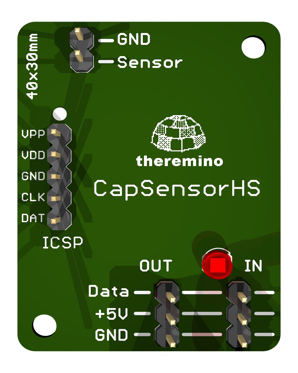
The sensor can be any conductive object, even non-regular shape, a simple copper or aluminium plate, an antenna, an electrician's wire or a sensor made with copper adhesive tape.
The sensor must be connected to pin marked “Sensor” a form CapSensor, with a non-shielded wire and not very long (from a few centimetres to a few tens of centimeters at most)
The pin marked “GND” can be let loose or connected to a metallic mass of reference which in some cases may stabilize the measure, reduce the noise and increase the maximum usable. The reference mass must be connected with a wire. The wire connection should be no longer than a few dozen centimeters. The mass should not be facing the sensor or too close to it because otherwise the sensor capacity would increase too and the range will be reduced.
The sensor surface can vary from a few centimeters to over a meter. With large sensors you get a range of several meters, small sensor range is reduced to a few centimeters.
The sensor and its connection wire must be placed away from metal parts and electronic circuits, that can be disturbed. Usually the distance to be observed is comparable to the desired operating range.
If you use more CapSensor simultaneously then their sensors must be distant from each other by a distance comparable to their radius of action. If you get too close, It may happen that influence each other. You can verify if you are rivetted, checking if their frequencies are identical (frequencies shall be read in the properties of the pins of the HAL program). To prevent two adjacent sensors influence you can apply a capacitor 15pF (NPO) between terminals GND and Sensor, on one of them (If there are only two), or on all odd sensors (If there are many)
Operation CapSensor

The operation is based on an initial measure called “calibration” that stores the value of sensor capabilities at rest.
Following the approach any conductive object, a hand or a metallic object, increases the ability of the sensor to a very small quantity proportional to the distance between sensor and object.
Using a low noise FET of an ADC to 24 bits of the slaves CapSensor type are able to accurately measure very small capacitance changes, even less than 1/1000th of a PicoFarad, and provide the software to fit a digital value very accurate and stable.
Measurement software, located in HAL program, taking into account the adjustment value, parasitic capacities and physical laws that bind areas, distances and electric capacity, make a very complex calculation that turns raw data into a distance value quite linear.
The CapSensor is less precise and less linear distance of a ultrasonic sensor but has a unique property, the gradual nature of the distance measure that cannot in any way “Skip” between two values.
The gradualness and the response speed of CapSensor are not obtainable with any other sensor. Only with CapSensor you can drive sounds and videos in more straightforward and enjoyable way.
The HS version is identical except for a small change in the firmware that produces a faster response when moving the hand quickly. This property is enjoyed by those who play the theremin.
Sharp IR distance sensors
These sensors using infrared rays, collimated into a very narrow beam with a lens and measure the distance between the sensor and the target with the method of triangulation.
For details see page: hardware/sensors/sharp-sensors

Ultrasonic distance sensors

For the precise measurement of time generated by this module ranging from some micro second to 30 Ms you have to use your pin type “Usound_sensor” available on all pins on the Master or on pin 9 of the modules “Servant”.
If you are using the Master, to change PIN you must disable the previous, before you configure another pin like Usound_sensor.
Pay attention to the order of the wires, What is different between the modules type “Srf05” and standard connectors of the system Theremino.
SRF05sensor: Signal GND + 5V Theremino: GND + 5V Signal
This module consumes only 4 mA, You can connect a large number in a system Theremino with power from USB.
We only tried the SRF05, but all sensors of the SR series, should be fine. Before you buy make sure have a universal interface, and not a particular interface, for example, the system “Grove”, or a serial or I2C. Also check that signals and voltages are the same as SRF05.
More info here:
Srf05: http://www.robot-italy.com/en/low-cost-ultrasonic-range-finder-1.html
SRF04: http://www.robot-italy.com/en/low-cost-ultrasonic-range-finder.html
– – – – – – –
A new sensor that is cheap, the HC-SR04
This sensor is located on eBay for under five dollars, shipping included, It has almost the same characteristics as those from 20 Euro.
We tested it and it goes worse than “Srf05”, is more unstable, bouncing between the right distance and maximum and does not 3 meters.
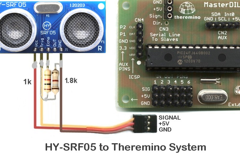
A further problem of HC-SR04 is that it has separate links TRIG and ECHO. Why you must link them together with a resistive divider to lower the output voltage from 5 Three volts to 3 volts, System Theremino. Then use the link only TRIG. (click on the image for a larger view)

This change with two resistors has been tested and works fine. Do not use resistors of value other than those listed. The relationship between the two resistors must be maintained and you shouldn't climb too much of resistance. (at most you could use 1.2 2.7 2.2 1.5 k and k and k or k) Here, too, many thanks Mauro for insisting in tests up to make it work.


We thank Mauro Rafaela for letting us know the HC-SR04 and goddess of application “radar”
A video of the first version: http://www.youtube.com/watch?v=Yw1YPpPC9Ww
A video of the ThereminoRadar version 1.2: http://www.youtube.com/watch?v=FsW4qwXvpB4
More information on the prototype of Mauro Robotics Blog: blogs/robotics and cnc
Download of TheremioRadar: downloads/automation * radar
– – – – – – –
Update of the 2021
The HC-SR04s work badly and there is already something to thank when they work, because many just don't work. Numerous companies copy them one from the other and every time they copy some component is wrong, so due to accumulated errors they hardly work anymore.
We therefore recommend using the HY-SRF05 instead (cheap too), connecting them according to the following scheme.
General characteristics for all sensors
Are measurable distances from 1 cm to over 4 Mt
Beam width approx 30..50 degrees.
The resolution of our firmware is about 0.1 mm but Ultrasonic sensors, even the best and the best environmental conditions, do not fall under the mm.
ATTENTION: The maximum distance is not always accessible. All ultrasonic distance sensors have a wide enough and that becomes easily fooled by obstacles and signal reflections. The actual accuracy depends on many factors and in some cases you can get totally wrong. This is not due to any defect of the modules of the system Theremino but to an inherent weakness in the ultrasonic detection method. To make precise measurements you should use infrared distance sensors (SHARP), or even better those with laser technology.
Reducing beam width
The amplitude of ultrasonic beam is approximately 60° (red curve), but can easily be reduced to 30° (green curve), with complete elimination of side lobes, with two tubes of soft material that protrude about 10 mm beyond the top of the sensors.


Original article and attenuation characteristics at:
http://www.robot-electronics.co.uk/htm/reducing_sidelobes_of_srf10.htm
Improve ultrasonic sensors
All ultrasonic sensors, even the best, every now and then they lose the signal. Sometimes the reflections create destructive interference and the measured distance suddenly jumps to a different measurement. This problem resembles radio signals, which in certain points fade to the point of lacking. And the solution we found is the same as the one used with WiFi, that is, double or triple the antennas.
Until now (early months of 2021) we were convinced that ultrasound could not be used for homework “delicate”, such as using the application Video Player to scroll a video back and forth, when a visitor approaches a painting on the wall. Then, when searching for a safe and reliable way to slow down COBOT when a human approaches, we tried to increase the number of sensors.
The result is remarkable, already with two sensors i “jumps” they almost completely disappear. And since the sensors cost a few Euros, three or even five can be used, thus obtaining a very high reliability and a perfectly stable signal.
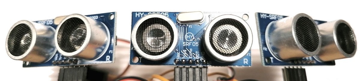
Use multiple sensors (and the firmware we wrote supports up to 17), it also allows you to position and direct them in order to enlarge the sensitive area. Visitors can therefore be heard even if they come from the sides, or even from behind as it can happen with ours COBOT.
With our firmware, even the poorest and most defective sensors can be resurrected (HC-SR04), which would otherwise be totally unreliable. We still recommend using cheap but better quality sensors, i.e. the HY-SRF05.
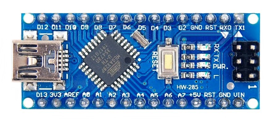
To connect many sensors you need a module with many pins, possibly cheap and small, basically an Arduino NANO (look for the ones with the CH340 that perform better).
The firmware we wrote is very nice, reads up to 17 Input pin for return echo signals. It achieves the highest accuracy and reliability by using a sophisticated mechanism of “interrupt on change” on all input pins and also manages to identify and correct defective samples.
The resulting single signal is the measurement in millimeters of the closest object.
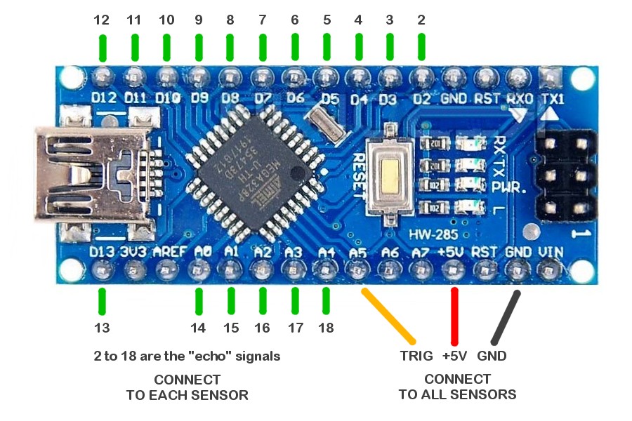
To make this system work you will need:
– Install the Theremino library in Arduino (if it isn't already there)
– Load the Theremino_USOUND.ino firmware with the Arduino editor
– Choose the PINs to use (FirstEchoPin e LastEchoPin) in the area “INITIALIZATIONS”
– Connect the Nano, choose the right COM port and program it.
– Open the ArduHAL application and check that it sees the PINs (possibly read This page)
– Set the first PIN (Pin zero) come Gen_in_float
Then double clicking on the first Pin, the small oscilloscope of the HAL opens and you can verify that the system is working well, moving a hand in front of the sensors.
DOWNLOAD THE FIRMWARE AND SOFTWARE
The ZIP file to download contains the firmware for the Arduino Nano, the ArduHAL application and the Theremino library to communicate the Arduino Nano with the ArduHAL application via USB. Read the explanations for ArduHAL in This page.
Download di Theremino USOUND
Theremino_USOUND.zip
For all Windows systems to 32 and 64 bit. For Raspberry Pi, Linux, Android and OSX, read the installation notes.
Capacitive keypads and proximity sensors


CapTouch type buttons link to “PIN” System Theremino with an electric wire or with a lead on a printed circuit board, as PinType you choose “Cap_8”, or “Cap_16”. For more information please refer to the datasheet for the ThereminoMaster module and documentation of application ThereminoHAL.
Each key consists of a plate of conductive material. Platelets are normally sized to be touched with a finger but can also be very small, very large and any how, for example,, the keys of a piano or the petals of a flower.
If you use a printed circuit plate keep the copper on the upper side, It covers everything with a sheet of paper printed with the design of the keys and finally with a thin sheet of transparent plastic to get a surface waterproof and easy to clean.
Cursors “slider” you make up with form “multi-triangular” that is sensitive to movements in the vertical direction but with a very low sensitivity to movements in lateral direction (the triangular shape is our multi-improvement over solutions Microchip that are more complex, little linear, and answered to the movements less like a true “slider”)
Controls that Act on two axes, like a mouse, require four plates “multi-triangular” riots in four directions and special software to compose the four values in the two axes X/Y and Z axis representing the height.
CapTouch technology can also replace the classics “proximity sensors” widely used in industrial controls but with less cost, a hot spot of any shape and adjustable sensitivity.
– work through one layer of paper or plastics often many millimeters
– wires can be quite long and must not be screened
– the buttons do not suffer from radio
– they have a fast response (few milliseconds)
– do not produce Ricochets
– costing much less mechanical buttons
– do not suffer from moisture
– a slave of type “Servant” It can read eight directly (one for pin)
– crossover techniques you can read up to 36 keys with only one slave module type “Servant”
Capacitive proximity sensors for small distances
These sensors use capacitive technology, like previous CapTouch and CapSensor, but they have a functioning of type “On or off”.
Sensors offered here previously were giving problems. MTCH101 chip not working according to the declared characteristics in its data sheet for which we have abandoned.
Therefore, it is recommended that you use in its place the TTP223 that can be found for a few euros on eBay and Amazon.
Supply voltage
The 5 Volts coming from USB are not very stable and this sensor may malfunction (take sometimes alone). Also supplying it with 5 Volts, the output would be 5 Volts and would send the security Master. Then you should lower the output signal from 5 volts to 3.3 volts, with a divider 2.2 k in series with the signal and then a resistor from 4.7 k to ground. Why we recommend feed this sensor with the 3.3 volts stabilized by Master.
Features
- Detection of metal surfaces at distances up to ten centimeters. Increasing the area of sensitive parts you get increased distance of revelation (about one centimeter away for every square centimetre of area).
- Must be connected to a standard Pin, configured as DigIn.
- Must be supplied with stabilized voltage, so it is good to link it to 3.3 Volt available on some Master Pin.
Advantages of this solution
- You can connect with three wires to the pins and the three strands can be very long, even tens of meters.
- Connect to digital Pin (DigIn) and then all the pins are valid (Twelve Master and ten on the slaves Servant)
- Cheaper than CapSensor.
Light sensors
Many types of light sensors, photodiodes and photoresistors are easily connected to standard input of the system Theremino.
For details see page: hardware/sensors/light-sensors


Encoders
The encoder reads the angular position of a PIN, as the potentiometers, but the number of rounds is unlimited.
There are similar to small potentiometers encoder (the best known are the KY-040 of the following images). These models are mechanical and provide 18, 20 or 24 pulses per revolution, Depending on the constructor. Firmware obtained from these pulses 72, 80 or 96 angular positions per revolution.
Other encoder, magnetic or optical, they have a very high number of pulses per revolution (600, 2400 and beyond). With them you have to limit the rotation speed in order not to exceed the maximum speed allowed by the Pin-type Encoders (about 10 KHz and even less if the micro-controller is overloaded).


The two phases, herein with CLK and DT, linking to a pair of pins configured as Encoder_A and Encoder_B. Swapping the two wires you reverse the direction of rotation.

Mechanical encoders can easily generate extra or missing pulse, because the bounce of contacts. To improve the functioning of the encoders KY-040 shown in the pictures, We recommend that you:
- Replace the two SMD resistors from 10 Kohm, with two capacitors from 100 nF
- Configure the two pins as Encoder_A_Pu and Encoder_B_Pu
- Do not connect the encoder to the 5 Volts, or to 3.3 Volts, Master Pin
- Connect the Terminal “+” to “GND” (to ground the two capacitors)
This solution has the advantage of not having to worry about which supply voltage supply the encoder.
Those who want to use the original schema with two 10 k resistors, should take care to provide the 3.3 Volts (not the 5 Volts) to the Terminal “+” the encoder. Should add two capacitors from 100 nF. And finally should configure the pins like Encoder_A and Encoder_B (without “Pu”).
Optical or magnetic encoders
Optical or magnetic encoders have generally a very high number of steps per revolution. You must therefore plan carefully mechanics, so as not to exceed the limit of a few KHz of Pin type “Encoder”.


For applications requiring high speed and accuracy you need to use adapter such as the one shown in the image. With these adapters the maximum counting frequency rises to approximately 1 MHz, But even the cost goes up in proportion. Commercial adapters cost about 50 Euro for each axis. Instead with a Theremino Master, the cost per axle is approximately 2 Euro.
Please note that many optical encoders should be fed to 5 Volt and their output signals range from 0 to 5 Volts. Then exceed the maximum voltage of the inputs of the Master. Overcoming the 3.3 Volt Master does not harm but lose communication with USB ’ and press “You acknowledge” to restart them. You can directly connect the signals only if the outputs of ’ are Open Collector encoder. Otherwise there are the following three solutions:
1) Interposes a 100 k resistor in series with each signal (close to the Master) and you set the inputs without pull-up (Encoder_a without _ pu).
2) Interposes a diode 1N4148 on each signal wire, with the collar towards the ’ encoder and set the inputs with pull-up (Encoder_a_pu).
3) You use the inputs 7 and 8, tolerating signals from 5 Volts. This is the cleanest solution, also on the same five-pin connector are available also the mass (GND), the power supply (+5V) and an auxiliary input (9), that can be used to connect the signal “Index” the encoder.
Usually the encoders have the wires with standardized colors then, If you use the inputs 7, 8 and 9, You should connect them as in the following table:
GND ---- Black
7 ------ Green (A)
8 ------ White (B)
9 ------ Yellow (Index)
+5V ---- Red
Read the signal of the encoder
All inputs Master count (Encoder_a, Encoder_a_pu, Counter, Counter_pu, Fast_counter and Fast_counter_pu) generate an output value between zero and 65535 (16 bits total). When you exceed the value 65535 starting again from scratch and when it drops below zero it starts from 65535. This mechanism allows many applications to read the value asynchronously. Applications can be undertaken to do and are not required to register any change in the value. Just read the value periodically, at least sometimes every second, to never miss the step.
The application Theremino Counter Reader shows how to correctly read the encoders and counters.

Simple projects can use Theremino CounterReader, to read an encoder from a slot and write the value to another, but major applications should use the “CounterReader”. In this way would have access to the function ReadValue, to be called periodically and Reset function that resets the value at any time (What is done by the button “Zero Set” the Counter Reader).
From version 1.2 onwards it is possible to use encoders with maximum count of 65535, 4095 or 255 pulses. The ability to set it to 4095 pulses allows to read the magnetic encoders of the Feetech servos in order to obtain a virtually unlimited multi-turn space. See also the Theremino_Modbus application and the page dedicated to Feetech servos (to be published in December of 2020).
Download di Theremino CounterReader V1.2
Theremino_CounterReader V1.2_WithSources
For all Windows systems to 32 and 64 bit. For Raspberry Pi, Linux, Android and OSX, read the installation notes.
Potentiometers
All the transducers that behave like a potentiometer, can be connected to the pins of the system Theremino and read immediately. For the “Pintype”, you choose Adc8 or Adc16 (Adc16 = greater accuracy).


Here you will find sample (with great prices) of various types of sensors and classic knobs, they behave like potentiometers:
www.sparkfun.com_Membrane_Potentiometers
www.sparkfun.com_Flex_Sensors
![]()
Even linear transducers can be connected directly. (check potentiometers from 1 k to 100 k, If in doubt send the DataSheet before buying)
– – – – – – –
There are many perfect analog Joysticks to the system Theremino.

The model of this picture, it is easy to connect and also has a push button. It can be easily found on eBay for less than 5 Euro (Search: Analogue Joystick Controller).


There are also much smaller analog joysticks (for the playstation) or very large (with four side potentiometers). Please note that it may be difficult to mount them mechanically and connect the wires to the potentiometers. Always check that they are analog.
– – – – – – – –
Potentiometers and transducers must be powered with voltage 3.3 volts. This to not send voltage over 3, three volts to the input pins and to get the right range from zero to maximum, reading them with the pins configured as Adc16.
To get the 3.3 Volt may count a resistor between + 5V and potentiometer, calculated on the basis of the resistance value of the potentiometer to obtain 3.3 volts. This method, however, would have two flaws: the first is that the 5 volts derived from USB port is quite loud and can also change of half a volt from one computer to another. The second flaw is that the actual resistance value of the potentiometer is often quite different from the theoretical to the actual voltage will not 3.3 Volt exact and you don't succeed in arriving at the most or it will come before the end of the stroke. To avoid these problems would be better power the voltage droop potentiometer 3.3 volts, see for example the one shown at the end of this document.
To power the potentiometers you should connect the two ends of the potentiometer to connections 3.3 Volt socket and GND ICSP-AUXpins and the Central Server to input PIN connection SIG, as shown in the following pictures:

This image refers to the connection of the “ribbons” (used in the ThereminCello) but the principle is valid for all sensors, acting as a potentiometer.
![]()
This image refers to the connection of linear transducers, but the principle is valid for all sensors, acting as a potentiometer.
A CAUTION: Make sure that the potentiometer's Central (2), is connected to a pole “SIG”, one of the Theremino PIN. If you connect the potentiometer Central to “GND” or to “3,3V”, the potentiometer can warm and ruin!!!

Instead the two extremes of the potentiometer (1) and (3), that bring the power (+3.3Volts) and (GND), can be switched between themselves without damage. Swap (1) with (3) can serve, to reverse the measures relative to the direction of motion.
Many potentiometers can be connected in parallel to the poles 3.3 and GND. But each potentiometer must have its central strand (2) separate and attached to a pole “SIG” separated.
The inner resistance of the potentiometer is not critical. All manufacturers of linear transducers using values from 1 k to 100 k, so should all go well. (even less than 1 k and above 100 k might work, but in the first case it would consume too much current and the latter would have little linearity and increased noise picked up by the wire)
A potentiometer might also be used as a variable resistor, If you're using it with only two terminals (freeing one of the extremes). This type of connection acts as simply simplicity, only two wires and no power. As disadvantage though, to use exactly the whole range of values (normally from 0 to 1000), You should use a potentiometer from 50 Kohm precise. To where you normally will use a potentiometer from 47 Kohm, that produces values between 0 and 940, with some room before best and finally you will have to fix the software.
Variable resistors
Many transducers act like variable resistors, such as Photo-resistors and variable resistors with temperature (PTC or NTC)


The variable resistors are connected between ground and signal (the two extremes of the input PIN) allowing the Central wire carrying the power supply. How to Pin type you choose Res_8 or Res_16.
To produce a good hike with PIN configured as Res8 or Res16, the value of the resistor should vary from very low values about 50 kohm.
Connect the Force Sensitive Resistors


It's not about sensors to make scales but, for example,, to feel the pressure in a ThereminCello, by placing them under the potentiometer of the note (usually a Ribbon).

These sensors typically have a very high resistance (about 1 Mega Ohm) When they are pressed and their resistance drops off logarithmically, increasing the pressure, up to a few hundred ohms, When pressed with strength (about 1 Kg)
Their resistance is perfect to be able to connect directly to our PIN. Connect to each SIGNAL and GND, leaving unused the 5V. And finally, you configure the PIN as Res16.
Thanks to its logarithmic response responding to pressure in a natural and accurate.
Connect the variable resistors as potentiometers
If you are unable to have a good hike can transform a variable resistor in a potentiometer, with the addition of a fixed resistor, as shown in the following image:

Depending on the excursion of the variable resistor, You must use a fixed resistor value. Try changing the fixed resistor value and check with the application Viewer HAL, until you get the desired values with the excursion.
As Vcc must be used 3.3 Volts stabilized and voltage V must be connected to the GND signal to an input PIN configured as Adc8 or Adc16.
In practice this configuration gets a potentiometer, then see the previous section for details of connection of the potentiometer.
Liquid sensor into pipes
To identify the presence of liquid in transparent plastic tubes 1.6 mm to 6.3 mm in diameter OPB350 sensors are comfy, inexpensive and can be easily connected to the system Theremino.
To read the value you set the input as “ADC” so you have a proportional detection. A proportional value makes it possible to discriminate the presence of liquid but also measure its turbidity and the presence of solid particles in the stream.
In special cases, with liquids very turbid or very transparent, If the measured value is very low or very high, you could increase the value of the resistor from 10 k up to 100 k or lower it down to 1 k.
If the ambient light is not too strong it could operate the led with lower current of 18 but standard and save power if you use many of these sensors. With a resistor from 3300 ohm resistor, for example,, the current would be about 1 but you could compensate for the loss of signal by raising the resistor from 10 k up to 100 k or even 220k.


Since the output signal can exceed 3.3 Volts Input system accepted by pin Theremino, consider adding a resistor in series with the signal from 33k (Yellow wire) If anyone has time and inclination might change the PCB, move R2 on the manifold, change it from 10 at 33k and pick up the signal from the collector, This way you would eliminate the additional 33k.
These sensors are available in various models with prices from 4 to 10 euros at Farnell,
go to the site http://it.farnell.com and search for OPB350
Always at Farnell is available the data sheet with full technical data.
http://www.farnell.com/datasheets/4603.pdf
–
Adapter to PCB or veroboard OPB350
Following the track of the images below to create an adapter on a Breadboard or plate cutout on a printed circuit.
The first two images are for model APB350 Strait the following two are for model largo. The Eagle can complete projects download from here: AdapterOPB350_EagleProjects


PH and ORP sensors (Oxidation/Reduction Potential)
To measure the PH we recommend these excellent adapters built by Phidgets that cost about 25 Euro.

Here are the key facts: www.phidgets.com/products.php?product_id = 1130_0
In the user-guide you will find all the electrical characteristics, the formulas for the calibration and advice on which use electrodes www.phidgets.com/docs/1130_User_Guide
Since this sensor provides an output from 0 to 5 volts and that the inputs of the system Theremino using a standard 0 to 3.3 Volts must be added, on the connection cable, a resistive divider from 10 k in series with the signal and 22K to ground.
            White---------- 10K --@---------- White
                                     |
                                    22K
                                     |
PH SENSOR Red ----------------------------- Red MASTER
                                     |
              Nero ------------------@---------- Black
As a workaround you could replace a resistor on the module Phidgets. If you don't know how to do this please email us and we will help you with detailed drawings.
Magnetic sensors
To measure the magnetic field A1301 and A1302 sensors are recommended products from Allegro Microsystems, the 1301 is more sensitive, costs less, and will get better in almost all applications. See catalog Farnell: http://it.farnell.com and try A1301/A1302. The manufacturer instructs you to feed them from 4.5 to 6 Volt based on the internal regulator and an operation ratio-metric but after many trials we found that with a stabilized voltage outside of 3.3 volts are achieved better stability and noise, as well as a resting position exactly half of the field of ADC values. Here are the features for the two models
SENSOR Sensitivity Saturation Power supply Price approx
         ( MV/Gauss )   ( Gauss )    ( mA )        1/10 PCs
-----------------------------------------------------------------
A1301    1.65           +/- 1000     11 mA         1.5/1.2 Euro A1302    0.87           +/- 1900     11 mA         1.7/1.3 Euro

–
These sensors are available in surface mount version ( SMD ) or with normal legs ( SIP ), Here are the containers for the two versions. Please note that the order of the links is different depending on the version ( SMD or SIP ) and that in both cases is different than the standard system Theremino.
——————————————
——————————————
——————————————
——————————————
—————————————-
———————————————————————————— 
For maximum sensitivity and minimal noise is good to feed these sensors with controller from 3.3 Volt visible in this image and shown at the end of this document. This picture also shows how to reverse the wires to fit the sequence of links to that SIP type sensor. This example doesn't use the connectors and the regulator has been welded along the cable getting a small, stout wiring. Finally a tube Thermo-shrinking will complete the wiring, by isolating the regulator and increasing the strength of the connections.
Sensors of “Breath” and pressure
To reveal weak pressure differences could use electret microphone connected to this control amplifier, the output can be directly connected to any Theremino pin configured as ADC. Use an electret microphone to two terminals (three-Terminal ones) and make sure you connect the part that makes even the carcass to the ground connection (In-) This preamp is designed to connect it to an underground pipe that acts as a detector of steps. The tube is tightly connected to the microphone and sensitivity is very high so as to reveal small movements of the layer of Earth covering the pipe. If you want to use this detector with less sensitivity, for example, as revealed by puff, It is good to lower C2 and C4 in 1uF and raise R2 and R4 to 100 k. If the sensitivity is still too much raise further R2 and R4. With these changes, it also enhances the initial settling time that with the original values is very long (about a minute).


AC current sensors
With AC sensors can measure the current drawn by an appliance, by a motor or by an entire electrical system. By measuring with an ADC channel at full frame repetition is averaging of squares (RMS — “Root Mean Square”) and finally multiplying by 220 (the mains voltage), with a program on the PC, you get a precise measurement of the power with the resolution of a watt. We recommend the sensor (current transformer) model 3110 the CR-Magnetics that costs roughly around 10 Euro, is very accurate and can measure up to 16 Kwatt (75 Ampere in 220 volts). The sensor 3110 allows you to make secure measures because it has excellent insulation and is certified CE and ISO (certifications are available on request)

Model 3110 specifications
----------------------------------
Max primary current:  75Aac Frequency:            50/60 Hz Secondary turns:      3000
DC resistance:        460 Ohms Precision:            1%
Isolation continuous: 1KV Isolation max:        5KV Wire lead:            AWG 18
A diode bridge makes positive both half-waves making the calculations to do in software, In addition this method eliminates the need to calibrate the zero point. You don't have to worry about the fall on diodes and its variation with temperature because the current transformer is a nearly perfect current source. Depending on the desired full scale load resistor value should be chosen according to table:
Full scaleWatts |
Full scaleAmperes AC |
Load resistor for a full scale of approximately 3 volts (leaving a small margin of 3.3 V) |
Measurement resolutionWatts |
| 16000 | 72.8 | 180 | 1 |
| 8000 | 36.4 | 360 | 0.5 |
| 4000 | 18.2 | 720 | 0.2 |
| 2000 | 9.1 | 1500 | 0.1 |
| 1000 | 4.5 | 3000 | 0.05 |
Voltage and current sensors – Simple version
Tensions related to mass can be measured with a simple resistive divider and a conventional ADC. Standard connectors of InOut using only the two extreme pin, Mass and Signal, While the center pin that bears +5 is not connected.
          (+) ------- R1 ---@--------- White(White)
                            |                          Theremino Input voltage R2      --- Red(Red)      standard
                            |                          Inout Pin
          (-) --------------@--------- Black(Black)
Between signal and ground connecting a resistor which we call R2, instead between the positive terminal of the voltage to be measured and the signal pins connecting a resistor which we call R1.
Voltages from 0 to +3.3 V, resolution. 50 micro Volts (R1 = 10 k - R2 does not present)
Voltages from 0 to +10 V, resolution. 200 micro Volts (R1 = 100 k - R2 = 33k)
Voltages from 0 to 100 V, resolution. 2 Milli Volts (R1 = 1 Mega - R2 = 33k)
Voltages from 0 to 1 KV, resolution. 20 Milli Volts (R1 = 100 Mega - R2 = 330k)
Voltages from 0 to 10 KV, resolution. 200 Milli Volts (R1 = 1000 Mega - R2 = 330k)
Devices for high voltages: To measure voltages exceeding 100 Volt safely the resistor R1 must be able to withstand twice the voltage you intend to measure. Rather than a single resistor is better to use a string of several resistors in series from 10 Mega or 82 Mega (Farnell 1469973 / 2073866 / 9236503) In this way you spend much less than buying high-voltage resistors and you get extra security due to the total length of the string, that helps physically HV and prevents Arc Flash.
To measure high voltages see also recommendations of the page: /blogs/gamma-spectrometry/hardware-tests
The current is 1uA for flow rate 3.3 Volts, 100UA for flow rates 10 and 100 Volts and brightness for 1000 and 10000 Volts, If this current was excessive then it would be better to use the differential sensor next chapter working normally with 100nA currents and can be adapted to work with smaller currents.
————————–
Currents related to mass can be measured with two resistors and a conventional ADC. Standard connectors of InOut using only the two extreme pin, Mass and Signal, While the pin English tv channel that bears +5 is not connected.
          (+) ------@--- 10K ------ White(White)
                    |                               Theremino Input voltage R1           --- Red(Red)      standard
                    |                               Inout Pin
          (-) ------@-------------- Black(Black)
Between the input (positive) the current to be measured and connect a resistor which we call R1, a second resistor from 10 K Ohms is used to limit the current to the Pin of InOut and protects it against every kind of mistake.
Currents from 0 to 100 UA, resolution 2 NA (R1 = 33k)
Currents from 0 to 1 mA, resolution 20 NA (R1 = 3300 ohm resistor)
Currents from 0 to 10 mA, resolution 200 NA (R1 = 330 ohm resistor)
Currents from 0 to 100 mA, resolution 2 UA (R1 = 33 ohm resistor / 1 Watts)
Currents from 0 to 1 A, resolution 20 UA (R1 = 3.3 ohm resistor / 10 Watts)
With these simple circuits when measuring the maximum current of each course there is a voltage drop 3.3 Volts which can distort some types of measures, If this fall is too large then it is better to use the differential sensor of the next chapter, It normally has a fall less than 150mV and can be adapted to also lower falls.
Voltage and current sensors – Differential version
This circuit is a “Jolly”. Can measure very small voltage differences (or very large) even with strong common mode voltage.
Connect CN2 – OUT with a standard cable to a Pin of InOut system Theremino configured as ADC (Adc16 for maximum precision)


With this scheme the circuit tolerates common-mode voltages up to +/- 33 Volts and with the replacement of R9 gets the following voltage range:
Voltages from -10 MV to +10 MV with a resolution of 0.3 micro Volts (R9 = 1.5 Mega)
Voltages from -15 MV to +15 MV with a resolution of 0.5 micro Volts (R9 = 1Mega)
Voltages from -30 MV to +30 MV with a resolution of 1 micro Volts (R9 = 470k)
Voltages from -100 MV to +100 MV with a resolution of 3 micro Volts (R9 = 150 k)
Voltages from -150 MV to +150 MV with a resolution of 5 micro Volts (R9 = 100 k)
Voltages from -300 MV to +300 MV with a resolution of 10 micro Volts (R9 = 47k)
Voltages from -1 V a +1 V with a resolution of 30 micro Volts (R9 = 15 k)
Voltages from -1.5 V a +1.5 V with a resolution of 50 micro Volts (R9 = 10 k)
Voltages from -3 V a +3 V with a resolution of 100 micro Volts (R9 = 0)
Choose a perfect compromise between the characteristics
If you overdo it with the full scale It degrades the accuracy and resolution.
If you overdo it with the common way tolerable will worsen stability to changes in temperature and ease of adjustment (adjusting trimmer).
So it is good minimize common mode voltages (by making the appropriate ground connections and ground) and don't overdo it with the common way bearable.
Minimize common mode voltages
No ground connection, in some cases, especially with laptops that don't have the Earth on the plug of the 220 Volts, could develop tensions between the PC and the setting even of hundreds of volts. In these cases you should use a range bearing 330 Common mode Volt, significantly worsening stability.
Instead, If the mass of the PC is grounded, You can use dishes that bear only 3.3 Common mode volts and you get an improvement of 10 times of temperature stability and ease of adjustment.
If your PC is connected to the Earth through the power outlet are okay (check and make sure the electrical system is grounded as by law)
Otherwise you can connect a wire to the ground of the electrical system, beginning of the Master in a rugged point (the best place is where there is a large ground plane close to the USB connector). You could also connect the ground of the electrical system to the point of any of the PIN GND of the Master or a Slave or even the preamp input GND. Though they are all sensitive points and it is not advisable to use them, better the robust USB mass.
In all cases it is always good to add a resistor from 100 ohm resistor (1/4 Watts), in series to the wire that goes to ground. This resistor prevents produce rings of masses, with milder forms artifacts and also acts as a fuse in the event of serious errors in links.
ATTENTION: USUALLY THE SYSTEM THEREMINO TOLERATE ANY MISTAKES WITHOUT DAMAGE BUT THIS’ A SPECIAL CASE – WE'RE BINDING THE GROUND OF THE ELECTRICAL SYSTEM THAT’ BIG, BAD – YOU MUST CONNECT THE GROUND SIDE OF THE PC OR THE USB AND NOT, For example,, THE MASS OF A SENSOR OR A MASTER PIN – BEFORE POWERING UP ALL CONNECTIONS MUST BE COMPLETED AND CHECKED – JUST DO SOMETHING WRONG AND GIVE A SCINTILLONE IN THE WRONG SPOT TO FRY EVERYTHING!!!
Reduce the common way tolerable to +/- 3.3 Volts
Replacing R3, R4, R5 and R6 with resistors 10 Mohm and the two trimmers from 470 Kohm, you get the following voltage range:
Voltages from -10 MV to +10 MV with a resolution of 0.3 micro Volts (R9 = 150 k)
Voltages from -15 MV to +15 MV with a resolution of 0.5 micro Volts (R9 = 100 k)
Voltages from -30 MV to +30 MV with a resolution of 1 micro Volts (R9 = 47k)
Voltages from -100 MV to +100 MV with a resolution of 3 micro Volts (R9 = 15 k)
Voltages from -150 MV to +150 MV with a resolution of 5 micro Volts (R9 = 10 k)
Voltages from -300 MV to +300 MV with a resolution of 10 micro Volts (R9 = 4.7 k)
Voltages from -1 V a +1 V with a resolution of 30 micro Volts (R9 = 1.5 k)
Voltages from -1.5 V a +1.5 V with a resolution of 50 micro Volts (R9 = 1 k)
Voltages from -0.3 V a +0.3 V with a resolution of 10 micro Volts (R9 = 0 ohm resistor)
Increase the common way tolerable to +/- 300 Volts
Replacing R1 and R2 with resistors 100 Mega Ohm (R3, R4, R5 and R6 = 1 Mega and trimmer = 47k, as shown in the diagram), you get the following voltage range:
Voltages from -1.5 V a +1.5 V with a resolution of 50 micro Volts (R9 = 100 k)
Voltages from -15 V a +15 V with a resolution of 500 micro Volts (R9 = 10 k)
Voltages from -100 V a +100 V with a resolution of 3 Milli Volts (R9 = 1 k)
Voltages from -300 V a +300 V with a resolution of 10 Milli Volts (R9 = 0)
Increase the common way tolerable to +/- 3000 Volts
Replacing R1 and R2 with resistors 1 Gig Ohm (R3, R4, R5 and R6 = 1 Mega and trimmer = 47k, as shown in the diagram), you get the following voltage range:
Voltages from -1.5 V a +1.5 V with a resolution of 50 micro Volts (R9 = 1Mega)
Voltages from -15 V a +15 V with a resolution of 500 micro Volts (R9 = 100 k)
Voltages from -150 V a +150 V with a resolution of 5 Milli Volts (R9 = 10 k)
Voltages from -1000 V a +1000 V with a resolution of 30 Milli Volts (R9 = 1 k)
Voltages from -3000 V a +3000 V with a resolution of 100 Milli Volts (R9 = 0)
Increase the common way tolerable to +/- 30000 Volts
Replacing R1 and R2 with resistors 1 Gig Ohm, R3, R4, R5 and R6 with 100 K Ohm and the trimmer with 4.7k, you get the following voltage range:
Voltages from -15 V a +15 V with a resolution of 500 micro Volts (R9 = 1Mega)
Voltages from -150 V a +150 V with a resolution of 5 Milli Volts (R9 = 100 k)
Voltages from -1500 V a +1500 V with a resolution of 50 Milli Volts (R9 = 10 k)
Voltages from -10000 V a +10000 V with a resolution of 300 Milli Volts (R9 = 1 k)
Voltages from -30000 V a +30000 V with a resolution of 1 Volts (R9 = 0)
Devices for high voltages
If the input voltage exceeds 150 Volts, It must be ensured that R1 and R2 they can handle it.. Replace R1 and R2 with external resistors for high voltage, composed of many resistors in series, from 10 Mega or 82 Mega (Farnell 1469973 / 2073866 / 9236503). These resistors are cheaper (expensive and difficult to find) high-voltage resistors and using more resistors in series you get extra security. The total length of the string of resistors dismisses physically HV and prevents Arc Flash.
Increasing the value of R1 and R2 up to 1 Gig Ohm (with external resistors in series) You can measure voltages up to +/- 30000 Volts, in equally large common-mode voltages.
Increase the value of R1 and R2 It can also be used to further reduce the input current with 10 Mega Ohm standard is 100 NA for every measured.
Why don't we have provided protection diodes? Because they are already in operation and add unresolved would increase reliability. Don't be put off by the high voltages. If the input resistors are of high value, the current is low and it all fits smoothly. Of course you should know what you're doing and make no mistakes.
Measure the current
Not related to mass can be measured with an appropriate resistor value, Depending on the desired full scale. Starting from the basic version (from-150mV at + 150mV with all values as shown in the diagram) and by adding a resistor (called R0), between + and-, you will get the following courses:
Currents from -1.5 but to +1.5 but up to 1200 x. by 50 Nano Amps (R0 = 100 Ohm)
Currents from -15 but to +15 but up to 1200 x. by 500 Nano Amps (R0 = 10 Ohm)
Currents from -150 but to +150 but up to 1200 x. by 5 micro amps (R0 = 1 Ohm)
Currents-1.5 A at +1.5 At up to 1200 x. by 50 micro amps (R0 = 0.1 Ohm)
———————–
Calculation formulas
The values listed in the tables are approximate and are used to determine roughly the scale. You can get more precision simulations LTSpice or the following formulas:
Formulas
Voltage gain = (R3 / R1) * (1 + 2 * R9 / R8)
Maximum common mode voltage = 3.3 * R1 / R3
Maximum voltage differential = 3.3 / Voltage gain
Constraints
VoutMax = 3.3 Volts
VoutMIn = 0
R1 = R2
R3 = R4 = R5 = R6 (and selected to be greater than R3 R4)
Trimmers = about 5% of R3
———————–
This ZIP file contains the full Eagle PCB project, images, the schemas, the Assembly plans and simulations LTSpice: Sensor_DiffMeter
For simulations LTSpice download the libraries from this page:
https://www.theremino.com/downloads/uncategorized#ltspice
Current sensor
This simple circuit converts an ADC input of the Master module, in a high-side current sensor. One of the possible uses of this sensor is measuring the supply current of servomotors (the classics “servant” for model airplanes) and use this information to limit the mechanical torque that applies to output pin.
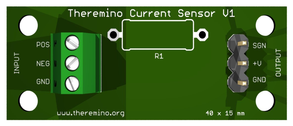
The feature that differentiates this circuit from others is the ability to measure the positive supply current, any device that works with voltages up to 28 volts (25 for not working right at the edge).
The current to be measured must be applied to the poles 1 and 2 INPUT connector. Basically you cut the positive power wire and link them to the pole 1, and continuing from the trade 2 you go to the powered device.
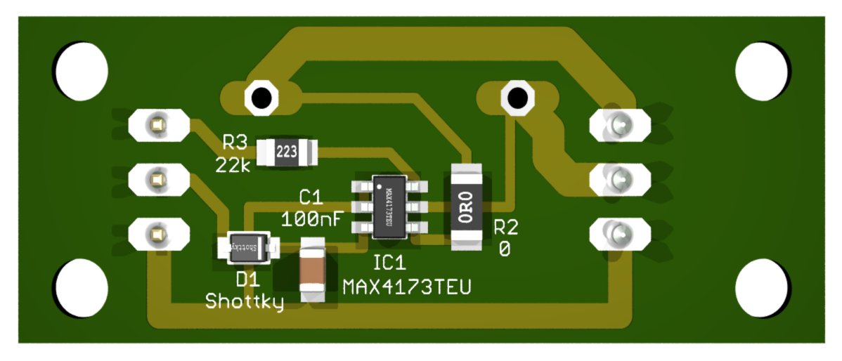
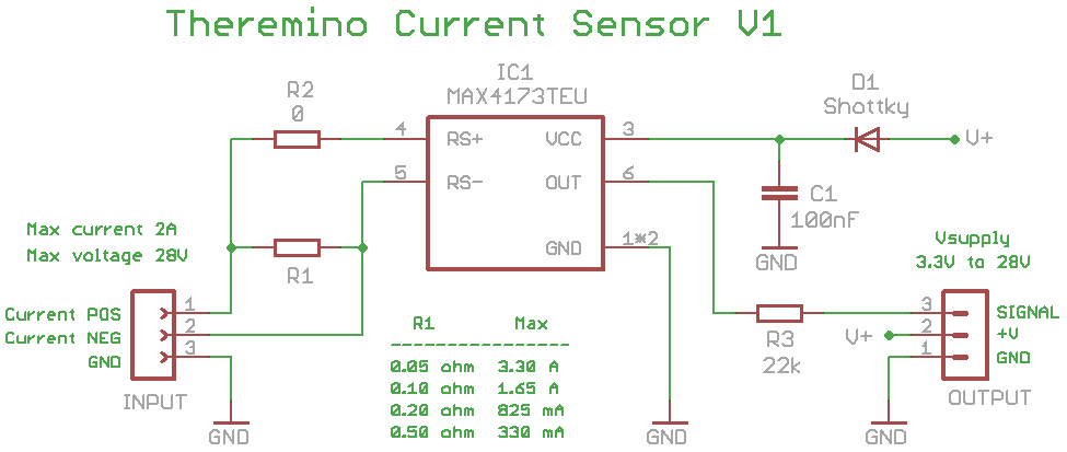
Replacing the resistor R1, It must be from 1 or 2 Watts and about 10 mm, You can get various measurement ranges, as indicated in the diagram.
You can also get other intermediate flow rates depending on the resistor you have available. If you have, for example,, of resistors 0.5 ohm resistor, using one you get 330 but full scale. But sealing a second parallel (next), you would get 660 mA. And sealing a third would 990 mA.
If you plan to exceed the maximum current rating, we recommend replacing R2 with a resistor of 100 ohm resistor. This protects the inputs even if you far exceed the maximum flow rate. Of course, beyond the maximum flow rate, you won't get any useful measurements, But at least the IC doesn't break. Also pay attention that, If the maximum flow rate is exceeded for a long time, resistor R1 may heat up and eventually even burn out.
You can build this sensor following the project Eagle that you download with This file. Or it can be purchased on the website Store-ino.
Resistance and capacitance sensors
Resistance from 0 to Res_16Capacità input can be measured with an ordinary 50Kohm tiny, in the order of one-thousandth of a pF can be measured with the slaves CapSensor. Take into account that the system Theremino is made to measure resistance values and skills that change over time and not to measure the components of which it is much better to use a normal tester that has many advantages and does not require calibration.
Humidity sensors
Humidity sensors (and temperature) they're all on the page of meteorological sensors
https://www.theremino.com/hardware/inputs/meteorology-sensors#hih4000
Thermocouple temperature sensors
The temperature sensors (and humidity) they're all on the page of meteorological sensors:
https://www.theremino.com/hardware/inputs/meteorology-sensors#thermocouples
Temperature sensors
The temperature sensors (and humidity) they're all on the page of meteorological sensors:
https://www.theremino.com/hardware/inputs/meteorology-sensors#ambient
Load cells
The load cells can be connected to Pin type ADC, through a form Differential Meter, but give a very low output signal, so it is difficult to obtain a good stability.
To test the load cells serves application HAL and is also useful to the application “Balance” that you download from this page: https://www.theremino.com/downloads/automation#balance
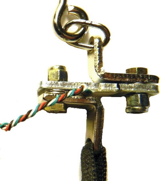
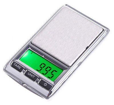
Modify precision scales and connect them to the ADC24 module
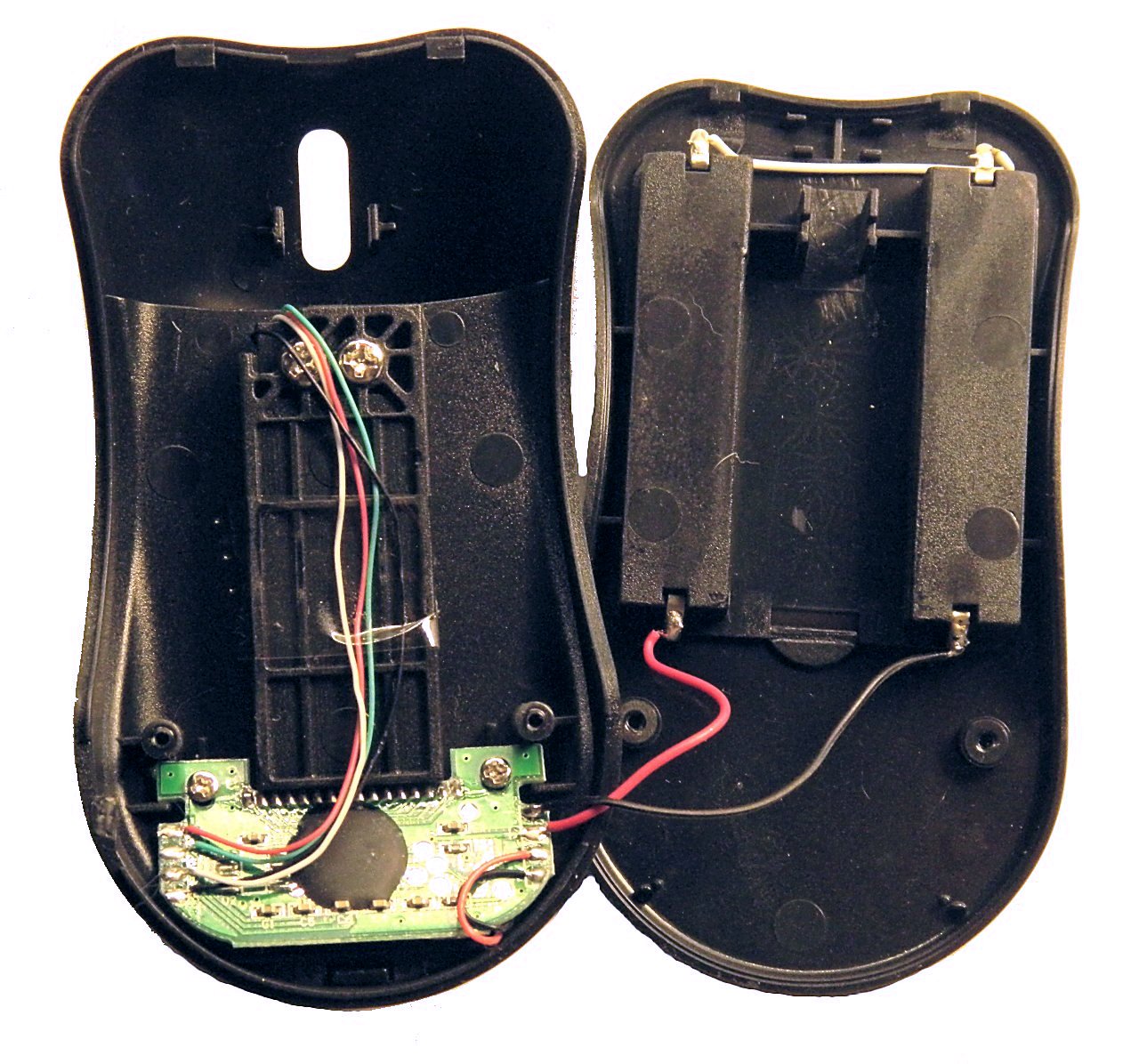
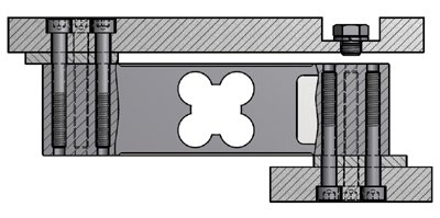
Some precision scales, You can buy on eBay for a few euros, contain very precise load cells. The trapezium mechanism of these cells makes vertical the weight force wherever they load positions. In this way the measurement is independent of the position and shape of the object to be measured.
If you have the new ADC modules 24 the connections are simple and very good performance. A form Theremino Adc24 It can read up to 8 scales, one hundred times per second. If the mechanics are adequate can achieve resolutions up to milligrams and beyond. The load cells are connected directly, without adapters and no potentiometers to calibrate.
This document explains how to connect the load cells system Theremino.
In this new version is explained how to change the precision scales and what are the best to buy (from page 9 onwards)
https://www.theremino.com/files/Connecting_LoadCells_V2_ENG.pdf
https://www.theremino.com/files/Connecting_LoadCells_V2_ITA.pdf
Adapters, voltage regulators, flow restrictors
Some sensors and actuators require limited current regulated power supply or. In some cases we must also adapt the signal from 5 Volts to 3.3 Volts.


All adapters are collected here:
www.theremino.com/hardware/adapters
Precision sensors
The system Pin Theremino provide high resolution measurements, up to one part in 50000, much higher than the resolution of a normal tester, Besides the value read is very stable, little noisy and the sampling rate is much higher than that of a meter. On the other hand, however, the accuracy of the measurements is scarcer. With the sensors shown in this document, connected to standard Input-Output pins, the accuracy attainable is of the order of one percent, accuracy that can be pushed up to the 0.1% or so, with a hardworking individual calibration. To overcome these limitations you must design “Slave” and specific modules, with which you can measure every physical quantity with any accuracy achievable by current technology.
Currently we are developing new pins only on the Master and the the ADC module 24.
Other “Slaves” may be developed by users. But remember that this is not a job for five minutes. An expert in firmware and system Theremino, may take a few weeks to make a new type of pin and some months to make a new Slave (In addition to writing the firmware you must also update the HAL is in VbNet in CSharp, otherwise the new types are not recognized).