
")
The Theremino_MCA while being completely Freeware and OpenSource is a true multi-channel-laboratory Analyzer.
More information:
– Electrical schematics and Assembly plans: www.theremino.com/technical/schematics
– Software: www.theremino.com/downloads/radioactivity
– Hardware, DIY and kits: www.theremino.com/contacts/producers
– Images and videos: www.theremino.com/video-and-images
– Article about Open Source Electronics: crafts-to-gamma-spectrometry-signal conditioning-of-
——————-
Hardware for the Gamma spectrometry


The Theremino_PmtAdapter contains a feedback loop that can keeps the tension stable even in the presence of strong temperature fluctuations. In this way the calibration remains accurate over time and rows of isotopes do not move and do not expand.
ATTENTION: For optimal performance use pipes PMT wired as shown in the file PmtAdapters.pdf – PMT for low impedance tubes (with resistors 1 Mega or even from 560k) cannot operate with these adapters. To use them you should replace their resistors, as indicated.
This adapter can be used with the well known freeware software PRA (We thank Marek Dolleiser for having paved the way for this kind of analysis, its software PRA is a reference for many years and helped a lot) but only with the Theremino_MCA you can do filtering and deleting useful background to get maximum information within a reasonable time.
This file includes the design of PCB, le immagini e le simulazioni SPICE: PMT_Adapter_V3.1
This is version 3.2 con molti piccoli miglioramenti: PMT_Adapter_V3.2
This is version 3.3 con ulteriori miglioramenti: PMT_Adapter_V 3.3
Most salient features:
– Compact only 50 X 70 mm
– No initial thermal drift due to the feedback loop.
– Adjustable voltage from 500 to 1500 V
– Very low power consumption only 10 mA @ 5 V
– Very low ripple only 100 UV
– Protected against short circuit
– Maximum power output 100 MW
– Preamp circuit and pulse enlargement (from 3/5 uS to 100 uS to be read by a PC sound card)
Caratteristiche tecniche:
– Compact only 50 X 70 mm
– No initial thermal drift thanks to the feedback circuit.
– Adjustable voltage from 500 to 1500 V
– Very low consumption at 5 v only 10 mA
– Ultra-low ripple only 100 UV
– Protected against short circuit
– Max power output 100 MW
– Preamp circuit and widening of built-in impulses (carries impulses from 3-5 us to 100 us to be read by a PC sound card)
The simple and neat reduces manufacturing defects and makes them readily apparent.


In the following pictures you see the PMT in rehearsal.


The circuit diagram and an impulse to sample that shows the noise level of ’ power supply, Note that this is a low-energy pulse.


In the latest versions of PmtAdapter noise is less than 100uV. Practically the only noise due to sampling in 16 bit soundcard, as shown in the two following images.


The first picture shows only noise sound card, the second noise with a separate connected.
——————-
The complete system


———————
The Pmt Adapter is not in production, You can build it but contains a number of special components, hard to find and expensive. So we recommend that you contact Lello, who knows how to find a cheap components and also print a number of PCB for friends: ufficiotecnico@spray3d.it
The theremino team only deals with research and does not sell hardware. The system is completely "Freeware", "Open Source", "Not for Profit" and "DIY", but there are manufacturers who can provide modules assembled and tested at a great price. One could hardly self-build them spending less. For a list of the producers read this page: www.theremino.com/contacts/producers
A hoof to the Hamamatsu PMT R6095 (and the like)


In this ZIP file the complete project Eagle and the GCode for the cutter: PMT_Socket


These pictures show how to adapt the connectors to printed and how is the plinth ended (click on images to enlarge them)
The capacitor might also be welded across (with two insulating sleeves on leads) and, to avoid short circuits with the outer aluminum tube, It is good to wrap the whole area from PMT to printed circuit board, with a sheet of plastic sheet..
An MCA system for Apple (iPhone and iPad)
By popular demand Alessio has designed a special version of PmtAdapter, usable with software available on iPhone and iPad. The software is called Geiger bot, ed è un riferimento per la comunità Apple.

The circuit diagram is very similar to PmtAdapter for PC, but I added a battery (There is the ’ USB powered). The signal amplitude is reduced considerably, You can send all ’ mic input, that otherwise would saturate and would distort the pulse shape.


Here you can see the spectra obtained with Americium and cesium. Thanks to the wonderful display resolution “retina”, the words are so small, that do not disturb the vision of the beautiful black background.
We are light years away from a true MCA, line width “FWHM” (that is the most important parameter for an MCA) is overwhelming. Minor details of the spectrum are completely invisible. Here's the same Spectra produced by Theremino MCA:


With a Tablet 12 inches by 180 Euro (with Windows 10 and shipping included in price), you would have a portable instrument much more convenient and accurate. But the satisfaction of using an Apple system, It costs an exaggeration, is priceless!
Calibration and temperature
The Pmt Adapter and the photomultiplier consume only a few tens of milli Watts, that are insufficient to cause significant temperature variations. So you don't have to wait for a “warm up time” between the ignition and the measures. And there ’ is not even a progressive warming during very long measurements.
Though the crystals change with ambient temperature performance scintillators, as you can see in the image below:

Note that the response to temperature is not linear and that changes even slope from positive to negative, right in the area of normal temperature. Whereby an automatic correction would be inaccurate. It would take a correction table to be calibrated for each Crystal and this would be very complicated and ultimately unreliable. Much better make an adjustment with two markers before each measurement.
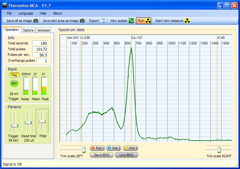
Check with the marker before each measurement is quick, accurate and very reliable. It is recommended to keep in place two small samples (for example, Caesium and Americium) at appropriate distances, so you always have two small rows of reference. Caesium is weaker and you hold it close enough to the probe while l ’ Americium hold about ten centimeters, or is enclosed in a capsule, to decrease its activity and keep him close to the probe.
The two lines should be the same height and small enough not to disturb the measurements. If you do not have to measure precisely the cesium and l ’ Americium, then the two markers can always stay in position. See their lines on the final chart (possibly commented) from the security that the chart is perfectly calibrated.
Build a well in lead
To use to measure the level of radioactivity and radioactive substances, natural background.
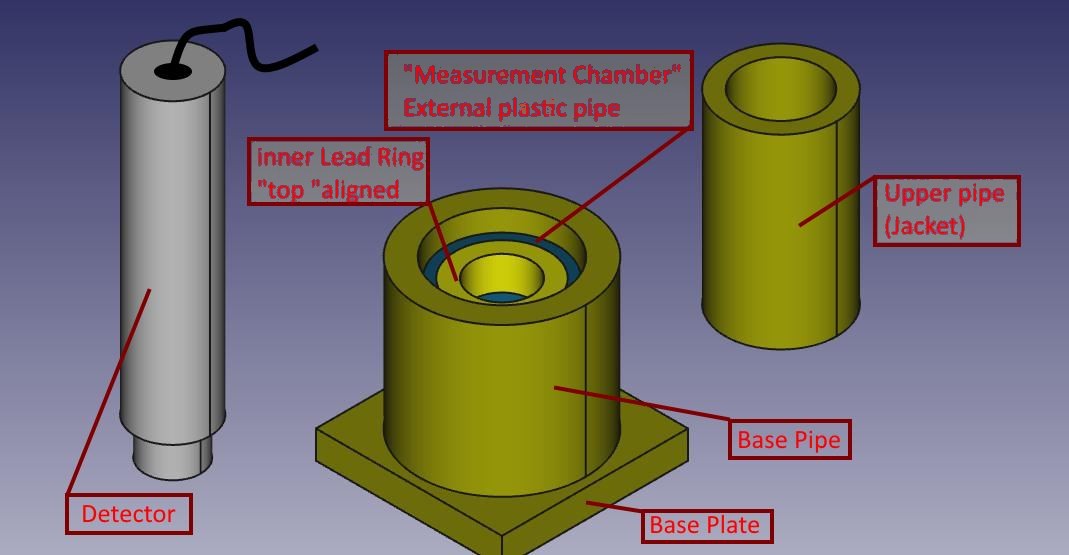
The measure consists of a base plate, plus some concentric cylinders, of various sizes and thicknesses. Among the components leaves something’ of slack, in order to facilitate the Assembly ’.
The material is actually brass lead, to distinguish it from the ’ probe grey aluminium, While the piece of inner cylinder (barely visible) is the unique ’ of plastic, with concentric ring in lead.
All the lead parts were made from sheet metal 1,5 mm thick, cut with a common Bill-sheet and shaped by hand, wrap around cylinders of aluminium/steel/plastic I had available (used only as “DIME”).
The base plate is made by folding several times a strip of sheet metal of equal width, getting a decent thickness.
Sheet bends easily around the straight edge of a table and flattens with hammer taps. The lead is very malleable.
All the pieces were wrapped with paper wide enough, so handle them does not come into direct contact with lead, that tends to get your hands dirty. Also why is good to calculate a little’ of slack between the various diameters of pieces, so then that paper coating doesn't break any insertion/extraction of cylinders all ’ same, that partially must fit one inside ’ more (as for the cylinder and top shirt)
To measure you follow this pattern:
- First arises on a table the base plate and the cylinder base;
- You insert the sample to be tested in the base tube, so that it touches the inside (lower) Dell ’ ring of the measuring Chamber: You can tuck under to it appropriate spacers;
- You put the measuring Chamber (plastic cylinder and lead supportive ring) so the below sample is centered on the bottom of ’ ring;
- He slips his shirt more than basic ’ inside the cylinder: It will support the plastic pipe and concentric ring of ’ will lead to the hole to allow subsequent insertion of the probe;
- You insert the probe : in my case straight draw in ’ ring of lead measuring nursery.
From the tests I've done this setup reduces background noise for almost 20 CPS to 3,1 CPS
Marco Russiani
Download this project, complete with more information and pictures:
![]() Theremino_Pozzetto_di_Misura_ITA.pdf
Theremino_Pozzetto_di_Misura_ITA.pdf
![]() Theremino_G-Ray_Test_Chamber_ENG.pdf
Theremino_G-Ray_Test_Chamber_ENG.pdf
Power supply
——————————————————————————————————
A good PMT power supply must be stabilized, the PMT amplification changes with the supply voltage.
With a not stabilized power supply, every little change in the ambient temperature, shifts the isotope lines making very difficult to do any serious spectrum.
In addition, because Gamma Spectrometry needs long analysis times, if the voltage changes, the rows will be enlarged, and the resolution reduced.
Some producer, like Gamma Spectacular and other kits or projects you can find in Internet, are using not stabilized power supplies but then they say something like this:
“Wait 10 minutes of stabilization before to start”
“Test the calibration with Cesium before and after the analisis,
if the calibration is changed in this time, repeat the analisis.”
they do not say this… but…
“Do not change the room temperature, do not open doors and windows…”
Negative Power supply
——————————————————————————————————
It is better to use a positive power supply, so it will be possible to use the same shielded cable for the signal and for the HiVoltage
This is not only to simplify the connections but mainly to avoid ground currents created from the double wiring ground loops.
With a double wiring it is possible tu use the “normal” power supplies (commercial HV generators) with about 10mV of noise because the switching noise is not applied to the anode.
But with a double wiring you can get a maximum dynamics of about 60dB because dynamics is degraded by HUM and cable noises. (with our single wire solution now we get some 110 dB as you can see in the documentation files of the ThereminoMCA program)
Please read mainly the file “PmtAdapters_ENG.pdf”
Hardware ADC
——————————————————————————————————
There are no hardware ADC with the requested dynamics so all the hardware MCA are using complicate methods (“Sliding Scale”, “Pole zero compensation” and other very hard and expensive methods to get a reasonable number of bins)
The hardware ADC can be very fast (maybe 1Mhz) respect to a audio ADC (192 KHz)
But audio cards are so requested in the past 20 Years that they have achieved incredible performances. The audio card ADC are 16 bit and are internal oversampled so it is normal to get about 110 dB of dynamics (about 40 dB more than a normal 10 ADC with a fraction of its cost)
Signal conditioning circuit
——————————————————————————————————
Either using a hardware ADC or a soundcard ADC the signal must be enlarged because the PMT times are about 100 to 300 NS (3 MHz to 10 MHz)
If the PMT pulses are not enlarged the ADC aliasing produces a strong degradation of the overall system resolution. (isotope rows are enlarged)
A good signal conditioning circuit must produce a well balanced and slew limited signal.
Please read the file “PmtAdapters_ENG.pdf”
bye
Livio
Is there a limit to the number of pulses per second that can be read by a "Sound Card"?
To avoid pileup you might dismiss the source or interpose non-metallic screens?
How many usable channels?
Thanks for the interesting questions, are a good opportunity to talk about these issues.
LIMIT OF PULSES PER SECOND
The limit of pulses per second is absolutely not a problem for all normal laboratory analysis.
Impulses per second are always too short.
Using a (good) sound card, as USB ones recommended by us, the sampling rate is 192 KHz pulse limit per second approximately 5000
SOUND CARDS AND SIGNAL CONDITIONING
It is recommended not to use sound cards present on the motherboard of the PC why are immutable. Using USB adapters instead, signal conditioning (limitation of slew rate and zero-pole-cancellation) We completed the sound card itself, with a high-pass 6 DB/octave which reduces low-frequency noise and produces a final push to form perfectly "bipolar". Further changes to our sound cards it's the power supply along the same signal cable to avoid ground-loops (rings of masses produced by wiring with double cable for power supply and signal)
SIGNAL TO NOISE RATIO
Using ADC to 16 bits and over-sampling sound cards can give you up to 110 DB of signal-to-noise ratio (at least 40 DB over the wretched 60 DB obtainable from ADC to 10 bits of the MCA hardware)
ADC sound cards, in conjunction with ultra low noise power supply we studied and with our signal conditioning circuitry, manage to produce an incredible final noise only 70 UV eff (micro Volts not millivolts!)
INTERPOSE METAL SHIELDS
If you were to analyze a piece of the exploded reactor (What I wouldn't recommend to anyone) It would move a little. Interpose screens is not a good idea because all the energy-dependent attenuation and shielding materials they can produce x-rays that raise the carpet of noise in some parts of the graph.
Remove the sample produces an attenuation constant at all energies (We're talking about gamma rays), attenuation that grows with the square of the distance and is easily adjusted.
USABLE CHANNELS
The application Theremino MCA has a regulator of the number of channels to six locations and a limit to 4096 channels. You could easily raise the maximum limit but so far no one has found it useful (increase too much the number of channels reduces the rate of filling of the same)
The limit given by the ADC and the signal to noise ratio, è invece oltre i 60 000 channels (e qui si vede la vera differenza tra il nostro approccio e quello degli MCA hardware del secolo scorso)
I want to say A GREAT BIG THANKS for the English translation on the latest Theremino software. I know it must have taken many additional hours of work to complete, and want the Theremino Team to know how much we appreciate it.
Please keep up your wonderful work on this truly amazing software! Your team is very much appreciated!
Tom Hall / iRad, Inc.
Hi. Great project. I have one question. On the schematic DZ1 is MMSZ5270 this is 91V zener diode.
We need there 9.1 or 10V zener. Please correct me if I am wrong.
Thanks
Yes it is true, the MMSZ5270 is a SMD 91 Volt Zener, but it must be a 9 to 10 Volt zener.
Normally we use a 1N757A.
Version 3.3 of the schematics and building plans is here: https://www.theremino.com/technical/schematics
Thanks for your observation.
bye
Livio
The PmtAdapter Version 3.3, with all the last improvements is published here:
https://www.theremino.com/en/technical/schematics/
The images are detailed and can be enlarged with the left mouse button or downloaded with the right mouse button.
Greetings from Australia and many thanks to the Teremino team for your remarkable work in hardware and software and to share your inspiring results so generously open source!
While I am waiting for the Geiger Adaptor, master and tubes to arrive I am now also considering the MCA and did some costing of the probe.
The best price I could find for an enclosed NaI cystal 1 ½” x 1 ½” has been roughly $ 230 including shipping (Sinoma, China via Alibaba) with a 2×2” about” about $ 320 to the door.
Using the same Phillips Photonis PMT XP5312/SN as in DIY Physics Paint Can scintillation probe project
http://www.diyphysics.com/2013/01/12/a-low-cost-super-sensitive-paint-can-scintillation-probe-for-the-prutchi-cdv700-pro/
and mentioning this project when ordering from the supplier Sphere
http://www.sphere.bc.ca/test/photo-tubes.html
the tube can be bought for a reasonable $ 49 plus shipping
.
In the Paint Can Probe project they only use a Bicron plastic scintillation crystal, which generally claimed is not suitable for gamma spectrometry.
However, googling this I found that new doped plastic scintillation materials have been developed with much improved properties suitable for spectrometry but I could not find a supplier, only scientific papers. There are also papers describing calibration and correction methods for plastic scintillation materials to make them useable in spectrometry.
Could these methods be employed with the MCA making possible the use of an inexpensive scintillation probe using a plastic crystal?
Does anyone know a supplier or has more details for the improved plastic scintillation materials?
Will there be assembled PMT and audio cards available? Thank you and
Kind regards
Eckhard
Hi,
we are very interested to make inexpensive scintillation probes using plastic crystals or maybe some liquid that can be painted on the sides of a Paint Can.
Calibrations and corrections are not a problem, our software can do any required operation and we can easy add new corrections.
The problem is the resolution of the scintillator material, we tested a BICRON BC408 (1 x 1 x 1.5 inch) (10 Euro) with a FWHM of about 60% at 660 Kev – Maybe the version 4 of our software can increase a little this resolution but not down 40% or 30%.
The BGO we are using is not expensive and (with our version 4 resolution compensator) has a resolution of about 10% or a little better (but the Radium rows are not well resolved)
We searched for long time, other good scintillator materials without any result.
————————–
Please consider also that the “Paint Can” Probe project is not so sensitive as they claimed (with the Hamamatsu PMT and a little BGO we get about 25 times more CPS)
I do not know why but I suspect that the scintillator they use is not so good.
bye
Livio
========================================================================
Alcuni utenti non riescono a ridurre il rumore del PmtAdapter, copio qui alcuni brani
su questo argomento, tratti da varie mail.
I consigli sono in inglese – gli italiani possono fare TASTO-DESTRO -traduci in italiano.
========================================================================
Version numbers and Current Limiter
———————————————————————————————
The Audio Card has not a version numbers but in the last weeks we added the “limiter”
Test always if the jack is completely plugged
Without the limiter – if the jack is not completely plugged –
the inductance in the Audio Adapter can MELT !!!!
When Alessio has finished the limiter PCB it will be possible to send to you a “limiter”
please call to Alessio for this.
If you prefer I can install it for you or you can see here how to make it here:
hardware/outputs/actuators (the SMD version at the end of the page)
The limiter substitutes the inductor in the audio card also with better results (less noise)
Capacitor in the Pmt Adapter
———————————————————————————————
For some user the noise way is: L1 – L2 – R14 —> OUT
– C13 and C14 must be LOW-ESR (Max 0.03 ohm series)
– L2 must be 1mH (Max 2 ohm series)
The LOW ESR capacitors are very important !!!
– normal capacitors are 1.5 ohm series resistance
– low esr are 0.03 ohm resistor
The difference in noise reduction is 50 times.
And it is very easy to mount wrong capacitors
because the text “LOW-ESR” is not present on the capacitor body
Capacitor in the Audio Card
———————————————————————————————
Also the capacitor in the audio card must be LOW ESR (220uF or 330uF)
In the first PmtAdapters this capacitor was not OK
Sorry for this !
We are not professional producers, we are a “Non Profit Organisation”
Alessio was making some kits for the friends but never thinked to make so many
kits in so little time !!! And all the people was pressing to get immediately the kit…
I can personally send to you some euro, to compensate for this errors, if you send
to me a PayPal button – or you can considerate this a donation to our organization.
Jack with instable connections
———————————————————————————————
We found some audio card with the jack plug not OK
Try to rotate the jack to see if the noise changes
If the noise changes then the jack plug GND contact is not pressing OK on the jack
Open the card and bend a little the three plug contact to make them more solid
USB connections and/or USB noises
———————————————————————————————
Sometimes also the USB plug of the computer contacts are not completely clean.
Try to move slightly also the USB
Try also to use another USB port
(every time restoring the AGC = OFF and the minimum mixer volume)
Try also on another PC to verify if the noise comes from the USB
(some PC has a USB producing a great switching noise)
bye
Livio
========================================================================
Alcuni utenti che si procurano i componenti da soli hanno trovato difficile reperire:
– lo Zener 1N757 da 9 Volts (questa sigla era anche sbagliata negli schemi)
– il Mosfet BSP 300
Copio qui alcuni brani su questo argomento, tratti da varie mail.
I consigli sono in inglese – gli italiani possono fare TASTO-DESTRO -traduci in italiano.
========================================================================
Zener
—————————————————————————————————————–
The zener is now corrected with the 1N757A
The 1N5239 is not a good equivalent, it has a too high leakage courrent
1N5239 = 3 uA1N757 = 0.1 uA
Mosfet
—————————————————————————————————————–
Someone has proposed the STN1NK80Z but I think it can not work
(or work with a low effciency, more current consumption,
and only if the max output voltage is limitad to 800. 1000 Volts)
Drain courrent with gate-source voltage = 4.5 Volts
STN1NK80Z = 10 mA
BSP300 = 200 mA
The first four sellers can send to you the BSP300
the number of pcs is the quantity actually present in the wharehouse
Alessio ... BSP300 ........... 5 pcsFarnell ... 1471698 .......... 10666 pcs
Distrelec . 610259 ........... 183 pcs
RS ........ 752-8211 ......... 45 pcs
DigiKey ... BSP300 E6327-ND .. (actually in backorder)
Mouser .... 726-BSP300L6327 .. (sometimes it has cutted Tapes)
In Poland inter-chip.pl has BSP300. (i dont know how many polish guys are interested in this project :))
Only parts i could not get are C5 and C6. I used MKS4-47N/1500VDC poliester capacitors to filter output. (i dont know how much this affect quality of output voltage??).
My PmtAdapter is working. Few things left: aluminium box, shield. sound card mod.
When I finish i will Donate theremino :) You are awesome !
Dear Martin,
your MKS4-47N/1500VDC are only more large and more expensive, but electrically they will work absolutely OK
Another possibility is to use 2 x five 10nF/2000V ceramic disk capacitors that can be easy find on eBay (making 20 holes on the PCB with the Dremel)
Please make also, great attention to use 1000uF LOW ESR capacitors with not more than 0.03 ohm series resistance ! And 220uF LOW ESR in the Audio Card.
It is difficult to reduce the noise, Although a good spectrometry can be done with 2 MV and more, We need better. "We are not like a normal “iPod to Audio Card” user, We are very picky and we want to pep 200uV noise !!!
I wanted to thank the Theremino team for the excellent work done.
I recently got the Theremino adapter, getting remarkable results on all fronts.
I must say that I was initially a little’ skeptical about the system calibration: I had tried one of the versions “2” of the program, with the Spectacular Range, but the result had me excited.
Tutt’ different matter now, with the Theremino adapter and the version 4.6 of the program: excellent results and precise calibration and stable over time. Really an excellent spettromentria system at a fraction of the cost needed to get similar results with the methods normally used so far. Also notable is the mass of information that you have provided in the Docs folder, very useful for those, like myself, It’ of course a “electronic wizard”.
Finally a great “Thank you” to Alexis for kindness, speed’ and generosity’ with that solved a problem caused by my lack of experience.
Continue so’ and best regards to all of you !
Luigi
I see that you have arrived to version 3.3
I have version 3.1
What is the performance difference between the two?
Known by the scheme that the 3.3 mounts both the transistor that the mosfet
Both can be mounted or, either choice
I am pleased with my Theremino but if with this version I can get improvements
I can provide for the upgrade
Fiorenzo
The version 3.3 only has minor differences on the printout:
– resistance from 2.2 ohm on solder side
– a jumper to select the HF (not to be used if all goes well, as in your case)
– screen printing made better
As performance does not change anything
And even the transistor is not better than the Mosfet.
The transistor serves as an alternative for those who cannot find the Mosfets but not by any advantage, Indeed consume a 10 but add-.
Livio
Theremino MCA version 4.5 was used to test this sample of black fungus like material, that came from Japan. This resin encapsulated sample has reportedly come from somewhere in the Minamisoma area Japan. A contact in Japan sent this sample to a friend. This is my test chart of it.
http://sccc.org.au/wp-content/uploads/2013/04/Minamisoma-Cesium-290313-TV45-23c-25040-MB.jpg
This fungus started growing on the concrete, and rock surfaces in lots of places in Japan, after the Fukushima Nuclear disaster. It appears to be bio-accumulating Cesium.
Scintillators are less sensitive as you go to higher energy keV. The Theremino MCA software allows you to increase the magnification of the higher energy peaks. The peaks in this Theremino MCA V4.5 software chart have been energy compensated, to bring out the smaller details at higher energies. The sample very small, grams or less.
A professional lab reported test results 117 Bg Cs-137 and 58 Bq Cs-134.
I don’t know the exact weight. Spectrometising is trying to find out.
Any comments or suggestions, regarding the results of this test chart results are welcome.
There is no copyright placed on the chart screen shot, so you can copy it, and make use of it where ever you like.
This is a very detailed and interesting image!
Thanks for your reasearch and, please, send to us any news.
We published your image here:
https://www.theremino.com/blog/gamma-spectrometry/images
bye
Livio
This black fungus material sample from Japan, contaminated with Cesium Cs-137 & Cs-134, is encapsulated in resin for safety reasons. So we don’t know how much it weighs. We are trying to find out. It may not have been weighed when it was collected. Visually, looking at the encased sample, it would be a few grams if that.
Here is a pen tip placed next to the sample, to give you and idea how small the sample is. The black center is the sample. Also, the sample does not fill up the small sample container, that is in the center of the resin encasement. The sample container is only around two thirds full.
http://sccc.org.au/wp-content/uploads/2013/04/Japanese-black-fungus-material-sample-with-pen-tip.jpg
Hi. What size of crystal (NaI(TL)) was used ?
Are there any plans to run Forum here on theremino site? i done my pmtadapter and detector (now fine tuning) and it would be great to share expierience with others that use PmtAdapter and theremino MCA. (i know yahoo groups and fusor.net)
Martin S.
“What size of crystal (NaI(TL)) was used ? ”
Voltage Setting:
800 Volts, tried 850 but put it back to 800.
Scintillator:
Alpha Spectra NaI, Model 818/2B, resolution 7%
Scintillator:
2″ x 2″ Alpha Spectra NaI, Model 818/2B, resolution 7%
Suggestion,
It would be great to have a Theremino MCA program feature like the FWHM for Bequerel calculation. After the efficency of your scintillator is worked out, and entered in the settings, the software could be used to calculate the becquels amount for a highlighted peak area.
Bequerel is the number of decays per second and it is not possible to measure the decays produced by a sample.
It is not only matter of efficiency but also of geometric parameters, of distance from sample to scintillator, wall material, sample emitting area, scintillator capture area, and many other factors.
If some of those parameters is changed, for example the distance by some mm, the measured value can change by 100% or more.
With our sensors (scintillators and PMT) it is not possible to intercept all the decays or compensate with a “correction parameter”
With our sensors are possible only relative measures.
So we prefer do not increase the erroneous idea that Bequerel and Curie values can be “measured” without a complete specification of those parameters.
We know that other software, and also Geiger counters like GammaScout, are doing this but it is not correct.
“It is not only matter of efficiency but also of geometric parameters, of distance from sample to scintillator, wall material, sample emitting area, scintillator capture area, and many other factors.”
Agreed
Even scintillator efficiency varies from low to high keV.
Still, would be nice to know the number of counts in a given peak area. PRA allows you to highlight a peak area, and then it totals the counts for that highlighted peak area.
Yes, the “area total counts” and maybe also the “area counts per second” are useful indications.
Thanks for the help, we may include it in the next versions, maybe with the names “Total” and “CPS”, if you agree.
In the meantime you can do a left click on the graph, and read the counts for each bin in the status bar. With some experience it is not difficult to estimate also the counts for the other parts of the graph.
“Yes, the “area total counts” and maybe also the “area counts per second” are useful indications.”
Yes, I think that it would be a positive additional feature to an already great program.
Here are two charts of a 100 grams of pure Potassium Chloride. The charts were recorded in Theremino MCA V3.8 and V4.5, for comparison purposes.
The chart recorded with Theremino MCA V4.5 has a lot better FWHM, and is showing more detail than the V3.8 chart.
http://sccc.org.au/wp-content/uploads/2013/05/Potassium-Cholide-100-grams-010513-TV38-22c-855546-texts.jpg
http://sccc.org.au/wp-content/uploads/2013/05/Potassium-Cholide-100-grams-010513-TV45-22c-89647-texts.jpg
Thanks, very good resolution and perfect settings! It is very difficult to see the Potassium Chloride and there are very few images about it. It is so difficult that someone says that ThereminoMCA not works at so high energies.
Sorry that the images were taken in full screen and then reduced to 800 pixels, so the writing are difficult to read. It would be better to keep ThereminoMCA non-fullscreen.
Here are the original full size screen shots. I resized the images in the above post, because on another forum you could not see the all the image on the screen.
http://sccc.org.au/wp-content/uploads/2013/05/Potassium-Cholide-100-grams-010513-TV38-22c-855546-text.png
http://sccc.org.au/wp-content/uploads/2013/05/Potassium-Cholide-100-grams-010513-TV45-22c-89647-text.png
Yes thanks.
So I have not explained well the problem…
Now I try to explain it better.
If the ThereminoMCA is used full-screen or with a large window, the grabbed images will be large (1280 pixels or more)
It is not possible to see so large images on the WEB, on the NetBooks and on tablets (and it is very annoying to zoom and pan them continuously)
There are no advantages to use large images and to use ThereminoMCA in full-screen, but only disavantages:
1) The spectrum rows are not better if using large windows but the text becomes proportionally little, and not proportioned with the graph
2) The equalizers can not be docked
3) When the images are reduced to a Web-Friendly 800 pixels the text will be poor and diffcult to read
4) When the images are reduced all the image becomes de-focused
The good solution is to work always with ThereminoMCA in a window, with width about 800 or 900 pixels.
In brief,I have a scintillation detector SPP-2-NF functioning and outdated….
can be used for tests with MCA or other good programs that deliver ? The champion of Cs137 outfit indicates 256 C/S, While the tool reads 150, I think depends on the natural decay,which says a lot about the age of all… I don't know if this is the right place for this info,If show me the correct way to do it,I'm waiting for the arrival of the circuits Geiger ,just to stay on topic!? Congratulations to the quality level of the circuits and explanations,Thank you for the time that I took, cordial greetings, Claudio
I gave him a look and appear to contain a photomultiplier tube and a Crystal Nai(TL) – These are the only two components. I would say that used might be worth around 150 Euro (always work well and that we can change them for mass spectrometry)
They speak of basic 30keV so so’ How come’ and’ very loud for mass spectrometry. To make it work well the hoof of the PMT should be rewired according to the instructions of our PmtAdapter. Then you'd have to make or buy a Separate kit, write to Alexis for precise directions on prices: alessio.giusti@meteolink.it
If you want to use it like this’ like ' and’ potresti tentare di mandare l’audio out di cui dispone verso la scheda audio e contare gli impulsi con theremino AudioIn e ThereminoGeiger, oppure vedere se i suoi impulsi sono adatti anche per la spettrometria con il software ThereminoMCA. Usandolo cosi’ le caratteristiche saranno scarsine ma non spendi niente e non devi modificarlo.
Hello
Livio
Is this proof, that some of the Beryllium Be-7 in our rain tests here in Australia, is from Fukushima?
For background on this subject, please read this article on using Beyllium Be-7 as a tracer for I-129.
http://www.sciencecodex.com/dartmouth_scientists_track_radioactive_iodine_from_japan_nuclear_reactor_meltdown-89004
————————————————————
* Be-7 is produced by cosmic ray spallation in the upper atmosphere. It takes around two weeks to reach sea level. My understanding is that the Japanese have been pumping large amounts of liquid Nitrogen onto the multiple molten coriums at the Fukushima Nuclear disaster, to cool them down. The neutron bombardment, plus lots of underground corium venting, has also been releasing large amounts Beryllium Be-7 and 1-129.
True or False?
————————————————————
There is a natural Beryllium Be-7 and Lead Pb-210 cycle here in the Southern Hemisphere. There is a more Beryllium Be-7 and Lead Pb-210, detected in rain washouts, during summer than in winter. There appears to be above averag detected Beryllium Be-7, in this test for May 2013. The Sun had been relatively quite during May 2013.
So the question.
Is some the detected Be-7 being detected here in Australia from Fukushima? If there is a significant presence of I-129 and U-235 in the rain here, it suggests that it is. That the Be-7 has travelled here from the Fukushima Nuclear Disaster.
This is open for discussion, I am interested in constructive feedback, and alternative views on the test results.
Looks like a detection of Iodine I-129 from the tin roof down pipe polyester filter. It was collecting rain off a 36 sqm tin roof at my location.
Test chart using Theremino MCA V4.5 software.
http://sccc.org.au/wp-content/uploads/2013/06/Down-pipe-polyester-filter-020613-TV45-20c-88395-+-text.jpg
If it is, it is still a very small detection of I-129, because the filter was in place for all of May. Mind you, not all of it would have been captured using this filter system. Lots of Beryllium Be-7 is also present! If this is present in the Southern Hemisphere, it would suggest that there is a lot more in the rain in the Northern Hemisphere!
Nimbin Australia has been getting huge Radon washouts this year. The rain swab test charts from that location have been showing lots of Lead Pd-210 and Beryllium Be-7. Lead Pb-210 is the end isotope of the Radon daughter decay chain.
Nimbin test chart using Theremino MCA V3.8 software
http://sccc.org.au/wp-content/uploads/2013/06/East-Coast-Northern-New-South-Walles-rain-swabs-96-+-69-test-070213-TV38-Be.png
Theory
Because the I-129 at 39.6 Kev, and Pb-210 at 46.5 Kev, have energy peaks so close together it can be difficult to tell them apart with a NAI scintillator. If they are present at the same time, the peak that shows will drift toward the 39.6 kev if more I-129 is present, and towards 46.5 keV if more Pb-210 is present.
The experimental Theremino MCA V4.5 software used in this test, is a bit noisy near background. It is a lot more sensitive than the other scintillator MCA software I use. It is just that the noise at low CPS activity can make it harder to interpret isotope peaks.
Beryllium Be-7 has a theoretical back scatter peak at around 166 Kev, very close to the 185 kev for Uranium U-235. There is the possibility that it is contributing to the size of the peak at that the U-235 location. It may also explain the width, and rounding of that peak at around 185 Kev.
Disclaimer: I am an amateur. Human error can provide incorrect information, and equipment malfunction can produce false readings. Do not rely on, or take action upon information presented here, without further research.
Ho installato Theremino MCA e collegato il modulo PMTAdapter fornitomi da Alessio. Il tutto ha funzionato immediatamente ed una volta impostati i corretti valori di energia forniti dalla mia sonda, si è generato un grafico di ottima qualità usando le classiche sorgenti Am241 e Cs137. Non ho avuto necessità di leggere il manuale, What I'm actually doing now to deepen some adjustments. I had doubts about my probe made by plugging them into a Ram63/3 a NaI(TI) from 1.5″ x 1″ on the old PMT originally matched to plastic scintillators, but the yield looks great for sensitivity (6000 CPM for the Fund) and seletività.
Congratulations to Alexis and Livio and associates.
A question. With XP to set the input volume is fine click of mouse from scratch, in order to make repeatable measurement. With Windows 7 the first click returns in a window on the numeric value 20 which corresponds to a value of about noise 0,7 Kev with the green line just above the baseline rossa. But the value can be set numerically on the window, so I tried the value 8 It gives me an average noise ranging from + 0, 2KeV and -0,1Kev. Much lower then. The question is as follows: the fact that with this adjustment the impulse line Green is superimposed on the red line and invade the field slightly negative values may result in some inconvenience at the level of software features?
All operating systems you must always set the minimum position gain still working. With XP this location is not really with the slider to zero because otherwise the input switches off. With Windows7 and 8 You must place the cursor right at zero or put the number as low as possible.
In this way it decreases the maximum gain of the audio input and minimizes the ADC noise floor of the sound card.
Reduce the minimum amplification also allows you to send electrical signals around the input volts peak to peak without being fleeced by the minimum and maximum limits of the ADC.
The end result is to maximize the relationship between signal and noise (maximum signal before clipping divided ADC noise + noise on cables + power supply noise)
Gain reduction is then easily compensated by increasing the tension on the PMT
In this respect I still recall all that you must keep the adjustment slider, located right at the bottom of the main window, approximately half of its stroke, and adjust the tension on the PMT to keep him so. Otherwise you may not exploit the full dynamic or high energy pulses of shear.
The location of the green line
———————————————————————————————–
All sound cards, some of the other less, have the zero line slightly high or low. Change regulation of input sliders move noticeably this position for which you have to place these cursors don't move steadily to a minimum and more.
Then you compensate the Green row position with “Audio zero trim”
– By disconnecting the BNC that goes to PMT
– Disabling the base Line Test
– By Setting MinEnergy = 0 in order to view basic noise PulseShape Visualizer
– Or using “Tools NoiseTest” that does this automatically
Without Baseline Testing
———————————————————————————————–
If the green line is too high you get the noise low energy, instead if it is low the lines moving left and low energy impulses disappear below zero.
With the Baseline Test enabled
———————————————————————————————–
The location of the green line does not count anymore because it is recalculated at each imulso (but it's okay to have approximately zero in order to make good use of the Pulse Shape Visualizer)
In all cases
———————————————————————————————–
If the green line is slightly above or below the red line you don't get significant changes in working. With “slightly” means a few hundred uV.
Thanks for sharing this interesting questions on the blog.
Hello
Livio
Thanks Livio for the detailed instructions.
But at this point is a matter. My probe (with the classic voltage divider 13 10MΩ resistors and one from 1ΜΩ) agree to be powered with 1300V tops. Further increases do not move the chart to the right, or the energies do not increase. If I set the audio volume to 5%, slider at the bottom right in the Center and Equalizer disabled, the peak of Am is to 25-30 Kev and the Cs to 250 Kev. By setting the volume with a click (20%), the Am returns 50 Kev and the Cs 490 Kev.
To resolve this problem I can:
1. leave the volume at 5%, do the full extent and eventually stretch the graph to the right up to match the energies with the characteristic values.
2. increase the volume to 20% and optimize your energy with the equalizer and the slider at the bottom right.
3. rewire the probe with resistors (What value?) I return the most energetic pulses.
Any suggestions? Thank you
I could not tell how to rewire the probe to have more signal, don't think it's possible.
Probably your PMT has a rather low gain compared to Hamamatsu I'm used, I'm sorry but I've never tried a Ram63.
I'd say you're going to have to work with the mixer on the 2nd or 25% and agree to have something to 0.5 to 0.9 MV of noise… If you're under the ultra-low noise however is always a millivolt and probably with Ram63 you can't do better.
The version 5.0 just published no longer fooled by the noise and ringing before the pulses, and then a minimum of noise will not prevent you from seeing the same extremely low energy, even under the 5 Kev and, in some cases up to an amazing 2 Kev. https://www.theremino.com/downloads/radioactivity
However you will need to find you the most suitable combination of parameters for best results with your hardware, Let us know how you've stabilized… Thank you, Hello, Livio.
Thanks Livio. Under 1 MV I remain anyway. I will update
Solved! It was a problem of optical coupling between PMT and Crystal. I put the silicone grease ex novo and the energies are enchanted doubled. Probably an air bubble between the surfaces. With a little tweaking of the right-hand cursor Cs is centered.
Very good, so if I understand you correctly you have the cursor to a minimum (at least marks 5% ?) and you have the voltage below 1300 Volts ? I'm a little’ boring to ask all the details but I'm doing it for others who might have a Ram63 and find useful your measurements.
I forgot, the increase in signal definitely has a good effect on resolution, What is the width of the row of caesium in FWHM? And maybe we're glad if you write even the crystal type, Maybe you've already written, or perhaps it is implied since you a Ram63. It's probably a Nai(TL) but I read that someone replaced it…
I installed Theremino MCA on XP and on Mac with Windows 7, so I can vary the input signal with freedom. Between about ten days I will answer more precisely since I will be on vacation and I will have more time to test.
In principle the FWHM value varies with the equalizer settings between 6% and 11%. In order to have a fairly accurate value, the measure without equalizer and with different values of audio input.
The Crystal is a NaI(TL) from 1.5″X 1″. Ho scelto queste misure in quanto il suo involucro esterno corrisponde alle dimensione del cristallo plastico originale ed ho potuto quindi inserirlo nella sonda RAM senza modifiche meccaniche.
Hi Livio,
I made few tests with two scintillation detectors with ver5.0 and my conclusion is that Theremino is finally superb MCA software. Details and lower energies are now much better with better resolution. Data acquisition is the fastest as it ever have.
With no changes for both (different) probes result is great and with little fine tunning I get superb results and all that after few minutes of tunning. Sure I need to get all voltages tunned and then will be finall results but this is also very good.
PRA had better results in lower energies below som 30 or 40 keV compared to older versions of Theremino MCA and now Theremino from v5 have much better.
Congratulation for great improvment!
Tomy 9A5TOM
PS: As soon as I get few days off off my job I’ll make those new video on my YT channel. Now I can say that it was good that I wait for v5 ;)
Report is ready if you interested into let me know. I published it on GammaSpectrometry group.
A great test, and a great help for us, thanks.
The Ra-226 spectrum is very detailed and the Cs-137 row is narrow, what is the FWHM?
This is the link to the GammaSpectrometry group message:
http://tech.groups.yahoo.com/group/GammaSpectrometry/message/13021
Hi Livio,
Resolution (FWHM) for 662keV for Cs-137 is 7.1%
I get few comments about issue in background substraction.
Please see message thread. I don’t know what kind of algorithm you are using but it is maybe little bit too rigorous. I made calculations in MS Excel (2013) so please read this message:
http://tech.dir.groups.yahoo.com/group/GammaSpectrometry/message/13031
Read notice, it’s not 100% accurate but as a reference is good.
If I can help somehow in that part please let me know.
Kind Regards,
Tomy
The subtraction is only a simple subtraction x=a-b, sorry but I can not figure why it can not work at the best. You can try to discover this.
I sending you mail with formula and explanation.
El programa nos resulta muy útil y práctico, pero tenemos problemas para realizar cálculos en los espectros. Contamos con un detector de radiación Gamma Spectacular GS-1100A, los espectros registrados por éste programa son buenos y fáciles de interpreta, pero requerimos cálculos sobre esos espectros, como determinación de ROI, centroide del fotopico y FWHM entre otros, to determine the activity of the isotope associated with its spectrum.
We would appreciate information about the topic.
It would be very useful to meet more people in Latin America which have similar systems in Gamma spectrometry.
Best regards.
Dante Rios
Physical
Lima, Peru
contact: danrisa@hotmail.com
The FWHM value and the center of gravity is obtained by pressing the mouse left or right at the peak of your interest. (With the two buttons that gets an automatic or manual)
The FWHM value is displayed in the main window and the center of the bottom status line.
You can also save the data and treat them with an external program.
There are also new versions of ThereminoMCA with new options in evidence on this page: http://pico.dreamhosters.com/ThereminoMcaEn.html
(Este enlace también está disponible en la página de descarga de ThereminoMCA)
saludos
Livio
Detection of radioactive Iodine I-129 in roof gutter moss Australia.
I used Theremino V5 for the tests discussed in this report, so I thought you may be interested in the charted test results.
I recently collected 82 grams of moss that had been growing in roof gutter here, and tested it. It was very wet here for the first half of 2013. August has had no rain, so the moss sample was dry.
I am located here on the east coast of Australia.
http://sccc.org.au/monitoring/Australian-Map.jpg
Moss growing in roof gutter
http://sccc.org.au/wp-content/uploads/2013/09/Moss-growing-in-roof-gutter.jpg
Moss in Marinelli beaker for testing
http://sccc.org.au/wp-content/uploads/2013/09/Roof-gutter-moss-82-gams-in-marinelli-beaker.jpg
Test chart of moss sample using experimental Theremino MCA version 5.
http://sccc.org.au/wp-content/uploads/2013/09/Moss-from-roof-gutter-80-grams-260813-TV5-19c-80781-+-text.jpg
If my assessment is correct, this Southern Hemisphere detection is not a good sign. This is a lot of Iodine I-129. The other possibility is it is Lead Pb-210, or a mixture of both. The main peak is much closer to 40 keV than to 47 keV for lead Pb-210. I have tested this sample with different software, and calibrated a number of times, it very much looks like I-129.
This means it is bio-accumulating. So even though our background levels here have not risen a lot, bio-accumulations could present a more serious issue. The moss also had some other material mixed in with it, that it was growing on, leaves and other organic matter. This test result also suggests that there would be more 1-129 in fallout in the Northern Hemisphere.
I have discussed this test result with some of my contacts here.
Why so much I-129, and not Cesium etc.?
The conclusion is because of its volatility. It can also easily volatilize in an environment, as the temperature increases.
This would allow it to easily spread long distances, like Iodine I-131.
Japanese study of I-129 pre-Fukushima Nuclear disaster.
http://www.ncbi.nlm.nih.gov/pubmed/23829385
Another pre-Fukushima Argentina study, indicates that Norther Hemisphere I-129, can reach the Southern Hemisphere. This study shows I-129 has migrated from nuclear fuel reprocessing plants at Cape de La Hague (France) and Sellafield (UK).
http://www.sciencedirect.com/science/article/pii/S0048969712006353
For the technically minded – Testing procedures, and Becquerel activity calculations.
Scintillator Model:
Alpha Spectra NaI 818/2B, resolution 7%
Voltage setting; 800 Volts
Efficiency 7% at 662 Kev
I used radioactive Americium (Am-241), from a smoke detector in the test chamber, to calibrate the low energy peak position, and also the scintillator efficiency at around 40 Kev.
Here is the calibration chart for reference.
http://sccc.org.au/wp-content/uploads/2013/09/Moss-+-Americium-+-text.jpg
Estimate of scintillator efficiency at 40 Kev
Smoke detector Am-241 activity = 37,000 CPS, from my research approximately 1% of this activity is Gamma.
1% is Gamma = 3700 CPS (36% of that 1% is at 60 Kev)
37 x 36 = 1332 cps = 100% gamma at 60 kev
1295 / 100 = 13.32 = 1%
693 cps was the actual cps in chamber for this peak region
693 / 13.32 = 52% efficiency at 60 Kev
Estimated efficiency at 40 keV is approximately 52%.
I used Japanese BecqMoni MCA software to calculate the activity.
Using 52% efficiency at 40 Kev.
net count – background = 80039
80039 / 52 = 1,539 (1%)
1,539 x 100 = 153,900 (100%)
Time of test = 79700 seconds
153900 / 79700 = 1.931 CPS
82 grams in weight 1000 / 82 = 12.195
1.931 X 12.195 = 23.5 Bq/kg
This may not be an absolute quantification of the scintillator tube’s efficiency at 40 Kev, but we are dealing with moss in a large marinelli beaker here. The efficiency of activity is going to be less than the 52% for the Am-241. So the 23.5 Bq/kg activity estimation is probably conservative.
Disclaimer: This is an amateur volunteer run service. Human error can provide incorrect information, and equipment malfunction can produce false readings. Do not rely on, or take action upon information presented here, without further research.
Hello Livio,
mi chiamo Emanuele ed è la prima volta che scrivo sul blog. First of all I would like to compliment the variety of projects on the site and in particular for the Gamma spectrometry. I come to the point. I'm building a system consisting of a probe scintillatrice Bicron NaI(TL), from Theremino PMT adapter and MCA software and after various evaluation I opted for the project Theremino PMT. I then built the PCB of the PMT adapter V 3.3 and I just finished assembling one I'm testing impatient connecting it to my probe.
I find myself with a little problem (I hope that this is the right place ...):
Fueling the PCB I am a stable voltage output on pins down approximately 450Vdc PMT , becoming thoroughly by turning the potentiometer 580Vdc about clockwise.
According to what I read on the documents available on the voltage should reach at least to 1000Vdc.
Also by reading the documentation I gather that the inductance by 3.3 uH is critical and should have a resistance of less than 3 ohms (mine is about 8ohms). Could this be the problem or is the impedance of my multimeter that is low?
Any comment will be appreciated.
Thank you in advance for your reply.
Emanuele :)
The inductance must not be from 3.3 micro Henry but from 3.3 Milli Henry, I think the problem is this. If you put it to 3.3 Milli Henry also works if you have the resistance series 8 ohm resistor. However does not work if there is a very small inductance and start downloading internally to 500 Volts or less. Must accommodate up to 800 Volts (that duplicates are 1600)
Also check the chip must be a NXP otherwise you find it hard to get to 1500 Volts.
Did you use the right low-capacity diodes? And the right MOSFETs?
Another possibility is that you're measuring with a “multimeter”, You can't do, you have to use a divider from at least a few hundred mega ohm, as written in the documentation.
If you're not write here, or call me from 09 at 19 everyday including holidays at 0125 57290, or give me a landline to call that I don't spend anything. (Maybe send it to me by mail if you prefer more privacy) my mail is engineering at sign theremino dot com.
Good construction and good tests.
Livio
Hello Livio,
Thanks a lot for the replies. I confirm that the inductance is by 3.3 mH (and not uH as I wrote, sorry). The fact remains that is from about 8 ohms. Meanwhile I found out that there are books on the PCB screen printing codes reported Farnell. I then bought those and I will arrive next week.
I confirm that it is the mosfet that diodes are exactly of the type specified in the documentation.
In fact I took measurements with a multimeter without voltage divider and then with a relatively low impedance (even this does not help).
Thank you again and I'll let you know.
A good evening,
Emanuele
Then the problem is the meter, It's not that it doesn't help, not working right.
Buy Farnell many resistors 82 Mega SMD then put 10 in a line on a Breadboard, you have to make a voltage divider 1000 to 1, for example, 820 Mega and 820 K. Finally, since in parallel to the 820 K connect a tester from 10 Mega you also raise a little’ the 820 K by adding something in series in order to have an exact division by 1000.
Or do the same with non-smd resistors, that will be up to 10 Mega or 22 or from 33 If you find them.
The important thing is that the high-voltage side of the battery isolator is composed of at least ten resistors (to keep the voltage) and that total at least 300 Mega ohm, But even better if they are 500 or 1000.
On site or in the documentation of the PMT adapter there should be some explanation on how to make a voltage divider, If you do not find just tell me you wanted me.
I am very thrilled with Mr Garcia's desire to help me get started in spectroscopy. I am on an extremely
limited budget and, have a background in gamma ray physics in the medical field, but less eperience
Troubleshooting and designing electronics. His kit for the PMT interface is very economical and I will be interfacing this kit to my netbook for some stationary and portable spectroscopy. I havent received the kit yet as of the date I am writing this… but Im sure this will work as planned, as I have thoroughly researched everything… The detector I purchased is a 5.9% efficiency NaI – while not as effective as other modern detectors -provides way more information than a simple gm tube. The kit was just under 200.00 and the detector was 300.00 . A spectroscopy system for 500.00 is basically unheard of. From visiting antique stores to identifying minerals in old zinc mines (a hobby of mine, fluoresecents) this should be a terrific system.
Hi,
I just wanted to say how impressed and thankful I am for the work that the Theremino team has put into the MCA and PMT Adapter!
I just received an assembled PMT Adapter from Alessio (thanks for the great support!). Within a few minutes I had it installed and creating spectra with the Theremino MCA v5. I didn’t have a proper probe made, so I started out just using BC-412 and the PMT from a paint-can scintillation probe… I still got recognizable results… Everything came up so easily!
Now my NaI(TL) crystal has arrived and I’ve got to finalize a probe design (PMT and housing) for it. I also need to properly learn the MCA program, for example, I don’t understand how to use the sliders properly (especially the y-axis slider, which seems to dramatically change the look of the spectrum!).
Thanks again to all involved!
-mark.
All the sliders are explained in the documentation accessible with the menu Help.
Please read the “Program help” pages 3 and 4.
In the first times please do not use the “Max” button (leave it gray and relaesed)
The (undocumented) “Max” button maxes the vertical scale manual and has been added to follow the desire of some users.
Brilliant project – I cant wait for the parts to arrive. I’m having a little a little trouble finding the 47nF 1.5 kV SMD capacitors. Can someone point me in the right direction to find them? Thanks.
Those (or similar) capacitors can be found from:
– Farnell : http://uk.farnell.com
– Mouser : http://www.mouser.com
Or you can buy on eBay ten 10nF-2000V ceramic disc capacitors
and place 5 and 5 on the PCB making 20 holes with the Dremel
For example this:
http://www.ebay.it/itm/50x-Keramik-Kondensator-radial-10nF-2000V-RM7-5-HF3D103M13R726-/230756725779?pt=Bauteile&hash=item35ba2c3413&_uhb=1
Remember also to cut the GND between the two capacitors…
As explained here:
https://www.theremino.com/en/blog/gamma-spectrometry/hardware-tests/
bye Livio
Thanks very much, that’s great advice. :)
I completed some tests with ThereminoMCA 5.0 and PmtAdapter 3.3, and I must say you have done (and you are doing) a really excellent work!
To get a decent calibration, I used cumulatively the following sources “housewives” in order issuing crescednte:
K-40 (1460 Kev: potassium carbonate)
CS-137 (661 Kev, 32 Kev: CK1097 tube-12)
Th-232 (238 Kev, 338 Kev: retina for gas lamp)
Am-241 (26 Kev, 59 Kev: smoke alarm)
I faced the probe the first source and I looked forward to that characteristic peaks were well formed, After that I suspended the run and regulated linearization cursors in order to achieve properly the peaks.
Replaced the source with the next, I rebooted and repeated adjustments to the new peaks, taking care to keep centered all previous.
After the last spring, a final touch up and saving the configuration.
An interesting test will be to compare similar Spectra measured at different temperatures to evaluate the possibility of performing a compensation [seeds]by using a single calibration for all environmental conditions.
(There are several articles on the response of scintillators as a function of temperature, but in practical application it's definitely necessary to take account of the complete system – and perform concrete testing).
To change the subject, I wanted to point out a small anomaly on PmtAdapter.
In the verification of noise with the excellent DAA is everything as required, except for the presence of a peak of about -96 DB on 500-600 Hz around.
This peak is the fundamental HV feeder, and in fact the frequency changes by adjusting the high voltage.
In addition, I noticed a considerable reduced microphony of the adapter (produces considerable output pulses by tapping).
Removing C8 (4.7 nF 1.5 kV, picking signal from PMT) the problems disappear (!)
The -96 DB[2VPP] corresponds to around 32 uVpp, so I think are negligible anyway.
However, according to the documentation the peak should not be, I wonder if there could be a symptom of other problems. Even the sensitivity of C8 to taps surprises me a bit; I replaced it with another similar capacitor, and the situation does not change appreciably.
(I used an adaptor pre-assembled, and everything looks good both visually and how functioning).
This is what, For now.
Thanks for your attention, and congratulations again!
Probably the wires that go to the BNC are a little’ long tries to make sure they are down as much as possible arricciolali, If nothing changes we will try moving them more.
However that peak says little if not accompanied even of the measure with the DAA in WAVE, If you score more than 0.5 MV then it's good that we put effort otherwise is fine (would be fine until 1 MV)
The microphonics maybe there is in all, I've never tried… But if it's really overwhelming, there might be a component not welded well. Or a loop of masses on the container or a screw that touches the aluminum container… You'll have to give me more info. If you want to call me, 0125 57290
Anyway don't worry too much, I am convinced that everything is fine.
The form I received it assembled and tested by Alessio, and in fact it works perfectly as expected.
The only anomaly is that peak (as I had written before, the DAA is in -96 DB, corresponding to approximately 32 UV: stands out clearly on display, but I think has no effect).
By itself I would have considered normal and inevitable, though – given that does not appear in the documentation, I thought I'd delve into.
All welds are perfect, And the “microphonics” It is located directly on the C8.
To me it seems strange, though it seems that it is precisely the component itself to be sensitive; I replaced it and behaves in the same way.
Anyway, as I said it works fine, so I don't care that much.
Thanks for the reply!
Lucio.
They probably do all C8, is precisely the most delicate point, you could replace it with a non-ceramic capacitor (Mylar) but then it would be huge and would collect a bunch of switching noise.
Impossible to measure 32 UV, minimum minimum are from 300 to 500 UV (that is, from 0.3 to 0.5 MV)
For pleasure, go read the documentation as you measure with the DAA to WAVE and then write if they are less than 0.5 MV
Hello
Hello,
I would first like to reiterate that the “noise” at issue is not a problem detected, but this was essentially trivia.
Apologize therefore if she appeared as a complaint or a serious concern on my part!
To clarify, I detected in WAVE mode, but SPECTRUM mode.
Referring to the noise curve (well under -100 DB), in the documentation it appears quite smooth and there are no appreciable peaks.
In my case there is a conspicuous peak that “soars” up to about -96 DB; in practice – Since dB referred to 2Vpp – would correspond to 32 uVpp, negligible value.
Given that the total absence of this signal is an extraordinarily good result would seem to me to, I was wondering just how come I can't get the graph shown.
Thank you so much for your concern and fast response; all in all I would say though that this is not an issue on which it is worth wasting any more time.
Friendliness,
Lucio.
Ok
However the conversion between -96 (effective) and the peak to peak value would also require to multiply 32 UV for 1.4 and then multiply by 2 (for the peak to peak) And infina lacks the contribution of the rest of the spectrum… and all together you should get over 500 UV
If one day you have time extent “wave” as indicated, investigator reports are very important to us, with your help and that of other very soon we may be able to post instructions on how to remove the last “thumbtacks”. Some have and others do not and, Although it did not affect, would figure out why.
I apologize for the noiosaggine… but I would be very useful also another information. When you disconnected the C8 is missing only the stylus is also completely gone to microphonics or -96 DB ?
Totally agree on the negligibility of the “thumbtack”. As I was saying, It was essentially an “academic curiosity”.
To wave the level measured was 0.3 mVpp, then Ok.
Removing C8 the notorious peak disappears, so it's not a problem of screening but filtering.
(Though, I repeat, If it weren't for what is reported in the doc., I would have considered that modest spike an excellent result in itself).
Available for further information.
Lucio.
Thank you for this test. As soon as I have time I try an adapter that makes the PIN and I try doubling the filter capacitors if goes away.
However in your case with 0.3 MV you're good to go, less than 0.3 MV I have never seen.
Thanks Alessio and Livio!
you gave me a’ incredible opportunity, to get closer to a world that
I considered unreachable. Without your boundless energy, your help
and the amount of information that you have posted, I wouldn't dare so much ;)
I hope to have results soon, without having to disturb too.
Greetings from Spain!
Maximum