
")
The Theremino_MCA while being completely Freeware and OpenSource is a true multi-channel-laboratory Analyzer.
More information:
– Electrical schematics and Assembly plans: www.theremino.com/technical/schematics
– Software: www.theremino.com/downloads/radioactivity
– Hardware, DIY and kits: www.theremino.com/contacts/producers
– Images and videos: www.theremino.com/video-and-images
– Article about Open Source Electronics: crafts-to-gamma-spectrometry-signal conditioning-of-
——————-
Hardware for the Gamma spectrometry


The Theremino_PmtAdapter contains a feedback loop that can keeps the tension stable even in the presence of strong temperature fluctuations. In this way the calibration remains accurate over time and rows of isotopes do not move and do not expand.
ATTENTION: For optimal performance use pipes PMT wired as shown in the file PmtAdapters.pdf – PMT for low impedance tubes (with resistors 1 Mega or even from 560k) cannot operate with these adapters. To use them you should replace their resistors, as indicated.
This adapter can be used with the well known freeware software PRA (We thank Marek Dolleiser for having paved the way for this kind of analysis, its software PRA is a reference for many years and helped a lot) but only with the Theremino_MCA you can do filtering and deleting useful background to get maximum information within a reasonable time.
This file includes the design of PCB, le immagini e le simulazioni SPICE: PMT_Adapter_V3.1
This is version 3.2 con molti piccoli miglioramenti: PMT_Adapter_V3.2
This is version 3.3 con ulteriori miglioramenti: PMT_Adapter_V 3.3
Most salient features:
– Compact only 50 X 70 mm
– No initial thermal drift due to the feedback loop.
– Adjustable voltage from 500 to 1500 V
– Very low power consumption only 10 mA @ 5 V
– Very low ripple only 100 UV
– Protected against short circuit
– Maximum power output 100 MW
– Preamp circuit and pulse enlargement (from 3/5 uS to 100 uS to be read by a PC sound card)
Caratteristiche tecniche:
– Compact only 50 X 70 mm
– No initial thermal drift thanks to the feedback circuit.
– Adjustable voltage from 500 to 1500 V
– Very low consumption at 5 v only 10 mA
– Ultra-low ripple only 100 UV
– Protected against short circuit
– Max power output 100 MW
– Preamp circuit and widening of built-in impulses (carries impulses from 3-5 us to 100 us to be read by a PC sound card)
The simple and neat reduces manufacturing defects and makes them readily apparent.


In the following pictures you see the PMT in rehearsal.


The circuit diagram and an impulse to sample that shows the noise level of ’ power supply, Note that this is a low-energy pulse.


In the latest versions of PmtAdapter noise is less than 100uV. Practically the only noise due to sampling in 16 bit soundcard, as shown in the two following images.


The first picture shows only noise sound card, the second noise with a separate connected.
——————-
The complete system


———————
The Pmt Adapter is not in production, You can build it but contains a number of special components, hard to find and expensive. So we recommend that you contact Lello, who knows how to find a cheap components and also print a number of PCB for friends: ufficiotecnico@spray3d.it
The theremino team only deals with research and does not sell hardware. The system is completely "Freeware", "Open Source", "Not for Profit" and "DIY", but there are manufacturers who can provide modules assembled and tested at a great price. One could hardly self-build them spending less. For a list of the producers read this page: www.theremino.com/contacts/producers
A hoof to the Hamamatsu PMT R6095 (and the like)


In this ZIP file the complete project Eagle and the GCode for the cutter: PMT_Socket


These pictures show how to adapt the connectors to printed and how is the plinth ended (click on images to enlarge them)
The capacitor might also be welded across (with two insulating sleeves on leads) and, to avoid short circuits with the outer aluminum tube, It is good to wrap the whole area from PMT to printed circuit board, with a sheet of plastic sheet..
An MCA system for Apple (iPhone and iPad)
By popular demand Alessio has designed a special version of PmtAdapter, usable with software available on iPhone and iPad. The software is called Geiger bot, ed è un riferimento per la comunità Apple.

The circuit diagram is very similar to PmtAdapter for PC, but I added a battery (There is the ’ USB powered). The signal amplitude is reduced considerably, You can send all ’ mic input, that otherwise would saturate and would distort the pulse shape.


Here you can see the spectra obtained with Americium and cesium. Thanks to the wonderful display resolution “retina”, the words are so small, that do not disturb the vision of the beautiful black background.
We are light years away from a true MCA, line width “FWHM” (that is the most important parameter for an MCA) is overwhelming. Minor details of the spectrum are completely invisible. Here's the same Spectra produced by Theremino MCA:


With a Tablet 12 inches by 180 Euro (with Windows 10 and shipping included in price), you would have a portable instrument much more convenient and accurate. But the satisfaction of using an Apple system, It costs an exaggeration, is priceless!
Calibration and temperature
The Pmt Adapter and the photomultiplier consume only a few tens of milli Watts, that are insufficient to cause significant temperature variations. So you don't have to wait for a “warm up time” between the ignition and the measures. And there ’ is not even a progressive warming during very long measurements.
Though the crystals change with ambient temperature performance scintillators, as you can see in the image below:

Note that the response to temperature is not linear and that changes even slope from positive to negative, right in the area of normal temperature. Whereby an automatic correction would be inaccurate. It would take a correction table to be calibrated for each Crystal and this would be very complicated and ultimately unreliable. Much better make an adjustment with two markers before each measurement.
Check with the marker before each measurement is quick, accurate and very reliable. It is recommended to keep in place two small samples (for example, Caesium and Americium) at appropriate distances, so you always have two small rows of reference. Caesium is weaker and you hold it close enough to the probe while l ’ Americium hold about ten centimeters, or is enclosed in a capsule, to decrease its activity and keep him close to the probe.
The two lines should be the same height and small enough not to disturb the measurements. If you do not have to measure precisely the cesium and l ’ Americium, then the two markers can always stay in position. See their lines on the final chart (possibly commented) from the security that the chart is perfectly calibrated.
Build a well in lead
To use to measure the level of radioactivity and radioactive substances, natural background.
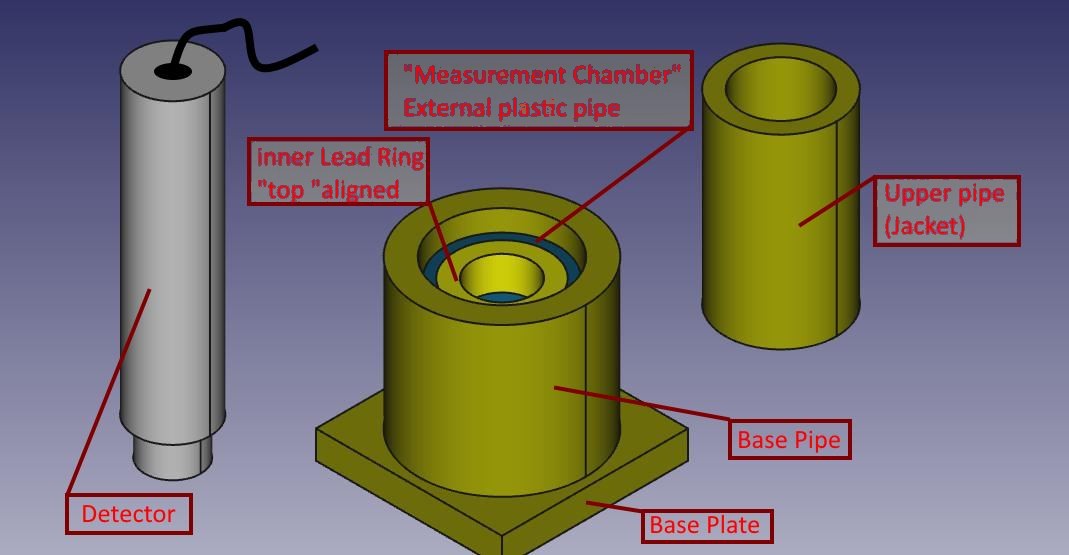
The measure consists of a base plate, plus some concentric cylinders, of various sizes and thicknesses. Among the components leaves something’ of slack, in order to facilitate the Assembly ’.
The material is actually brass lead, to distinguish it from the ’ probe grey aluminium, While the piece of inner cylinder (barely visible) is the unique ’ of plastic, with concentric ring in lead.
All the lead parts were made from sheet metal 1,5 mm thick, cut with a common Bill-sheet and shaped by hand, wrap around cylinders of aluminium/steel/plastic I had available (used only as “DIME”).
The base plate is made by folding several times a strip of sheet metal of equal width, getting a decent thickness.
Sheet bends easily around the straight edge of a table and flattens with hammer taps. The lead is very malleable.
All the pieces were wrapped with paper wide enough, so handle them does not come into direct contact with lead, that tends to get your hands dirty. Also why is good to calculate a little’ of slack between the various diameters of pieces, so then that paper coating doesn't break any insertion/extraction of cylinders all ’ same, that partially must fit one inside ’ more (as for the cylinder and top shirt)
To measure you follow this pattern:
- First arises on a table the base plate and the cylinder base;
- You insert the sample to be tested in the base tube, so that it touches the inside (lower) Dell ’ ring of the measuring Chamber: You can tuck under to it appropriate spacers;
- You put the measuring Chamber (plastic cylinder and lead supportive ring) so the below sample is centered on the bottom of ’ ring;
- He slips his shirt more than basic ’ inside the cylinder: It will support the plastic pipe and concentric ring of ’ will lead to the hole to allow subsequent insertion of the probe;
- You insert the probe : in my case straight draw in ’ ring of lead measuring nursery.
From the tests I've done this setup reduces background noise for almost 20 CPS to 3,1 CPS
Marco Russiani
Download this project, complete with more information and pictures:
![]() Theremino_Pozzetto_di_Misura_ITA.pdf
Theremino_Pozzetto_di_Misura_ITA.pdf
![]() Theremino_G-Ray_Test_Chamber_ENG.pdf
Theremino_G-Ray_Test_Chamber_ENG.pdf
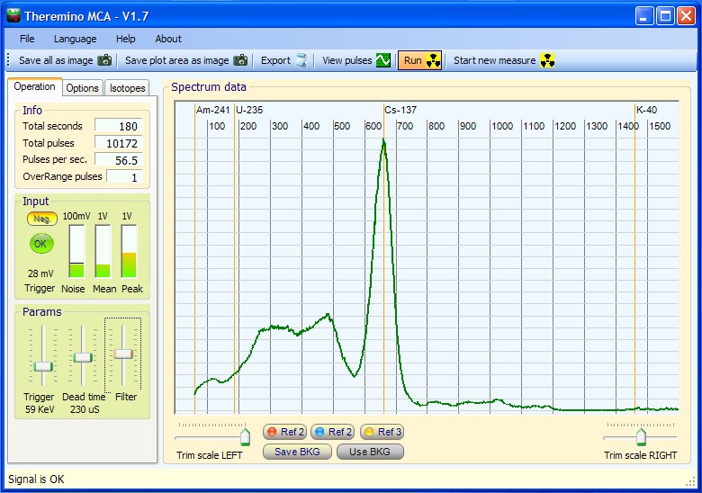
I leave a small contribution to someone who is just starting to use the program :
First thing you have to set the audio input level to minimize surges into the box “over range pulses”
We can set negative impulses with the appropriate button
Adjusting Noise should be just above the level (sets with the trigger)
The dead time must be adjusted in a manner that does not have “pileup” (depends on the width of the pulse) and should be checked with the oscilloscope.
The filter is used to have a chart softer and quickly see the result.
We can make an accurate measurement of the Fund save it for later use it as “Tara” It will be subtracted from the measured by the sample taking “outside” only the characteristic peaks.
And’ can also store a measure and hold it for comparison with “Ref1”
The control “Trim stairs Right” serves to compress or expand the spectrum and calibrate it on characteristic peaks and known samples used.
The control “Stair trim Left” need for transarlo right / left and should be used with the above command to adjust the scale.
Alessio, Thanks for the instructions that are very useful since, For now, the instructions associated with the program are minimal and that I don't know when we will have time to complete them.
Let me just add one important:
Some sound cards reverse the impulses as well as some signal adapters do. Why and’ difficult to be sure of the polarity’ of pulses. This is further complicated by the fact that some Oscilloscopes software and audio recorders, as “Intune” for example,, show the pulses with a polarity’ while others show them with the polarity’ to the contrary. All this and’ due to the fact that for an audio signal polarity’ It pulses’ important and that therefore there is no standard sure to define which’ the real polarity.
Therefore the key “Neg.” must be pressed or released with the following method:
– If the polarity’ and’ right across the spectrum moves to the right and the indicator “Peak” most salt’
– If the polarity’ and’ wrong the whole spectrum moves to the left and the indicator “Peak” doesn't move almost
Hello,
MCA looks like nice program. Downloaded both versions- with source and without source. Neither program will run. Error message says “failed to initialize”. I am using Win XP. Is that a problem?
Also, is source code available in VB6?
George
You should install “Dot Net 3.5 SP1” from:
http://www.microsoft.com/en-us/download/details.aspx?id=22
The source code is only in VbNet.
bye
Livio
Gentlemen,
Congratulations on designing this excellent gamma spectrometry software. I have tested it with my GS-1100A and I get very good results.
With your permission I would like to link my web site to your page.
Please advise if this is okay.
Best regards…
Steven Sesselmann
Yes, you can link our page.
Thanks for your appreciation, and sorry for some unfinished features,
in some days we plan to complete the 90% of the program.
Bye
Livio
Livio,
I have set up a page with a link back to here. Is this the best page to direct people for downloads?
Also let me know if you want me to mention any specific or unique features.
http://www.gammaspectacular.com/index.php?route=product/category&path=69_88
Steven
Thanks for your link.
Your text is OK. and the linked page also.
…maybe you can specify better the name of the program “Theremino MCA”
If for you is OK we can link your site here: https://www.theremino.com/contacts/references
Linux and Mac
————————————————-
About Mac and Linux versions you can write to our expert of “alien” systems: Roberto at development@theremino.com
Many of our software can work on Linux and Mac if installed properly:
https://www.theremino.com/downloads/linux
https://www.theremino.com/downloads/mac-osx
but my time is limited and I produce and test our software only for XP, Vista and Windows7 (32 and 64 bit)
I do not know what is “Crossover”, all the Theremino software uses the Mono system that is cross-platform on Linux and Mac
For my experience all our software when executed on Linux and Mac is not so efficient and stable as on Windows. Windows is always better for scientific usages.
If someone thinks to be able to do this on Linux or Mac, please do it, all our software is “Free”, “Open Source” and “Modular”
Maybe for Linux and mac users you can write on your page that they can write question to development@theremino.com
Bye
Livio
Theremino MCA is a great spectrometry program. I appreciated the time and effort your team have put into creating it, plus providing it to the community.
You have just updated it to version 2.4. There is more trim right in 2.4. The trim right scale setting maximum setting has increased from 900 to 1200.
I am using a windows vista laptop, works fine with PRA. Using the on board sound card with the mic/line in set at 96K. The maxim peak position I can get for Bismuth Bi-214 at present is 386 Kev with the 1200 trim right maxium setting.
I estimate it needs to have a maxium setting of at least 2000 for trim scale right to accommodate a lot of scintillators out there, to get peak calibration correct.
The maximum energy is 3200 Kev. To see also the high energy peaks you need to reduce the level of the audio signal by acting on the Windows audio mixer (please note that there are two mixer – Playback and Recording)
If the audio signal is too much the audio card cuts the high energy pulses and nothing can be done in software to correct this. Please follow the program indications “Increase the audio signal” and “Reduce the audio signal”
The audio mixer level is correct when:
– the program says “Signal OK” for the 99% of the time
– the peak meter is from 50% to 90%
I can see the high energy peaks clearly, it is just that the scaling in out. For example with the present maximum right trim in ThereminoMCA version 2.4, K40 is positioned at around 900 Kev.
If K-40 is at 900 KeV with the TrimRight at maximum then your audio signal is very little.
Please follow the program indications “Increase the audio signal”
To increase the audio signal you must open the Windows “recording” mixer
and increase the appropriate slider regulation.
The audio mixer level is correct when:
– the program says “Signal OK” for the 99% of the time
– the peak meter is from 50% to 90%
If you can not increase the signal beacause the Windows mixer is already at 100%, or because you can not find the “recording” mixer, please specify better your problem and we will find a solution.
In the future versions of ThereminoMCA maybe we will add a “Audio gain” control that will help you in this situation.
Bye
Livio
From: John Doe
To: geigercounterenthusiasts@yahoogroups.com ; GammaSpectrometry@yahoogroups.com
Sent: Sunday, November 04, 2012 10:19 PM
Subject: [GammaSpectrometry] Theremino test for busy people [2 Attachments]
Perfect!
———————————————-
Downloading : 30 second
Installation : 30 second
launching : immediate
connection of the probe : 60 second (I had to search my adapter in my desk)
Reading the documentation : 0
Setting and adjustment : 5mn (just push all the buttons randomly and check the screen)
acquisition and first result : less than 30 second
Total 10mn to see what takes hours with other software (see pictures)
Many thanks for this superb product!!!!
And he bonus is an excellent resolution and a good energy scale setting if your probe is linear.
Alain
Thanks for your good testing.
We are receiving many other tests useful for a good calibration.
Some videos here:
http://www.youtube.com/watch?v=P_WpkaLX0BQ
http://www.youtube.com/watch?v=r2l2vb0Xeok
I tested Theremino and I found it really easy to use.
I was not able to get sensible results from any other software as yet due to the learning curve and not having any working equipment to compare to.
At least I was able to get a plot right away with your application and as such this is a major milestone in my journey into Gamma Spectroscopy.
Curious if you have implemented the Isotope Identification feature yet. I found the Isotopes.txt file in the Extras sub directory and modified it but the application does not seem to be showing the isotopes I added.
Regards,
Allan
Thanks Alan for your contribute to our discussions and researches.
The “isotope identification” is not implemented now, and maybe we will not implement the raw “identification” and the associated semi-manual methods like the “area of interest”.
But we are studying a new method, similar to the “peak fitting” that, in our intentions, will be capable to identify the “signature” of the isotopes and then to accurately measure their relative abundance.
Please note the use of the word “relative”: when measuring radiations, the value measured depends from so many factors that there is not a “true” value. Beware of those who claim to deliver a absolute value!
Please wait some time, in the future versions of ThereminoMCA we will implement also the “Baseline restoring” that is very important in order to clean the peaks, reduce the noise and to speed-up the graph creation.
Bye,
Livio
Hi Theremino team,
I made little changes in your code “Isotope identifier”.
Source, builded application and short documentation I sent you on mail.
I hope that I gave little contribution to make this application better.
In the future I’ll give all I can to help you with improvements.
Please let me know if this is Ok.
Tom 9A5TOM
So, gmail blocked mail and I needed to delete file Theremino_MCA.exe
from folders:
\Theremino_MCA_V2.4_WithSources_new_ver_TomyThereminoMCA
\Theremino_MCA_V2.4_WithSources_new_ver_Tomyobjx86Release
I sent it again.
After you build/rebuild your solution you’ll get it again.
Tomy 9A5TOM
The best method to send files is to use 7zip (or rar)
Normally we use 7zip that is freeware and a very good software!
Hi Livio,
I sent new version wiht multiresults isotope identification for exact energy and close to energy.
Second change is selective marking of exact isotope energies markers for comparison and calibration.
Hope it will be useful in one of the next version of application.
Tomy
Because we have not the time to merge the new versions every day, we will include in the distributions your versions.
Then, when all the experiments will become more stable we will do a final merging.
Bye and a great thank for your help.
Livio
Just carried out a comparison test between PRA and Theremino, using an identical setup. same volume same detector, same sample rate 192khz etc. The only difference was a switch of software. The resulting spectrum from PRA showed sharper peaks and better resolution at 662 Kev.
Ok for same volume same detector, same sample rate 192khz etc.
But why not to mention the aquisition times?
And why not to say that at low energies the opposite happens?
In other words: it is easy to add some resolution by removing 99% of good samples, but this increases so much the acquisition time that the system becomes not-useful.
In order to get good resolution in useful time it is not a good idea to remove samples like PRA does, but it is better to use a low noise power supply and a good pulse shaping.
Many tests have shown that the row enlargement takes place only in case of very noisy signal. To be more specific: in case of signal from CCFL type power supply with a frequency of about 3 KHz (thus very low and hardly filterable)
The only method to get a low noise signal is to use a power supply working at high switching frequency (more than 100KHz)
In addition the pulse shaping circuit must generate pulses with a long rise time (> 50uS)
If the pulses are not shaped correctly a strong “ringing” is produced and the peaks are enlarged.
Thanks,
The new Audio Gain feature in Theremino MCA 2.6 fixed my peak position issue.
I also like the fact that it now has an isotope identifier built in. For this to be really useful you need to have a lot of accuracy in the peak positioning in the chart.
One suggestion I would make is that a lot of PMT in scintillators have non linearities that affect energy scaling. In other words you need an exponential adjustment to compensate for this.
You can correct for this in PRA by using the following procedure. This adjustment info was provide by Steven of Gamma Spectacular.
You can correct for this, if you record a spectrum with three known peaks, then export the data into excel, where you can create a new calculated column with a small additional exponential factor.
So you have three adjustment numbers in the function.
1) The multiplier (X) – this sets the gradient of the function
2) The konstant (K) – this sets the height on the Y axis
3) The exponent (and) – this number creates the curvature in the function
Energy = (((arb.units) * X)^e) + K
Peter
The isotope identifier is based on a preliminar work of Tomy (9A5TOM) and is not well tested by us.
We will not do a “Identifier” but we are making a good “Peak Fitting” algorithm.
But, as you correctly write, before to start with the Peak Fitting, we need to test, linearize and improve many things.
We are making researches on the non-linearity sources and thanks for the PRA formula that seems to be an improvement of the formula used in the PRA 5: Energy = arb.units * X + K
We think that the new formula Energy = ( arb.units * X ) ^ e + K (removed unnecessary parentesis)
is a little better than the old formula but we are trying to do better (maybe with a “spline” or with a interpolated “lookup table”)
The ” + K ” is shurely an error because it translates ALL to the left and produces negative energies that are not-real.
—————————
Please wait some time, we will do this in the best possible way.
If you can help with other formulas or ideas please do it, we appreciate your contribution, thanks.
bye
Livio
Sto giocando col baseline restoring.
Ho visto il quadratino intorno al picco che si allarga in funzione del cambio dei parametri.
What do you mean exactly with baseline restoring?
I change much the graph , with or without this function
The Baseline Restoring helps signals with the zero line unstable.
In the pause between an impulse and the other the audio signal should be zero but, for many reasons, almost all hardware to produce spectrometry signals with the zero line dancing continuously up and down a few millivolts compared to zero.
Usually when the pulses are very frequent zero-voltage drops and vice versa.
A zero-voltage unstable produces a widening of the rows and this effect and’ greater for low-energy lines that, being small, are very influenced by baseline on which rest.
To see the effect of Baseline Restoring
——————————————————————————————————-
– Open the impulses and sets only display energies 50 to 120 Kev
– in these conditions you'll see that:
– without BaseLineRestoring the zero line rises and falls slightly’
– with BLR the zero line is stabilized
Only if you're looking at small pulse you can see the beneficial effect of stabilization, because’ a few dozen mV on a small signal are significant and visible, While compared with pulses from 1 Volts are irrelevant and also too small to see their displacement effect.
The beneficial effect on the graph it’ very low energy and also you will only notice if not perfectly adjusted to the type of signal and noise in your probe can’ also worsen the graph. So if you're not sure and’ better keep it disabled.
The two regulations are the position and width of the area where the signal is sampled. This area must stand before the impulse, before the ringing, but not too far away and big enough to integrate the noise well and stabilize the best baseline.
Min and Max settings KeV pulse Viewer
——————————————————————————————————-
Regulations are useful for controlling the signal. Allow you to see only the pulses that are recognized in a certain range of energies. This turns the small analyser into a powerful SCA Analyzer (Single Channel Analyzer) and lets see signal behaviors and flaws very infrequent and so invisible to an ordinary oscilloscope.
These regulations affect only inside the oscilloscope so you can leave used them as they are. Do not affect the graph.
Let's see if I give you a correct answer , the function is used to correct the move up/down pulse , If you open the oscilloscope show the blue square that samples the initial part of the pulse(before the ringing) well the program does nothing but rank the impulse on the zero line.
Of course the phenomenon of displacement occurs more readily with the lower energies because very close to noise.
If you put in the parameters min max Energy and Energy two very low values as min 10 Max 60 You'll see that the signal line rises and falls very , the basic command line restoring corrects that basically keeps tight impulses otherwise with that very wide swing would see them.
With the command position move the sampling point right/sinistra and size the spread (in amplitude) These two parameters you need to best find the sampling point talking too far nor too close to the “ringing”, you have to try to put it where at least 3/4 such oscillations’ He corrects effectively.
Ok thank you. I have seen great improvements. In theory you should see improvements on peaks at great energy but I don't , Indeed it seems to me that they ' fan ' out. I thought today it wouldn't hurt a logarithmic scale of energy to compensate for the fact that in any probe naTl broadens your impulses with increasing intensity value (in practice it is inconsistent at high energies) It would help a lot to find eye impulses
Baseline Restoring.
————————————————————————————————-
You're absolutely right also I have seen that there are improvements, but I'm sure at low energies should be no. Probably there’ still an error in the algorithm…
Please everyone be patient, do these tests is time consuming and parts yet to be put in place are many.
I would recommend, For now, by leave off the BaseLine Restoring.
Horizontal scale logarithmic.
————————————————————————————————-
It might be a good idea, indeed great, could increase the high energy level and compact the bins that are now far scattered into something much more’ visible and recognizable. Also the area of the lower energies, What time and’ very compressed, would be expanded! Audio spectrum analyzers also have the logarithmic frequency scale.
I sure hope that it works as we imagine and will try it as soon as possible.
Thanks for the advice.
It is possible to correct a floating baseline software?
(Baseline correction not working)
"I don't think PRA drops all the pulses, I think all pulses are normalised first.
If no other method will work then we will implement the "Shape Recognition" (It is simple because in the right place we have all the necessary data)
But before to do this we will try any other method non involving a raw pulse decimation.
Shape recognition
——————————————————————————————————————————–
We do not know if PRA corrects the baseline shift, because the sources are closed.
But we have noticed this:
– if not using the “shape tolerance” the PRA data are so noisy to be unuseful
– to produce good results the shape “tolerance” must be a little number
– using a little “shape tolerance” the drawing speed is slowed
So we think that the PRA method is to remove pulses.
Solutions
——————————————————————————————————————————–
We have tested the “baseline correction” algorithm but it not works as we hoped.
We are triying many algorithms and i am shure that we will find a good software solution
also for the floating baseline.
bye
Livio
Amazing performance via a simple sound card and Theremino software — congratulations all around. If someone had asked me if this were possible, I would have said, no, not really. Of course, I would have seriously underestimated the ingenuity of those who come from the land of the great Enrico Fermi….. RANDALL
A comparison made by Spectacular Range: http://www.facebook.com/pages/Gamma-Spectacular/146649762066972 showed that the FWHM of PRA (8.7%) was better than Theremino 2.6 (11. 2%) so’ We've been busy and now the FWHM of the version 2.8 and’ come down to the incredible 7.2%. that you can’ see in the images on this page: https://www.theremino.com/blog/gamma-spectrometry/images
Thank you Steven Sesselmann which she promptly sent the audio files needed to solve this problem. And we cannot thank enough not Marek Dolleyser that, with its PRA, paved the way for all of this.
I'm testing the 2.9 version. Interesting the feature to automatically calculate the Fwhm. I could see my halfgood probe is 13% While my best is 8.2. If I use the baseline restoring oprion , it drop down to 7.2. Nice feature. The low energy treshold can be lowered to 0 kev with no pileup . The lower 31 kev peak is very small but don’t know if it is partially cleaned or it is partially deleted. . Very nice result. Have fun
Sono capitato per caso sul vostro sito.
Incuriosito, ho scaricato Theremino MCA v. 2.7.
Subito andato a bomba. Surclassa PRA che sto usando da mesi.
Facile, velocissimo, accurate. Ora ho messo sotto il torchio la versione 2.9. Sembra un ulteriore deciso miglioramento. Vi saprò dire.
Per ora complimenti e andate avanti.
Ci sentiremo preso. Antonio
I’m testing now the 2.10 from Tomy. I could use the baseline r option and works great reducing noise at low energy. Livio , I suggest you to include the Tomy modify as they are really nice and nicely working.
I am working to integrate the Tomy Identifier in the main program… but today is a very difficult day – everyone phones here.
Maybe i can finish (with some bug) before 21.00
Bye to all.
Livio
The Tomy Identifier is now integrated in the “Tools” menu (with some little bug)
PRA 4.4.1 verses Theremino MCA 2.12
See the PRA and Theremino rain swab test charts showing significant Radon decay daughter isotopes captured from the edge of a storm, here on the east coast of Australia, on the evening of the 17th. This test was done using PRA and Theremino MCA software, running on the same computer at the same time. Audio setting was set at 96K sampling.
There are a couple small peaks that appear in both software charts that could indicated the presents of a small amount of U-235, plus there is also another peak to the left of the Bi-214 peak that maybe Beryllium Be-7. Won’t know for sure until I retest in a few days.
http://sccc.org.au/wp-content/uploads/2012/11/Rain-Swab-4x-17.11.12-PRA-9hrs.jpg
http://sccc.org.au/wp-content/uploads/2012/11/Rain-swab-4x-171112-T-9hrs.jpg
The lower chart in the Theremino V2.12 screen capture is a reference after the first 15 minutes of testing, and the higher chart is after 9hrs. The Pra V4.4.1 chart is also after 9 hours.
PRA is still seems to have better resolution at lower keV energies than Theremino. Theremino is very quick at showing the main peak energies, and magnifying the higher energy peaks using the Energy Compensation feature.
Thanks for this good test!
For the future test I can suggest little improvements:
– to save always a complete image with all the controls visible
(so it will be possible to see the test conditions)
– to use the baseline correction that (if correctly trimmed) increases greatly the resolution
As a good starting point use:
– 50 and 50 in the BaselineCorrection
– 250 uS for the DeadTime
Do not change this values before to test them, use 50, 50 and 250 and see that the resolution is increased.
If 50,50,250 does not increase the resolution then, please, send to us the audio file (or specify a test audio file if already present in the test file list)
bye
Livio
Some users suggested to find a good method to isolate from noise the net peak area.
This is needed to:
– count pulses in the peak area
– calculate a significative FWHM also for little pulses, on a high noise floor
We will try to do this with some different methods and some time will be needed
for the selection and the final approvation of the best method.
Now this problem is in the ToDo list because we are in the middle
of a drastical revolution of the program, and we can not publish it.
The next version (V 3.0) will introduce many important features:
– “Graphical Equalizers” for Energy Linearization and Amplitude Compensation
– Automatic Linearization and Compensation
– Selectable logaritmic scales for X and Y axis
– Audio Input modified to work normally not with 0dB, but with -10dB audio level
(this avoids to work near to the audio card saturation zone)
– Ability to work well also very low audio signals
– All the controls reorganized with the most important controls over the first tab
– Docking of the Pulse-Shape-Window and Equalizer-Window
– Ability to decrease the refresh time for slow systems (Linux…)
– Bin numer in the XRF area ten times increased
bye
Livio
Volevo ringraziarvi pubblicamente da parte mia e da parte delle numerose persone che hanno assistito ieri ai miei percorsi Didattici.
In totale hanno assistito più 100 persone in 4 sessioni di laboratorio che ho fatto al “Festival of things unseen” by Montelupo F.no a number above expectations, I had words of praise and congratulations for the’ work of spreading , but above all the congratulations for the work done by the team Theremino regarding multi-channel Analyzer.
a greeting ,Alessio.
I would like to know at what stage of development is the PMT Adapter
and if it is at least available a wiring diagram of the same
Kind regards
Fiorenzo
The PMT adapter is working on 90% of our time… We're trying to get the lowest noise, a perfect bipolar pulse does not lead to confusion in the base voltage, the minimum power consumption, maximum temperature stability and even using a few components, easy to find.
Putting together these features is a long job, Anyone wishing to help in searches could download the current project from here: https://www.theremino.com/files/PMT_Adapter.zip
This is a project “Eagle” and simulations “LTSpice”, in the folder “Images” the main files are visible without installing anything.
In these last days we made changes to better stabilize the feedback loop but you can only see by installing PSpice and opening the file: “Alim_FixedFreq_6.asc”.
Without these changes may occur:
– “hops” especially when setting low voltages (under 700 Volts)
– sudden “jumps” present at the change of temperature also tens of volts
– chunk of the oscillator at high voltages (power cycle)
The consumption in all cases is around 30..50 but the noise should be less than the Volt peak to peak (but attention to the connections with the audio and power tab, If entering from a microphone input, add a resistor from 12 k in series at the entrance and near the entrance “MIC” or in the sound card)
Should also raise the two filter resistors R5 and R6 from 100 k to 1Mega, This slightly lowers the voltage on the tube (twenty volts) but otherwise has nothing but benefits.
We got the best functioning of the PMT (a HAMAMATSU R6095) and a perfect linearity’ of response, with 11 resistors 10 Mega among the dynodes, 1 resistor from 1 Mega between the last dynode and anode and a 4.7 nF capacitor 10nF or between the last dynode and mass.
Here is an outline to text format…
Cathode-10 m-DY1 DY2 DY3-10 m-10 m-10 m-10 m-10 m-DY4 DY5----DY6 DY7 DY8-10 m-10 m-10 m-10 m-10 m-DY9-1 m-DY10-DY11---Anode
– capacitor 10nF 1500Volt between cathode and DY11
– shielded and down PMT-BNC Adapter, negative at the cathode, positive to anode
This circuit behaves better than lying around these days but still has some flaws. We recommend this version only to those who have knowledge, time and equipment to help us put it in point. For all the others and’ better to wait until the end of our research.
For the brave who want to try it “as it is”. Good luck…
Livio
How do you see ' Alim_FixedFreq_6.asc’ in PSpice?
I PSpice 9.1 student edition
Thank you
Fiorenzo
It’ made for PSpice but for LTspice and do not think it can import it in PSpice and anyway you'd lose all the components that I did etc…
Install LTspice is extremely light and you will see that it is super fast, simple and complete, and then unlike PSpice is free for all, not only for children.
If in the future you will need component libraries for LTspice chiedimele…
Hello
Livio
If you settle for a picture, download this: https://www.theremino.com/files/PmtAdapter_FixedFreq_6.png
and save to install LTspice (but I would recommend the same to do so, before LTspice I used all the others and I can assure you there is no comparison – you got to know him a little’ because at the beginning it seems too simple – I had discarded it for this – but I was wrong about ugly)
Many friends call us to find out you need to go , Here's what I decided to use some answers given by email and make a small HOWTO.
Hardware :
Photomultiplier tube should have a minimum diameter of 25 mm smaller are not very usable.
You can find them used on ebay , I recommend that we use ourselves in research group Theremino: “Hamamatsu-PHOTOMULTIPLIER-TUBE-R6095”
Crystal scintillator :
the ideal would be a sodium iodide doped thallium “NaI(TI)” diameter suitable to be coupled to the tube to fear present that are very hygroscopic so are sealed in an aluminum casing has a transparent window (glass) the side that has to be coupled to the tube , to avoid those showing signs of yellowing index that the seal is gone.
The alternative are crystals BGO (non hygroscopic) Csi(NA) , These sensors have all three light output around 400 NM suitable for tubes with photocathode Biolkali, plastic crystals are very common on ebay but they are not suitable for making gamma spectrometry.
On ebay there are (NaI(TI)) former USSR have very high prices for glass facts 30 years ago I say I preferred to order a new one with the same price (€ 140) I took a 25 X 25 mm NaI(TI) certified by 100 to 1000 Kev.
Consider that most often is the Crystal the more sensitive reading high energies and more costs.
Feeder :
You need a power supply with low ripple , shielded and suitable as voltage and current recommended pipe works with maximum voltage of 1500 V I’ the food between 650 and 750 V because the Crystal is very bright.
We are preparing a Kit of a power supply suitable for powering the most common tubes , with a built-in preamplifier “spreads” the pulses produced by the pipe and which with discreet efficiency from a standard PC sound card.
The cost of the Kit you should get around on 30 Euro , for those who wanted it ready to use you could achieve it by agreeing on the mounting.
Otherwise you can buy ready here:
http://www.ebay.it/itm/GS-1100A2-USB-HV-Bias-Driver-for-Scintillation-Detector-/170702786085?pt=AU_B_I_Electrical_Test_Equipment&hash=item27beadce25&_uhb=1#ht_1730wt_954
Software:
is open source free download here :
https://www.theremino.com/downloads/radioactivity
IMPORTANT, We are working continuously to improve it and make it more accurate and reliable as possible , It is useful, therefore, constantly follow developments through various blogs below.
https://www.theremino.com/blog/gamma-spectrometry
https://www.theremino.com/blog/gamma-spectrometry/signal-filters
https://www.theremino.com/blog/gamma-spectrometry/linearizations
https://www.theremino.com/blog/gamma-spectrometry/identification
to use it without any hardware you can’ use some audio files available here :
https://www.theremino.com/blog/gamma-spectrometry/audio-files
of course any contribution is welcome , We are developing this project with many enthusiasts and professionals internationally ,Anyone who wants to participate we'd love to.
Happy Gamma spectrometry , Alessio.
I'm interested on your described Theremino_PmtAdapter. Where and when is this device available?
Thanks
Roland
We will not build the adapter because we are a “non profit” organization but you can call Alessio that will compose some kits for the friends.
Some test versions of the PMT adapter are working in my laboratory with outstanding performances ( voltage from 550 to 1100, good pulse shaping, good stability, noise 200uV ! )
But unfortunately there are problems that we must correct before to release a reproducible version.
1) the current consumption is too high ( 90 but at 1100 Volts )
2) the high voltage transistor is difficult to find, so we are trying to substitute it with a mosfet (maybe a BSP300 – we will test it as soon as available)
3) in some situations (output short circuit) the circuit shuts down and the power must be removed to restart it
So, please, consider the:
https://www.theremino.com/files/PMT_Adapter.zip
https://www.theremino.com/files/PmtAdapter_FixedFreq_6.png
only as a good starting point…
I think that we can conclude experimentations in some weeks, for now you can call Alessio ( ik5pwr-AT-inwind.it ) and reserve one of the first kits.
bye
Livio
You can see our last version M2 (M2 means: the second version with the mosfet BSP300) in the following files:
Schematics: https://www.theremino.com/files/Alim_FixedFreq_M2.png
LTSpice simulation: https://www.theremino.com/files/Alim_FixedFreq_M2.asc
In order to use LTSpice with our circuits you must download our libraries and follow the instructions at the and of this page:
Italian: https://www.theremino.com/downloads/uncategorized
English: https://www.theremino.com/en/downloads/uncategorized
bye
Livio
Appena provato Theremino MCA 3.6.
Finora nessun problema rilevato. Il linealizzatore ha perfettamente messo in riga anche un tubo che mi ha sempre creato problemi.
Complimenti e buon lavoro.
Antonio
Grazie del commento! Sapere che il linearizzatore funziona bene ci fa davvero molto felici.
In molti ci avevano sconsigliato di usare questo metodo, sostenendo che equalizzare punti precisi, come il PRA, fosse meglio…
Theremino PMT adapter is ready for first February week.
There are three options :
first one Only bare PCB
Second Complete kit (PCB and components)
Third PMT adapter ready to use with USB audio sound card modified for easy connect to PC
if anyone are interest please contact me at alessio.giusti@meteolink.it
Nel kit completo i componenti smd sono gia montati o da montare?
Thank you
Fiorenzo
Il kit è composto da Circuito stampato e componenti (SMD e tradizionali) tutti da montare
I am interested in the BGO and PMT used to obtain thee signals. Do you have any data and information on the sensor and hardware.
Is the theremino performing an A/D signal anaylsis from the PMT?
About spectrometry sensors and hardware you can read the following pages:
https://www.theremino.com/blog/gamma-spectrometry (this page)
https://www.theremino.com/downloads/radioactivity (the download page)
https://www.theremino.com/video-and-images
And to download the ThereminoMCA and ThereminoGeiger from here:
https://www.theremino.com/downloads/radioactivity
https://www.theremino.com/wp-content/uploads/2012/11/ThereminoMCA_V4.5.zip
https://www.theremino.com/wp-content/uploads/2012/11/Theremino_Geiger_V4.6.zip
In the downloaded files you will find many useful documentation files in the “DOC” folders.
Mainly the files:
“PmtAdapters_ENG.pdf”
“ThereminoMCA_Help_ENG.pdf”
After downloading the software you can also test it “without any hardware” and also explore the documentation files using the application menu.
About the ADC
Yes, we use a 16-bit ADC, much better than the usual MCA hardware ADC
The audio ADC are internally oversampled and provide more than 100dB of dynamic. So they do not require the “Sliding scale” methods needed from the hardware MCA, because the steps (and thus the “bins”) are already very narrow.
In addition, with our software the usual costly zero ADC adjustments and the “zero-pole” compensations are not necessary, making the whole system simple and inexpensive.
Can I use a not stabilized power supply?
Can I use a negative power supply?
Why do not use a microcontroller A/D converter to read the PMT signal?