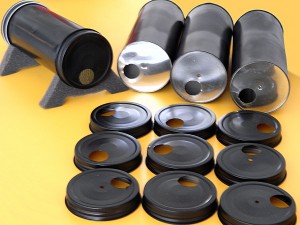
A room at ions for radon
This room is used to measure ion "continue" radon. The advantages of this solution are the low cost, the speed of measurement (a precise test in half an hour), the measure "continue" and won't bind to collection and measurement but does everything automatically and finally, ease of adjustment (the calibration depends almost exclusively on the geometrical dimensions of the device and is not affected by temperature, humidity and air pressure)
Version 7 – Year 2021
This version contains all the experience gained over the past years, so it is considerably more stable and also easier to build than the previous ones.
New projects are posted here:
https://www.theremino.com/blog/geigers-and-ionchambers/ionchamber-improvements#version7
For more information, please read the documentation for the application Geiger and previous versions of the ion Chamber.
Version 6 – Year 2016
The room was again improved ion. We added a resistor between Gate and mass, to stabilize the voltage of the FET with very humid air (stable measurement up to 70% humidity and over). And we have increased the stabilization, both the amplifier circuit, that in the high voltage generator.
New projects are posted here:
https://www.theremino.com/blog/geigers-and-ionchambers/ionchamber-improvements#preversion6
The discussion on measuring units "concentration" and "activity" is here:
https://www.theremino.com/blog/geigers-and-ionchambers/ionchamber-improvements#concentration
For more information, please read the documentation for the application Geiger and previous versions of the ion Chamber.
Version 3
The latest on electronics, be accessed directly here on the site:
Radon_IonChamber_Electronics_ITA
Radon_IonChamber_Electronics_ENG
All documentation in PDF format:
https://www.theremino.com/files/Theremino_IonChamber_Pdf-Docs_V3.zip
Eagle PCB project, the 3D images and simulation files for LTSpice:
https://www.theremino.com/files/Theremino_IonChamber_PCB_And_Simulations_V3.zip
The original file in ODT format (OpenOffice), for translators:
https://www.theremino.com/files/Theremino_IonChamber_ODT-Docs-ENG-JPN-ESP_V3.zip
– – – – – – –
The features are exactly the same of the DIY version, but the vibration resistance and weather resistance is increased. The Center electrode is no longer a thread (that can vibrate) but a stiff rod 2 mm, solidly fastened with insulators. The outer casing is made of steel 316, that not only is unaffected by vibration, but you would go over with a car.
This version can also be certified. For more information contact Carman, and the firm LACERC.
– – – – – – –
Alessio kit for the ion Chamber
Alessio writes:
“Tonight (24 11 2013 n.d.r.) I completed some Radon detector KIT, for those who have difficulties in finding the materials can supply I priced from friends and associates. I have also provided a "light" version of the Theremino Master, with only one entrance to speed Assembly and break down some euros. Monday, I'll hear a company to supply cylindrical tinplate canisters, so we can take a complete KIT also of mechanics”
For more information write to: alessio.giusti@meteolink.it
– – – – – – –
Notes for self-builders
The room is now well proven, dozens of specimens are in operation worldwide and all feedback has been positive. We do not yet have a calibration coefficient to be distributed. The comparison is made by comparison with professional equipment but, For now, We haven't found anyone who has one suitable. Make comparisons with lenses like the “Safety Siren” or the “tests from 24 hours” It's like not to make them, because radon also changes of 300% in a few hours. Alternatively, it would take a sealed Chamber with constant radon content, But even this doesn't seem helpful in research institutes. For now the best estimate of the calibration coefficient is as follows:
Sens. CPM/pCi/l = 2.20
Background CPM = 0.00
Dead time uSec = 5000
Connect the camera to any ion Counter type Master pin (no need to Search). So only one Master you can connect a Geiger and up to 5 ion Chambers.
– – – – – – –
Here you see the meter online Alessio (not always active)
 http://www.meteolink.it/radon.html
 http://www.meteolink.it/enradon.html
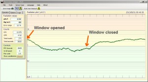
And two graphics of a room of Alessio with window closed and open
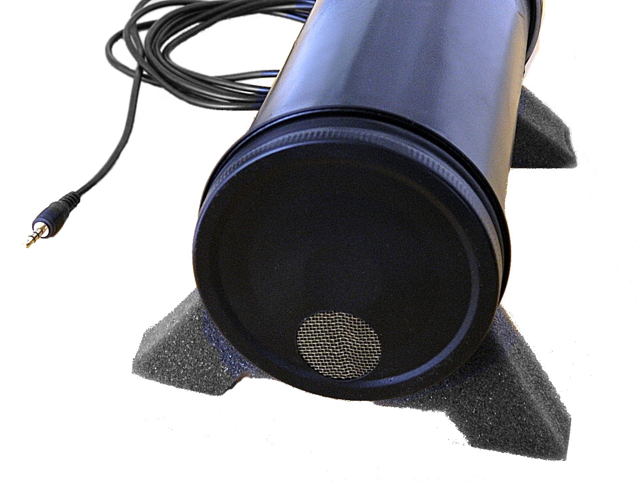
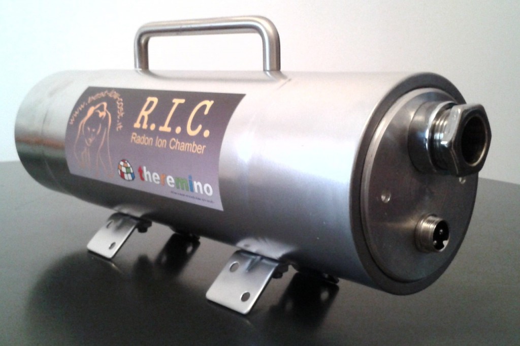
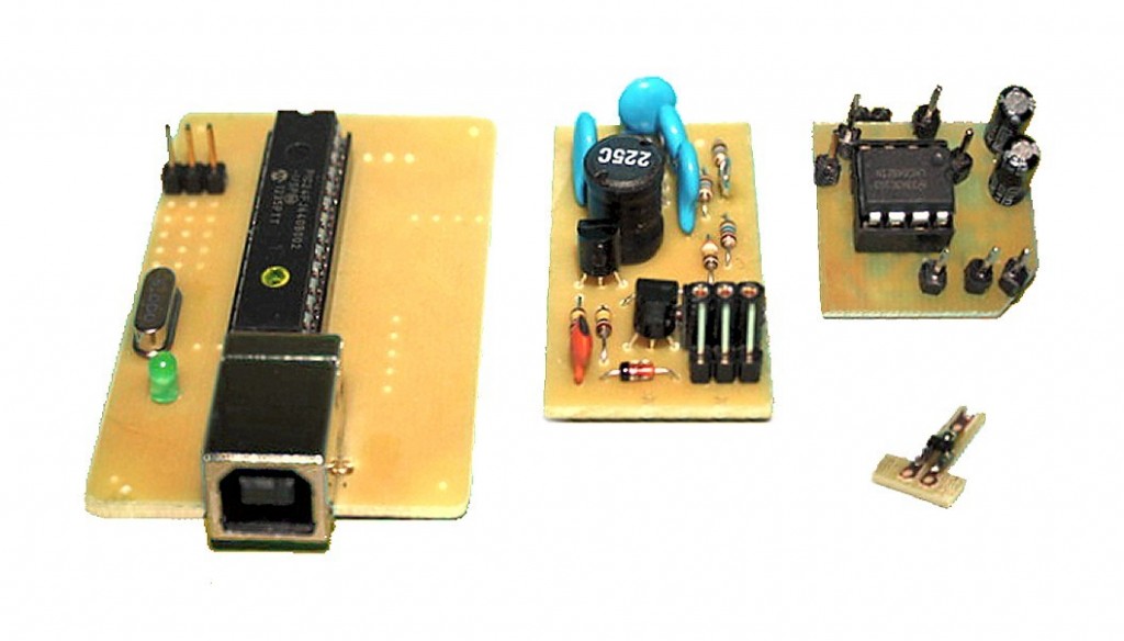
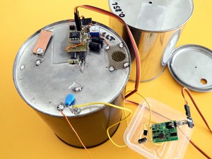
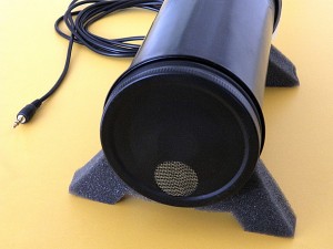
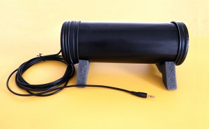
Below are some pictures of rooms at ions used in the tests.
... in final version
... and in preparation
Geiger tube radiation sensors
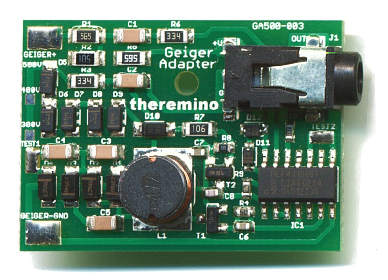
The GeigerAdapter is the link between all the usual Russian or American production requiring geiger tubes from 300 to 550 volts of power and standard signals of the system Theremino.
Geiger Adapter (power supply and signal adapter)
These adapters to geiger tubes produce a standard output signal, compatible with the inputs of type Counter (only for low levels of radiation) or rather FastCounter which works well at all levels, up to the maximum measurable with geiger tubes.
The supply voltage can vary between 3.5 volts and 6 volts. The power consumption is about 10 au with normal radiation levels (around 0.1 micro Sievert per hour) and grows to 6 but when radiation is equal to the maximum measurable with geiger tubes. (about 10 Milli Sievert) High voltages are present as this module is perfectly safe, his current limitation at 25 micro amps is so effective that can be touched with bare hands at any point without danger and without feeling the slightest feeling of annoyance.
The size of the GeigerAdapter are: 26 x 36 mm (SMD version). For information about components for the GeigerAdapter consult: www.theremino.com/contacts/producers
There are three versions of Geiger Adapter, the schematics and datasheets can be found here:
https://www.theremino.com/technical/schematics#geigeradapter
https://www.theremino.com/technical/schematics#geigeradapterdiy
https://www.theremino.com/technical/schematics#flintstones
Connect the Master Geiger Adapters
The Geiger Adapter connect to a Master Pin (or of a Slave) configured as FastCounter. To connect them in the laboratory using extension cords male female, no screens, that you normally use for all links in the system Theremino. If required you can connect multiple extension cords from 60 centimeters in series and get up to a few meters away.
Long links
For longer distances you have to use a shielded cable. Microphone cables with two wires red and white interior, are great, are robust and have the tear-resistant rope. Maximum shielded cable length is 500 meters and beyond (provided you follow the following guidelines).
With long connections you should use GeigerAdapters with low output impedance and an end-of-line resistor to protect Theremino Pin from overvoltage.
1) About Geiger Adapter SMD version, bridging the R10 from 33k or saldarci over a second resistor from 1 kohm (for the Geiger Adapters “DIY” and “Flintstones” This variation is not required because they already have a low output impedance).
2) Add a 100 k resistor in series with the signal wire, at the end of cable, within a few centimeters from the Master. Attention: These resistors from 100 k you bring only on pins configured as Input (ADC, DigIn and similar). You do not need to add resistors to Output Pin, or even worse to the serial line, connecting the Master with the Slaves.
3) Remember to do not attach non-Pin SMD modified Geiger Adapters additional resistor 100 k (that happens by mistake doesn't break anything but the 5 volt voltage, limited current not the resistor, may cause frequent loss of USB communication)
4) Avoid routing the cable in the same pipes (or cable ducts) electric plantor. Avoid strokes outdoors on flying spans or on poles. The strokes outdoors must be protected with grounded metal pipes and masonry. The areas that should be on top, for example on a roof, must be protected from the Sun with canopies (many geiger tubes over the 50 grades go crazy). Metal sheds should be grounded for Lightning.
See also the sample images on this page: technical/connection-cables * long
The Checker – A micro Geiger to keep in your Pocket
This micro-geiger used to go around and look for objects and radioactive minerals. The complete set of drums, buzzer, flashing led, Geigeradapter and Geiger tube can stay comfortably in a shirt pocket.
You can link the same probes (Geiger tube + Geiger Adapter) that are used for precise measurements in the laboratory with the application ThereminoGeiger. Detaches the probe from Theremino Master and connects to Theremino Checker, that provides the 5 Volt required, starting from a stack from 1.5 Volts.
The operation is completely analog (led and sound) and you can even add a ratemeter with analog instrument should have to measure the CPM in six steps. Then you get a device much like a ratemeter Ludlum with traditional scales x 1, x 10, x 100 and x 1000 and with three courses of integration by 20 Seconds, 2 minutes and 30 minutes. The features are even better than the old analog geiger, linearity and accuracy are absolute (best of 0.8% in all ranges), size and consumption are minimal and you use one battery from 1.5 Volts.
The circuit board is the same size as the battery holder (behind the PCB) for a single battery from 1.5 Volt AAA. The consumption is less than 30 UA whereby the battery takes about 3 years continuously (800 Ma/h divided by 30 UA = 26000 hours = 3 years). If you use only LEDs do not have the problem of sounds and you might as well leave it turned on.
For those who prefer a handset with digital measurement, output is available to connect an Android SmartPhone, with the free software PocketGeiger, or an iPad or iPhone with Ios7 and with GeigerBot software, free too.
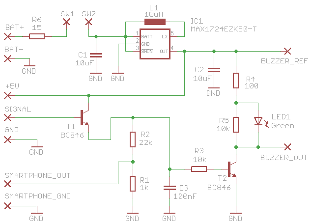
ATTENTION: The resistor R6 serves as protection against short circuits. If the battery has a high internal resistance, the checker might have trouble starting, and failing to reach the 5 Volts, It would consume much more power than they should (In addition 50 but instead of 30 UA). To avoid it you could replace the resistor R6 with one from 4.7 ohm resistor. With this change in case of short circuits the resistor would burn, you will then need to consider a fuse.
INCREASE THE LED LIGHT AND THE INTENSITY OF SOUND: To consume little and holding the stack up to three years of continuous operation, This circuit provides a buzzer and an led high efficiency. To use inefficient LEDs and BUZZER (But accepting a battery life of up to one year), You can use the following values: R1 = 22k / R2 = 220k / C3 = 100nF (or at least until 220nF) / Q1 = BC547C / Q2 = BC547C (Transistors must be with extension “C”, that means a gain from 500 to 600).
CONNECT SMARTPHONES: Some cellphones emit about two volts to power an eventual electret microphone. This tension can turn on the LED. If they do add a 100nF capacitor in series with R2 (cut the track between R1 and R2).
This compressed file contains the complete project Eagle, electrical simulation to ASC format to LTSpice, 3D images, schematic and Gcode to mill the PCB: CheckerV3
The Ratemeter – Measure in CPM
How much smaller than a Ludlum M3 this tool is no longer in my shirt pocket so you plan to connect it to the Checker only in some cases. There are no batteries and is fed directly from the checker through mini-jack.
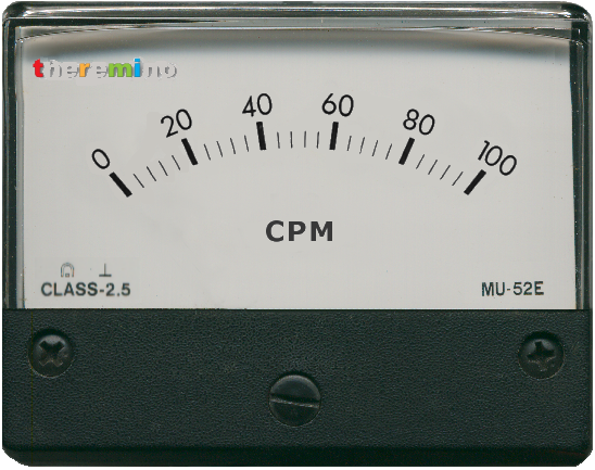
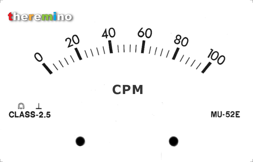
This is the scale to print and put in the analog instrument should have.
In this scheme are shown BC587 transistors, that are not easily. Instead you can use BC556 or BC557, or any other small PNP, I have a current gain (HFE minimum), of at least 100.
The ratemeter is extremely linear circuit, the impulses received from geiger tubes are elongated and reversed by TLC555, and come out with a constant width of approximately 350 uS. Finally, through a precise current generator, the pulses are loading a RC network connected to terminals SW1 and SW2.
The impulses coming from the Geiger must be positive and wide 10 to 250 uS (the impulses of Geiger tubes are always in this range).
If you use a signal generator for calibration, you have to prepare it to generate positive impulses from 100 us about. To calibrate the courses you will be using the following frequencies:
- “x 1-slow” – Full scale = 100 CPM – Frequency = 1.666 Hz
- “x 1-mid” – Full scale = 100 CPM – Frequency = 1.666 Hz
- “x 1-fast” – Full scale = 100 CPM – Frequency = 1.666 Hz
- “x 10” – Full scale = 1000 CPM – Frequency = 16.66 Hz
- “x 100” – Full scale = 10 000 CPM – Frequency = 166.6 Hz
- “x 1000” – Full scale = 100 000 CPM – Frequency = 1666 Hz
The resistor R4 serves to prevent wrong scope, the second hand goes violently at full scale and ruin. The value 8.2 k applies to instruments from 500 UA. In the case of instruments of different sensitivity you must change its value, as per following table:
Full scale R4
---------------------
  1 mA    3.9 k
500 UA    8.2 k
100 UA     39 k
 50 UA     82 k
Use instruments sensitive to simply conserve and thus to make the battery last longer. When the second hand is towards zero, consumption is very low, but when it's at full scale, the consumption becomes equal to the full scale of the instrument should have micro amp.
With the trimmer “Qtr1” do you calibrate, just a pulse generator. The calibration is carried out at a single point is then valid for all courses with very little linearity errors, less than one percent and still invisible on an analog instrument should have.
And’ can also adjust “Qtr1” for a geiger tube and get a scale in uS/h. In this case it would be good to redraw the scale of the instrument should have or draw a double staircase in CPM and uS/h. You must also make sure that the background radiation corresponds roughly to one third or half way up the ladder more sensitive (this to have adequate integration time )
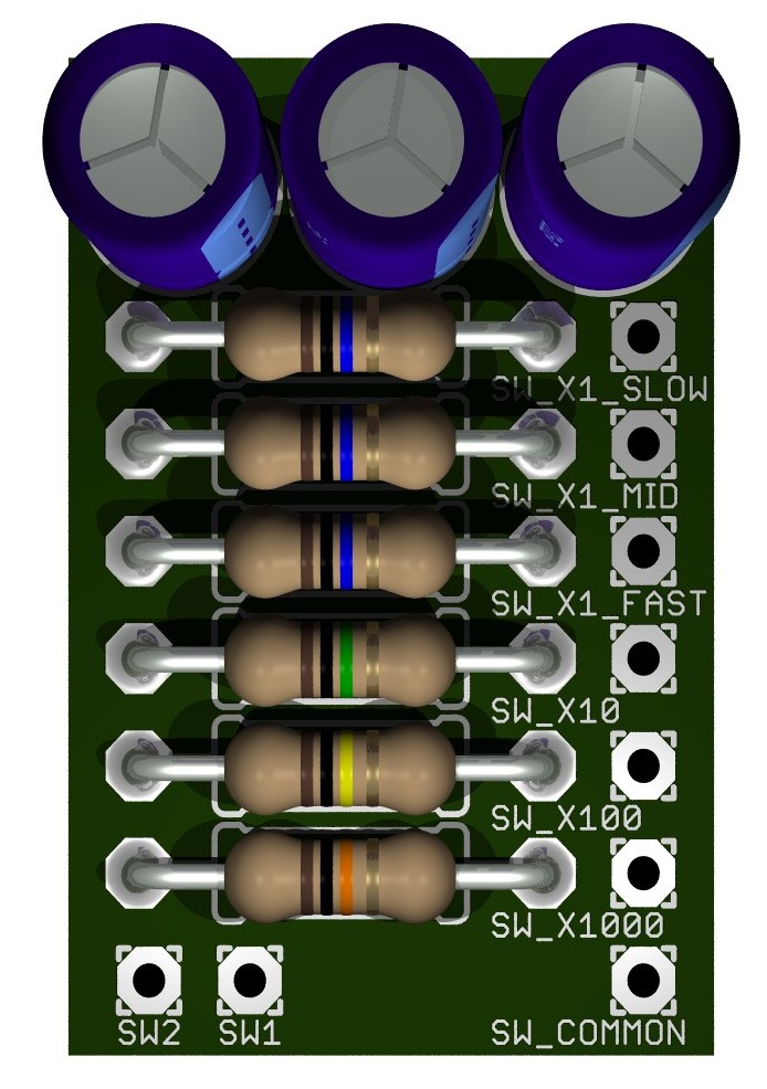
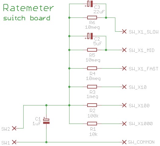
RC networks (on the PCB of the flow switch) provide a simple method, very accurate and straightforward to get several courses with a single integration capacitor. With this method the integration time automatically adapts to the different levels of radioactivity. The low range provides a choice of three integration times to increase the accuracy of the measurements at the expense of responsiveness.
A six position switch provides precise and linear scale that do not require calibration.
Capacity x 1000 (from 0 to 100 000 CPM with integration of 30 mS)
Magnitude x 100 (from 0 to 10 000 CPM with integration of 300 mS)
Range x 10 (from 0 to 1000 CPM with integration of 3 seconds)
Range x 1 (from 0 to 100 CPM with integration of 30 seconds)
Range x 1 (from 0 to 100 CPM with integration of  3 minutes)
Range x 1 (from 0 to 100 CPM with integration of 15 minutes)
This compressed file contains the projects Eagle for the ratemeter and switch PCB, electrical simulation to ASC format to LTSpice, 3D images, schematic and Gcode for milling PCBs:
Ratemeter_EagleProject_Images_And_Simulations
A Checker and a Ratemeter, created by Alessio
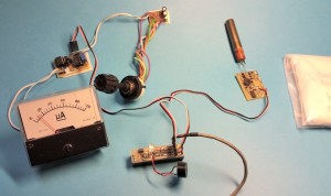
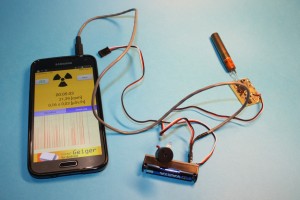
Click on images to enlarge them.
In the left picture you see the complete system: Checker + Ratemeter + Geiger Adapter + Geiger Tube + dietary salt bag containing Potassium.
In the right image you can see the lonely checker, connected to a smartphone, with Geiger application (free for Android)
In this YouTube video you see all in function: http://youtu.be/lwtVInDgFwY
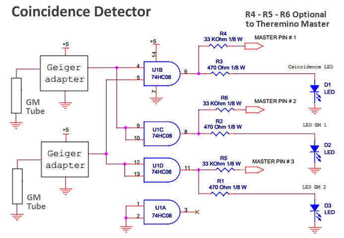
Coincidence detector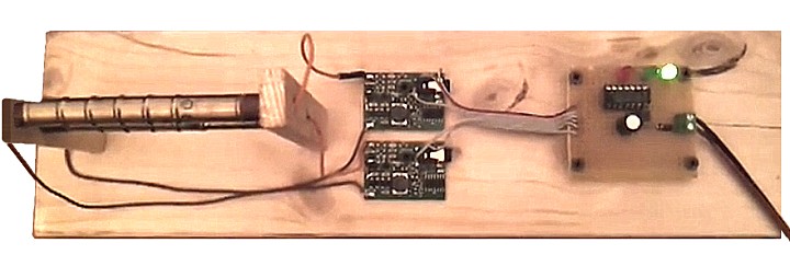
This is the detector of coincidences of Alessio, You can see it work in this video:
http://www.youtube.com/watch?v=820ifYlyc0o
Documentation and notes for using the coincidence detector:
CosmicRaysDetector_ITA.pdf
CosmicRaysDetector_ENG.pdf
Other information on the detectors in coincidence, cosmic rays and muons, here:
http://hardhack.org.au/book/export/html/2
The scheme is simple and can be assembled in five minutes even on a Breadboard. If you connect the outputs to a Master you can count regardless of the three channels by configuring the input Pin as simple Counter. You do not need to set the pins like FastCounter, because the number of events per minute is very low.
Click on the image for a larger view.
If the two GM tubes (Geiger Muller) emit a pulse at the same time the door U1B reveals this coincidence with a pulse output that the Red led.
Contemporary impulses may be randomly generated by two contemporary disintegrations, but the probability of this happening is very low. About one chance in a hundred thousand (Since the pulses of the tubes are about 100 us and that occur a few pulses per minute).
Then, If the Red led lights, We can say with 99.999% of probability, It was revealed a cosmic ray.
Super accurate coincidence detector
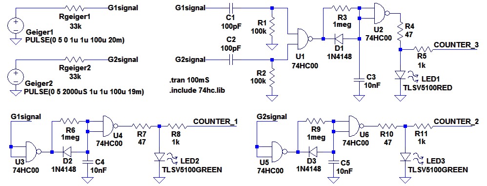
All realizations of coincidence detector worked well but has anyone asked to have the brightest LEDs. So here's an improved version. This version also has an input circuit tightening impulses from normal 100 – 150 us about 6 uS, bringing the probability from 99.999% to 99.99995%
Yes, It's true, This is an exaggerated pignolaggine and practically no one can see the difference. Who doesn't want this benefit can eliminate C1, C2, R1 and R2.
Improvements:
- The LEDs are switched on for many milliseconds and so are fifty times brighter than before.
- The input signals are tightened a few uS whereby the random coincidences are reduced virtually to zero.
Here is the new schema:
Note that we kept the output resistors R5, R8 and R11 are very low, in order to use shielded cables of more than one hundred meters (someone does it). Therefore the LEDs must be present, Why limit the voltage sent to the pins of the system Theremino.
And this is the simulation files: CoincidenceDetectorV4
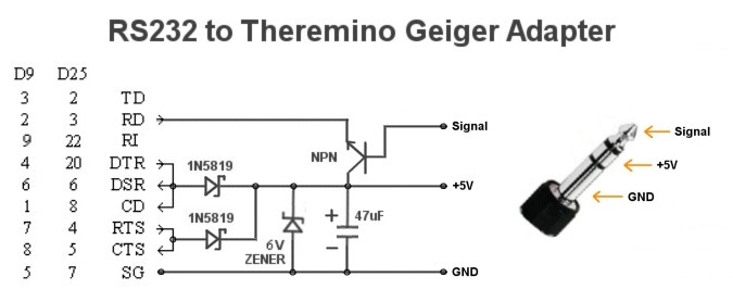
An adapter between the GeigerAdapter and the RS232 port
This adapter allows you to connect your GeigerAdapter directly to your PC, without using a ThereminoMaster. Power is drawn directly from the serial port DTR and RTS signals. The pulses are reinforced with a transistor (any small NPN is suitable) and sent to beacon RD, It interprets them as start bit. Whereby at each pulse you will receive a character (the value of which does not matter).
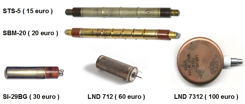
Geiger Geiger for use with Adapters
These are the recommended geiger tubes, are the best and we tried them long. Prices in parentheses are only indicative, This is the price you found on eBay.
Radiation sensors with PIN diodes
PREMISE
Unfortunately the evidence about the Pin diodes are not progressing well. Also in theory, putting many in parallel sensitivity is always poor. A tube SBM20 works best, does not require charging amps and delicate also sees the beta rays, and very low energy.
Spice simulations gave good chances in this project and hoped to be able to make cheap spectrometry. But trying the charge amplifier, with 10 diodes BPW34 and with a strong source of Gamma Rays (thorium mantle), the results were disappointing. Told with words similar to those of Einstein: “We have combined the theory to practice and did not work a tube”.
Or is there an error of concept (very narrow bandwidth for example) or we missed some serious experimental error.
For those who want to repeat the experiments, Here are the Spice and Eagle projects, how far we came: https://www.theremino.com/uploads/Sensor_ChargeAmp_V1.zip
The wiring diagrams are available as images and Eagle. Spice files are for “Circuitmaker”, the old Simulator that we used before LTSpice. Not having CircuitMaker, You should redo it to LTSpice.
And attention: you have to shield everything from light and electric fields, while letting Gamma Rays. And you have to build a small PCB, exactly as directed by us, otherwise the parasitic capacitance, combined with the large amplification will auto-swing.
Pin diode radiation sensors are cheaper, But even less sensitive, a Geiger tube. One of the best Pin diodes to use is BPW34, It costs about 0.5 Euro. The sensitivity of the BPW34 is about 0.6 CPS for mR/hr (about one twentieth of a geiger tube). To amplify the weak signal of pin diodes you need a charge amplifier, but those available on the market are very expensive (from 150 to 300 euro and more), they have a fairly high power consumption and require a dual power supply (usually 12 volts positive and 12 Volt negatives).
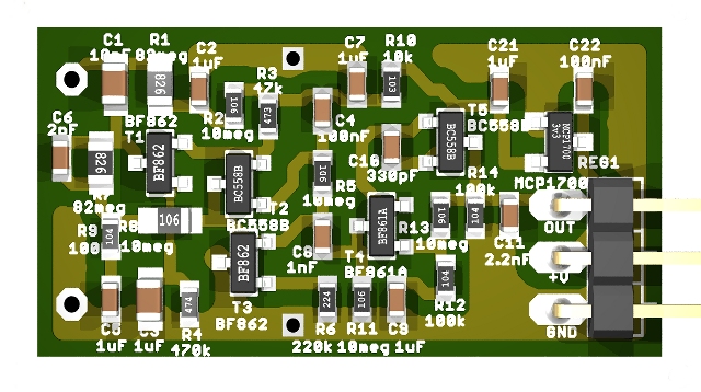
This charge amplifier at low cost, developed tailored to the system Theremino, It has a very low power consumption (about 10 micro amps) and can be powered with a single voltage 3.5 to 6 volts. Its good noise characteristics allow to amplify many pin diodes in parallel increasing proportionately the sensitivity.

