
——
New version 7 – Year 2021
This version contains all the experience accumulated in almost ten years of experiments.
In this chapter you will find all the necessary documentation, consult previous versions only if you are interested in the history of this project.
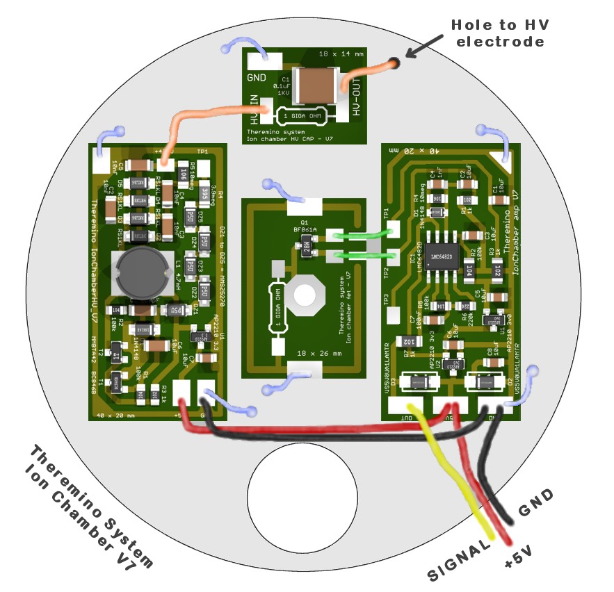
Construction is greatly simplified, all the electronics are located on the same side of the chamber (without the shielded cables we used to go to the amplifier on the opposite end).
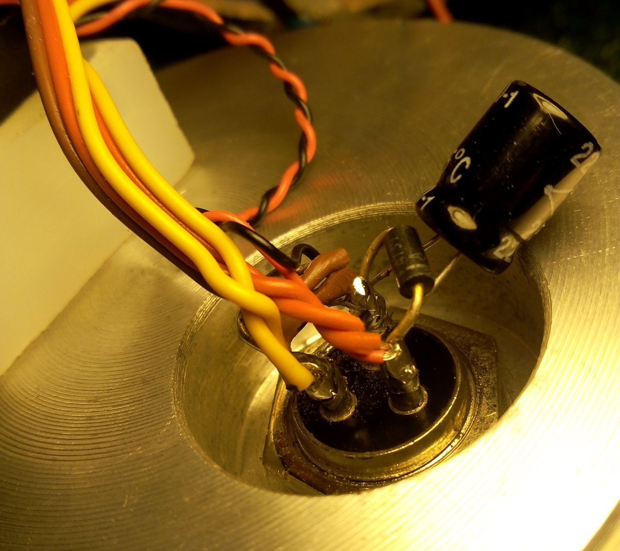
PCB modules have become so small and light that you can secure them with rigid tinned copper wires (blues in this image), welded to the tin plate surface (or on the surface coated with copper tape in the professional versions of the chamber).
In addition (but we will see it better later), covering the FET with a rectangular screen and the hole with a fine brass mesh, it is possible to make the open chamber work, with fully accessible electronics, as seen in this image. And this is a great convenience when measuring components before closing the chamber.
The improvements are substantial!
- Great stability of the parameters, even with strong temperature variations.
- Significantly improved measurement accuracy.
- Less background noise and less sensitivity to disturbances.
- Ease of construction.
- Simplified wiring of connections.
- Easy replacement of modules.
- Possibility of making measurements on components even with the chamber open.
DOWNLOADS – V7
All documentation in PDF format:
Radon_IonChamberV7_Construction_ENG.pdf
Radon_IonChamberV7_Electronics_ENG.pdf
IonChamberV7 / Radon_IonChamber_ENG.pdf
IonChamberV7/Radon_Info_ENG.pdf
Radon_IonChamberV7_Construction_ITA.pdf
Radon_IonChamberV7_Electronics_ITA.pdf
IonChamberV7 / Radon_IonChamber_ITA.pdf
IonChamberV7/Radon_Info_ITA.pdf
Radon_IonChamberV7_Construction_DEU.pdf
Radon_IonChamberV7_Electronics_DEU.pdf
IonChamberV7/Radon_IonChamber_DEU.pdf
IonChamberV7/Radon_Info_DEU.pdf Thanks to Heiner Gerling for the German translations.
Radon_IonChamberV7_Construction_FR.pdf
Radon_IonChamberV7_Electronics_FR.pdf
IonChamberV7/Radon_IonChamber_FR.pdf We thank Jacques PAGES for the French translations.
IonChamberV7 / Radon_IonChamber_ESP.pdf
All original files in ODT format (OpenOffice), for translators:
https://www.theremino.com/files/IonChamberV7/IonChamberV7_OdtDocs.zip
The schemes, the most recent PCBs and simulations:
HTTPS://www.theremino.com/files/IonChamberV7.zip
– – –
The components are all readily available and inexpensive,
the only doubt could be given by the resistors from 1 Giga,
you can find them at a good price following this link.
The Theremino Geiger application can be downloaded from This page.
Information about previous versions and some old images in This page.
If you can't find the components or build the printed circuit boards
ask them to Lello ( maxtheremino on eBay )
or write to him at: ufficiotecnico@spray3D.it
– – –
You now have everything you need.
This is where the previous versions begin,
consult them only if you are interested in the history of this project.
——
Premises for the version 6 – Year 2016

In recent months research into the ioni Chamber for Radon have led to unexpected results and new discoveries. Part of these discoveries are credit for experimenters, around the world, the most active is definitely Pavel Provaz, He has already experienced a great number of different configurations (and invented the new single wall version). On this page we list the results of the most recent comments.
Many people have experienced that the room, After running a long ago, suddenly loses sensitivity and, After some time, starts working fine. And have questioned whether it can depend on high-voltage variations, or other parameters.
ANSWERS
I HV nothing to do, may vary from 450 to 550 Volts without causing differences in measurements.
And even tension on the TP1 is insignificant, depends very much on the FET. Some FETS have a current (with Gate open) highest and then the TP1 salt a little. But the tension on the TP1 salt also, and very, in the presence of moist air. And under these conditions the FET amplifies less.
So these flaws are almost certainly caused by air humidity.
In recent months we have discovered that the air over the 70% RH can lead tens of pico Amps (and up to over 500 PA when you get close to 90%). We are therefore studying a room that can work even in very humid environments (Besides, no rust)
The first solution was to dehumidify the air (that you send to the Chamber through a pipe and a small fan). The dehumidifier consists of a serpentine carved on one side of a piece of aluminum from 5 x 5 cm and up 10 mm, with a Peltier cell that cools it. The coil is facing down and a cloth collects water drops and evaporates.
But the dehumidifier is not a very elegant solution and consumes a lot of power. For which we are studying some solutions for moisture and some improvements, for other aspects:
- First of all a central electrode in 2 mm brass tube (that greatly improves resistance to mechanical noise)
- An external wall made of stainless steel or aluminum.
- New pattern of polarization of the FET Gate FET grounded through resistor from 1 Gig Ohm bearing hundreds of air leakage current picoAmpere.
- New circuit amplifier (version 6).
- Attempts to eliminate the double wall, loading the Central pad with 500 Volts (about) and isolating the Gate with capacitor 1000pF.
A cool new idea is to protect the ions from moisture by closing in a polyethylene bag. Polyethylene stops is the water vapor that Thoron, but lets move on Radon. The polythene bag acts as a polymer membrane (radon has first to dissolve and then spread) It must be very thin to not impairing the response.
Those wishing to do experiments, may write to Alexis, who knows where to find the components and can prepare new PCB.
New amplifier – Version 6 – Year 2016
From here you can download the pattern, the PCB and the latest simulations:
https://www.theremino.com/files/IonChamberAmpV6.zip
And here you can buy cheap resistors 1 Giga:
http://www.mouser.it/ProductDetail/TE-Connectivity/RGP0207CHK1G0/?qs=%2fha2pyFaduhkrdcbzNk6CHQ1bfgoVndRtlEgfJiN2nuM8RBuTFoG3A%3d%3d
Sure that the resistor must be COMPLETELY INSIDE the inner Chamber, otherwise collects complaints and does not work anymore.
Note that if you polarize to mass the Gate tension on TP1 becomes about 0.3 Volts and will no longer be modified by moist air (before the normal voltage of TP1 had 1.1 to 1.3 Volts and saliva very, even beyond 1.5 Volts, in the presence of moisture. And when the voltage on the TP1 salt, the FET amplifies less, and there is a strong loss of sensitivity to low amplitude pulses. Why there are fewer impulses.
The latest versions also include a regulator LM385 which further reduces (In addition 30 times) the noise coming from USB. This improves the functioning on some particularly noisy PC.
The most recent research has shown that a strong air humidity, as well as conducting a stream of hundreds of picoAmpere, It also causes rapid variations of current. These changes result in a loud noise on top of the impulses (visible on TP3 with an oscilloscope). Everything is amplified by the presence of dust in the air (the powder gets wet and increases noise)
We don't know so until humidity level you can get, but we're pretty sure that, beyond the 90% of moisture, the disturbances become that breadth, that no room at ions, However that may be built, might work.
New high voltage power supply – Version 5 – Year 2015
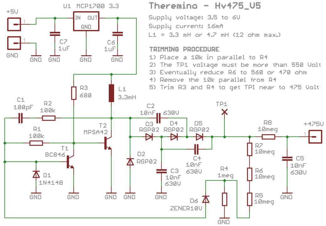
 Schematic and PCB power supply dell ’ version 5, with traditional components.
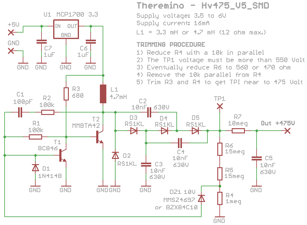
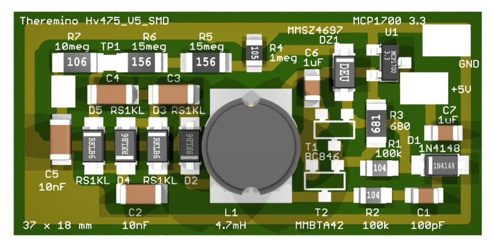
Schematic and PCB power supply dell ’ version 5, with surface mount components.
Adding a remote controller 3.3 High voltage ’ Volt will prevent l from being disturbed by noise from the USB. The baseline which is measured on the TP3 is more stable and more precise measures are then. On some PC with USB voltage very noisy this new power supply can make big difference.
With this link you can download the pattern, the PCB and simulations, both the ’ amplifier power supplies, in both SMD with classic components: IonChamberCircuits
Significant improvement in stability
In the last year (2017-2018), Some rooms have given ion problems. Suddenly began to generate an exaggerated number of pulses. In other cases the impulses they didn't seem caused by an effective Radon concentrations. These episodes appeared correlated with temperature changes.
Electrical tests showed no abnormality, so for a long time we have blamed mechanical causes and dust particles. Unfortunately the rooms that were flaws stopped them just changing something. It was enough to open them, move the wires and connect them to the oscilloscope and magically they correct alone.
At last (15 July 2018), one room has started “do the fool” while the oscilloscope was connected. And fortunately the signal on TP3 showed an anomaly. A swing at very low frequencies.
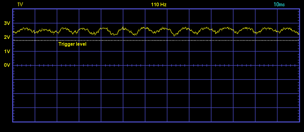
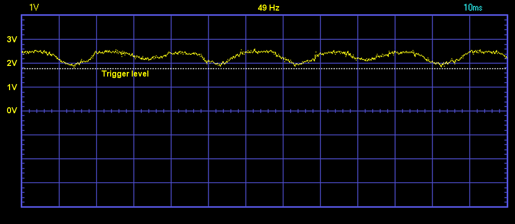
The frequency of this oscillation changed continuously, If saliva its amplitude decreased, If he descended the amplitude increased. Going down under 50 Hz amplitude increased until the shooting line, and so was likely to trigger false counts, as seen in the next picture.
Further tests have shown a high frequency autooscillazione, the output of the integrated high voltage stabilizer U1 feeder. And an oscillation frequency dependent minor variations of the external capacity (move threads or open or lids), or temperature fluctuations.
At times the frequency of autooscillazione, approaching to the oscillation frequency of the transistor T2 (both about 10 KHz), generates a low frequency beat (sotto i 100 Hz).
The very low frequencies, not being sorted effectively by capacitors C3, C4 and C5, caused a continuous swing of tension on the verge TP3. This product could reach even higher voltages than a volt and began to produce spurious pulses.
Once you understand the problem the cure was simple. Delete the autooscillazione increasing the two capacitors (C6 and C7) up to 10 uF. The datasheet of the MCP1700 regulator recommends the value of 10 UF to avoid self oscillate, but this information was unfortunately little evident and is “escape”.
To further enhance stability, It also adds a capacitor by 220 uF (electrolytic from at least 10 volts) connector that brings 5 input volts to the room.
The image below shows that with these changes the voltage at the TP3 is stable, no more traces of ripple. The signal is consistently well away from the operating point (almost one volt), so the risk of abnormal impulses is completely eliminated.
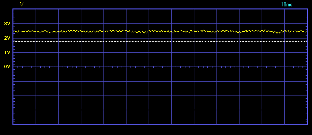
In this picture you see even a slight undulation, that was caused by too close to the center electrode fan. Removing the fan than two centimeters this noise is eliminated. In the next image we can be seen that the only remaining noise is random noise caused by the ionization of the air.

In the two images below you can see an enlargement of the disturbance caused by the fan.
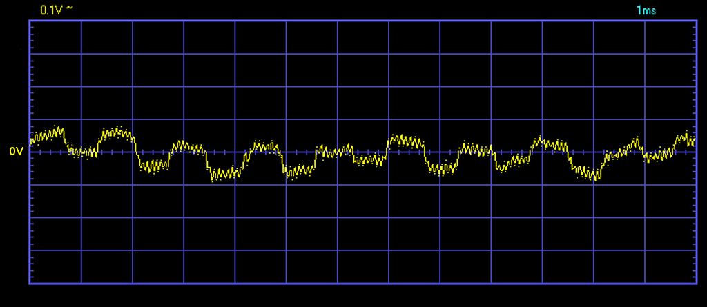
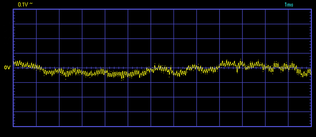
In the first picture, the fan was positioned close to the inner Chamber, the second was dismissed by 20 mm.
The disturbance caused by the fan is recognizable because it is a square wave with a frequency of approximately 500..1000 Hz. Instead, the high frequency ripple (about 10 KHz) It is the residue of the high voltage supply commutations.
These residual noise (even that caused by the fan), they really are minimal and cannot create problems. But it's good to know they recognize and control not exceeding 100 MV peak to peak.
Fixes compared to previous projects
Now the tension on the TP3 is more stable than it has ever been, that would be good to correct all rooms built above, with two ceramic capacitors 10 UF and electrolytic 220 uF.
Also last year, a room was damaged by lightning (He had a long connection cable between the Master and the room). So to avoid this risk, It would be good to add two zener diodes, one between GND and + 5V, and the other between GND and the signal. These zener must be from approximately 6 or 7 volts (for example, 1N4735 or 1N4736), and must have the anode (the side without clamp) connected to GND. It would be good to add the zener on both connectors, two on the ion Chamber connector, and two out of the box that contains the Master.
And finally, to mitigate transient disturbances caused by the ignition of heavy loads, you could add a ceramic disc capacitor 100 nF, on the connector, right at the entrance of the room.
How to make corrections
In the next image you can see the components soldered directly onto the connector.


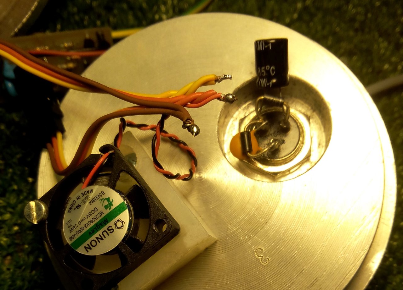
This is a robust and efficient example (They delete own entrance disorders). But it takes skill with a soldering iron. So in some cases it might be better to adopt different provisions, or even a piece of PCB or veroboard.
“Concentration” or “Activity”, That's the problem!
Until a few months ago, we measured the “Radon concentrations”, whereas now we measure in “Radon Activity”. We had to adapt to this custom to give similar values to other Radon measurement devices on the market.
To calibrate the ions in “Radon Concentration” the value to set is 2.15 CPS/Bq/l. With this adjustment the values in Bq/l and Curie/l will be about five times lower.
To calibrate the ions in “Radon Activity” the value to set is 0.43 CPS/Bq/l. With this adjustment the values in Bq/l and Curie/l will be similar to those measured with other devices on the market.
In European Commission report There are excellent definitions of two units of measure.
- "With “measurement of concentrations of radon” refers to the number of disintegrations of the isotope Rn-222.
- The term "exposure to radon" means the exposure to radon progeny. "
Given that we convinced ourselves, If everyone uses the activity will we. We want to point out, however, that “should” measure the “Radon concentrations” and give values about five times lower, come suggerito da tutte le organizzazioni internazionali.
Documentazione che suggerisce di usare la “Concentrazione”
Sia “Word Health Organization” che la “European Union” suggeriscono di usare la “Radon concentrations”
https://www.uic.edu/sph/glakes/radon_measurement/pdfs/unit_three.pdf
http://www.atsdr.cdc.gov/PHS/PHS.asp?id=405&tid=71
The World Health Organization has recommended a radon reference concentration of 100 Bq/m3 (2.7 pCi/L).[82] The European Union recommends that action should be taken starting from concentrations of 400 Bq/m3 (11 pCi/L) for older dwellings and 200 Bq/m3 (5 pCi/L) for newer ones.[83]
http://en.wikipedia.org/wiki/Health_effects_of_radon#Radon_concentration_guidelines
Radon concentrations in the air are measured as the amount of radioactivity (Bq) in a cubic metre of air: http://www.who.int/ionizing_radiation/env/Radon_Info_sheet.pdf
The concentrazione di radon si misura in Becquerel per metro cubo (Bq/m3 ). Il valore di 400 Bq/m3 indica la disintegrazione di 400 nuclei atomici di radon al secondo in un metro cubo d’aria accompagnata dalla emissione di radiazioni ionizzanti.
Radon concentration stairs
http://en.wikipedia.org/wiki/Radon#Concentration_scale
But then why all manufacturers of similar devices use the “Radon activities”?
Probably because this causes you exceed the limits of the law and it becomes easier to propose costly remediation. This is only a supposition, but until someone suggests a better explanation…
An ion Chamber “embedded”
Alessio has developed an ion Chamber with all software in a PIC Microcontroller. This solution is especially economical because it does not require a PC (or tablet).

With one button you maneuver all functions. The display shows the version, currently “Radon Detector Ver. 1.0”, the seconds elapsed and the concentration of Radon gas in Bequerel per cubic meter.
William wrote:
I have experienced a loss of sensation around four times, in conditions of dry air (about 50% in recent days). It could be caused by “oxidation” Central electrode? And then from a minor family of strokes, produced by disintegrations, from the air to copper?
Answers:
As far as the oxidation of the electrodes decreases the conduction, does not affect the amplitude of the pulses, the reasons are as follows:
1) The pulse current is so small that even a very high resistance (thick oxide) does not decrease the amplitude in measurable ways.
2) As far as the electrodes oxidize, There is always some space between the oxidized points (microscopic perforations of the oxide) and these perforations, combined with the slight conductive layer that forms on all surfaces for effect of moisture, lead to still have a surface in electrical contact with the metal. Maybe it's contacts with high resistance, perhaps hundreds of mega ohm, but the only effect of this resistance will only slow the ascent of impulses. In the end, however, all offices will arrive where they arrive and you will not notice any decrease in amplitude of the pulses.
3) We tested this by coating the Central pad with a sheet of paper. The paper "should" be an insulator but actually has a strength of tens of giga-ohm. And the result was to have exactly the same impulses of an electrode does not "block" with paper.
Loss of sensation
———————————————————————————–
Since you didn't have a strong moisture then we don't tell you what could have happened. We suggest anyway to inspect the TP1. If there are leaks (due to moisture or other) the tension on the TP1 salt and when it gets to 1.5 Volts and over the sensitivity decreases a lot and there are few pulses.
Burst pulses
———————————————————————————–
If you count pulses per burst check TP3 with oscilloscope. If it's 50 Hz then you must improve the shielding (brass double holes netting). If they are, then this may be caused by conducting random undulations moist air.
I wanted to update the situation with regard to the above comment posted in my name by Livy.
After a review of the room made by him, with replacement of any faulty component, the sensitivity and stability of the room has reached very high levels.
I implemented, taking advantage of the free channels, pressure sensors, temperature and humidity (Thanks to the good Alessio!!), in order to have a complete picture of changes in the conditions of measurement (any air movements that occurred during the measurement) that may change the data.
I leave you with a chart “cool cool” made of very low concentration condition (environment with controlled mechanical ventilation).
https://drive.google.com/file/d/0ByNPlNE2fCMqT1ZZeDZwTENxMkE/view?usp=sharing
The realization of ionic room I am not clear what potential is connected the armor of the jar with lids.
If it's a shielding, should I connect to “ground-earth” (ground/reference) or is it better to leave it floating ?
I do not find this information on the designs and I would appreciate it if you could clarify this point.
Thank you to all the team and congratulations on your excellent work.
Should be connected to GND.
The best spot is the negative of the connector where the three wires from the Master.
If you leave the flying outside disturbances, coming from the electrical system, saturate the preamp and does not work anymore.
On this page there are a lot of useful information:
https://www.theremino.com/hardware/inputs/radioactivity-sensors
Thanks Livio for your answer.
I would have a few more questions : How can you be sure that the measurements obtained with Ionic radiation actually depend on Radon Chamber ?
If you are using a geiger, instead of the ion Chamber, It is possible that the count is in part due to the presence of Radon ?
To conclude: isn't it true that alpha/beta and gamma radiation are all detectable using the concept of ionization ?
Thanks for your great patience, Mario
Beta and gamma ionize them too, but the number of molecules are ionized by any disintegration is about a hundred times less than those produced by Alpha disintegration.
Also the disintegrations of Radon (and also of Thoron) have energy from 5 AI 7 Mega electron volts, versus just a few hundred KeV beta and gamma of products from almost all radioactive substances.
Whereby the electrical impulses that develop after the FET are decently sized for Radon and Thoron but so small as to be absolutely not measurable for everything else.
In any case a room count-ion as our beta and gamma does not see them just. To be sure we used very energetic samples of various substances and we never saw pulses produced by none other than radon.
Radon decays and his sons are only alpha and Beta. These Betas are weak, only a few hundred KeV and (as far as detectable by a geiger) merge with the natural background not be measurable.
Finally, geiger tubes have a sensitive volume small, Perhaps a thousand times less than a litre of our room at ions. So in an environment where we measure a disintegration of radon per minute, a gaiger would span one disintegration per thousand minutes (sixteen hours) and this count would be totally masked by the counts due to the environmental fund, a hundred times more frequent.
Thanks again Livio and congratulations for your project. Group of enthusiasts.
Personally I am extremely intrigued by the phenomenon of Radon and the radioactivity in General.
Unfortunately I find that the realization of the ionization chamber and electronic forms is very laborious and provides a result of hobby flavor, but I think I'm now in final phase.
Mario
Of hobby there is only the cost of materials. When was compared with professional equipment (We do not make names for correctness) was found to be superior in everything. Mainly faster but especially usable comfortably. By connecting it to Geiger, you get a chart already significant in record time (half an hour), While other rooms “Professional” still chew into them and then, After many hours, a single number.
The chamber outer wall needs to be connected directly to amplifier ground pin, or connected to ground with minimum 100uF capacitor. OR you have to connect the minus of the amplifier to some external ground by wire. So 3 setups are possible and working. Otherwise you will experience very high noise.
In fact, there needs not to be any shileding of the chamber, you can use only a single wall can. I have tested that and I’m still using it in one of my devices. But in that case (if there is not GND on the chamber wall, but positive or negative high voltage), you have to increase the output HV capacitor to 100uF, otherwise the noise will be very high (it acts in this case also as a high pass filter, connecting the chamber wall noise to ground. With this capacitor value the additional induced noise is reduced to not detectable and a single non grounded can can be used, but it is very dangerous and also the startup time is longer… I would recommend that only in case you are encorporating the radon meter into some insulated housing box. Also a 100uF cap for that high voltage is quite expensive. On the other side it is much easier to DYI.
As mentioned above, I have also tested a configuration with a single grounded can wall and central electrode injected with high voltage. It works well and it is obviously much safer. But the S/N Ratio achievable with this setup is little lower (less than 70%) and also a performance in high humidities is little worse. And, of course, because in this case the chamber is of one potential, a higher calibration factor must be determined, because the whole chamber surface is active (There is no loss of ion stream at both chamber ends, as in original version).
Heh, my name was translated automatically from Provaz to “Rope”, when entering the answer :-)
We do not use a 1 uF capacitor bur only about 33 nF that is not dangerous. Then to reduce the noise we use a 10 to 100 Mega ohm resistor and a HiVoltage generator with a double stabilized power supply.
But your solution with the central electrode charged with high voltage can work very well. Now we have no time, but sooner or later we will test this configuration and publish a modified version. Thanks for your tips.
It is possible, that this 10 to 100 Mega resistor will affect performance in high humidity environment (over 80%). It may cause lowering of the high voltage and thus a loss of sensivity. But it is safer, that is absolutely true.
Livio, I run the first tests of the ion Chamber, However, while measuring the high voltage (up TP) about 500VDC and the amplifier with the correct biases, I can't get the impulses even after 30′ of waiting. I set what had seemed more correct (Ion Chamber sensor, etc) in the program, using HAL: PIN1 – Slot1 – counter mode on the master.
The master flashes quickly, but I can't seem to get ever pulses. And’ possible to have a sample setup for the program IonChamber.exe be used for Radon ? Thank you.
PS: given that the forms of the Ion Chamber (HV and AMP) are made with SMD components and thus are “high”, You cannot close the cover as indicated in the project. I had to add another cover as thickness, soldered to the other two, to create a gap. If there are cracks you must tap them with The adhesive tape or can remain without problems ?
Thanks again, Mario
Hello,
If there are cracks, or not put properly grounded all screens, does not work anymore.
If there are long strands in this case does not work.
The room is delicate and should be mounted without “variations” compared to the draft.
If you set the output Slot in geiger other than in hal then not working (try to knock them over, If the slots are in place should count)
The hal you should set Counter and not CounterPU.
If it doesn't work you can send her to Alessio will place.
It would be interesting to see how you got to use 2.15 CPS/Bq/l. as calibration factor.
You can ask more precisely to Marco Catalano di Lacerc (OnLine certifications):
https://www.theremino.com/contacts/about-us#marco
For now I answer what I remember…
1) The calibration factor was modified to adapt to gauges that matter even the disintegrations of the descendants of Radon. It wouldn't be fair but they are all so.
2) The current factor is then 0.43 CPS/Bq/l.
3) To get to this given Mark has prepared a special unit with pipes, fans and a source of Radon. Then it went to a laboratory to compare it with other secure meters. Can't remember the name but I think it was a laboratory of Arpa.
If you need anything else just ask or email us at engineering@theremino.com
Livio, I made Theremino with the Ion Chamber for Radon, afterwards, being a big fan of electronics, I thought I'd connect the Ion Chamber to a coupon with LCD that I designed to count the CPM of the sensor. The microprocessor is a PIC16F876 that I programmed with MPLAB-X in XC8. The prototype works well and each pulse on a LED launches a disintegration and send a clicks per piezo buzzer.
Now I would like to see not only the value CPM, but also the equivalent dose in uSv/h. Then I'll use even with a Geiger (SBM-20) already note the conversion constant.
But for the Ionic room how do I convert CPM in uSv/h ? Thanks and good job. Mario
The empirical formula can be obtained from ThereminoGeiger, But even more easily I advise you to predict a number K.
And thou shalt: USV/h = CPM * K
At the beginning set K = 1.000 and then the change by comparison with Geiger until similar readings.
However without Geiger which averages over time and figure you'll get raw data and not very significant. It would be much better to use a Tablet with 8 inches by 49 Euro Windows 10 and Geiger. You would provide the power, the battery charger l lithium and CE approved, the touch screen, the sounds of clicks, the Wifi if you want to see it from a distance… Or, even better a Meegopad from 80 euros which is very small and only consumes 200 but to 5 Volts.
All controllable from a distance with TeamViewer via Wifi and also via the Internet.
Hello,
I made Ion Chanmber for radon according to your circuit diagram and it functioned very well.
However, the noise caused by the weak breeze and vibration is also counted.
Is there any ways to reduce the noise?
Hi, Dominic
the only method to reduce noise is a more rigid mechanical construction.
– The central electrode should become a small brass tube (of those used to obtain fuel in model aircraft).
– The outer cylinder should be a thick, heavy aluminum cylinder.
One of our collaborators “Marco” builds professional ion chambers with this method
and they are considerably less sensitive to vibrations.
https://www.theremino.com/en/contacts/about-us#marco
Here you can see the professional version:
https://www.theremino.com/blog/geigers-and-ionchambers/ionchamber-improvements
Last professional version are simplified,
the number of internal components is reduced
and it is more easy to open end close them.
https://www.theremino.com/en/hardware/inputs/radioactivity-sensors
Hi there….
Could the Texas LMP7721 be a candidate for further development. It seems that is is designed for also ion chambers, and with a low bias current of 3fA? Maybe to elliminate the BF861?
http://www.ti.com/product/LMP7721
Best regards Murdock.
No, it will self-oscillate.
The FET must be physically inside the chamber, so the GATE remains fully shielded.
The FET GATE does not have to “see” the other parts of the circuit, otherwise the microscopic capacities that are formed through the air, would collect the output signals of the first amplifier stage, and also the strong square wave signals of the final output.
These signals are millions of times larger than what we have to measure. So they would cause strong input noises, that will be amplified and cause a self-oscillation of the whole circuit.
Hi.
I have built a ion chamber ( Tomato can ) approx 52mm x 65mm (140ml) driven with 250Vdc. It works great with almost no noise on the baseline. But how do i find the best suited voltage for a smaler chamber. Do you have some doc whit regard to this issue?
Best Regards
Murdock.
The best voltage is about 100 volts every 10 mm of radius.
Increasing this tension has a small increase in sensitivity, but a greater instability and noise produced by the humidity of the air.
Hi again.
I’m having trouble figuring out if the chamber shell it self is floation or grounded?
Best rgd John Hansen
Have just found the answer in earlyer reply ……
Ok thanks.
Hi Livio.
Is it possible read out the absolutely max. puls amplitude for the (PO214- 7,4 mev) and min. (po210-5,3 mev) and the back calculate the threshold level to detect only randon and discriminate beta’s?
Lets say that po214 is 100% puls and po210 is around 65%, then the threshold is set to lets say 60%????
Why do i ask, because i have changed the gain on the amplifier so i wont get flat/chopped pulses that goes below “0V”. I also have a sleight different size of the chamber.
Best Regards J
ENGLISH
Not only the energies count but also the ionizing power. Alpha rays have an ionizing power hundreds of times greater than gamma rays, and a thousand times greater than beta ones. Therefore, beta and gamma rays do not produce measurable electrical impulses in a counting ion chamber like ours.
The threshold does not serve to exclude beta and gamma but to reduce sensitivity to mechanical disturbances. Raising the threshold reduces the number of counted pulses somewhat, because it excludes the weakest impulses. The weak impulses are not weak due to a different energy, but because the disintegration occurred near the metal wall or in the terminal areas of the chamber where the electric field is smaller.
ITALIANO
Do not count only the energy but also the power ionizing. Alpha rays have an ionizing power hundreds of times greater than the gamma rays and a thousand times more than beta. So the beta and gamma rays do not produce measurable electrical impulses in an ion chamber like ours.
The threshold does not need to exclude beta and gamma but to reduce the sensitivity to mechanical disturbances. Raising the threshold reduces bit’ the number of pulses counted, because it excludes the weaker impulses. The weak pulses are not weak due to a different energy, but because the disintegration occurred near the metal wall of the room or in the end zones where the electric field is less.
Dear Livio
I’m building now the Radon Chamber.
I have the chamber with dimensions outer fi=80 mm, sheld chamber fi=90 mm, central electrode as rod fi=2.7 mm, all parts from SS. Distance between two cylinders is made from two epoxide laminate rings (no polymer film).
At this moment I have two options: as your project and my proposal – negative tension connected to shelding chamber (on GND potential), the chamber with fi=80 mm connected to gate of FET’s (the gate of FET’s connected to GND with 1 GigaOhms resistor) and the positive tension of 480 V connected to central rod. And your oppinion is???
Additional, in your project, the picture “DSCN4252,JPG” from the chamber doccumentation (V6) is unclear. I can find 10×82 MegaOhms resistor, the vertical pipe is probably central (?) electrode with connector to the FET’s gate. But the copper ring is for????? And method of mounting in the chamber???
I answer in Italian because it is easier, please translate with Google or by consulting the website translated pages.
We never tried to connect the gate of the FET to the outer cylinder and the positive center post, so I can not tell how it might work. But I see a problem caused by the large electric capacity which would create, between the cylinder (then GATE) and the outer shield. Most likely this ability will alleviate the pulses so as to make it impossible to distinguish from noise.
In the image you speak of the resistors 82 mega are only one of many ways to connect the gate to GND with approximately 1 gig ohm. You could instead use a single axial resistor 1 giga, located Mouser or other retailers.
The vertical tube is the central electrode and the connector serves to connect the FET.
The copper adhesive ring served as a base for a weld shielding, in tests with open chamber (keep in mind that everything has to be very well shielded, otherwise Capti the electrical grid and you do not see the pulses).
This was just an example to show how to build a resistor 1 jig with resistors 82 Mega, that cost a few cents. The mechanical construction can make it in many ways. You do not take this as an example.
Hello Livio
Thank you very much for your reply. It is very helpfull for me.
At this moment I don’t connect the ampliefier to chamber and after your reply I will connect the HV and JFET’s gate in “classical” way.
For your information, I have measured capacity between the cylinder (then GATE) and the outer shield. I have obtained the value of about 110 pF, because the distance between is 5 mm. In future, if I will find time, I probably will test the reverse connection.
With best wishes for you
Andrew
The 110 pF is about 20 times the normal Gate + electrode capacity
(normally we consider it about 4 pF)
Adding 110 pF in the LTSpice simulation, the pulses on TP3 are reduced from the usual 2 volts, to less than 300 MV.
Hello Livio
All is clear.
Many thanks for you.
Andrew.
Hi Livio
My ion chamber work. In mode”radon exposition” in my home place the result is about 30 Bq/m^3. The effect on ventilation is also visible, decrease to 20 Bq/m^3. I haven’t radioactive materials for another testing.
But on test screen very characteristic results are visible: double, triple or quadruple serial signals, i.e. signal, after 2-3 second next signal, third signal after 2-3 second….
I think, this is effect of mechanical resonance, it is true?
I have used another HV module, on UC38C43. Can it generate additional noise? It is possible to locate HV module outside ion chamber and connect via old TV HV kinescope cable?
With best wishes
Andrew Nowicki, Poland
Please translate with Google.
Times of 2 or 3 seconds cannot be caused by mechanical resonances. The trip threshold is probably too low and therefore weak pulses due to noise are also detected.
Eliminating noise from the power supply is very difficult, in addition, the disturbances arriving from the electrical system also pass through every minimal mechanical crack or defect in shielding and grounding.
High voltage can definitely stay out, but you just have to miss a little thing and the disturbances create big problems for you. Sometimes it was even enough just to have the fan too close to the room, then moving it away from 2 or 3 centimeters the disturbances are gone.
So you have to do many tests until you understand all the interactions and disturbances that occur.
Congratulations on your projects, Congratulations on your projects.
Congratulations on your projects (Congratulations on your projects).
Congratulations on your projects (Congratulations on your projects, Congratulations on your projects) Congratulations on your projects.
Congratulations on your projects (Congratulations on your projects).
Congratulations on your projects.
Congratulations on your projects, Congratulations on your projects, Congratulations on your projects, Congratulations on your projects.
Congratulations on your projects? Congratulations on your projects?
Congratulations on your projects.
Angel
I'm sorry, I didn't notice this message.
However, I have no useful advice, follow the pattern, measures the tensions, do a lot of tests…
Maybe the FET burned out?
If you send a spark to the central electrode it could easily break.
Maybe it happened while you were closing it ?
But when open it works?
Congratulations on the job..
what are the alternatives to the BF861A,
that and’ currently declared obsolete and unobtainable?
I'm sorry but we haven't tried any other FETs
To find a suitable FET you would need to:
1) Look for equivalents on Mouser or Farnell
2) Compare features carefully, especially the gain, the gate threshold voltage and the LowNoise.
3) Try to connect it as shown in the diagram with:
– a 1k resistor towards 2.5 volts
– a 1k resistor to ground
– gate a massa
In these conditions, there must be approximately the indicated voltages on the Drain and on the Source (about 2.2 V and about 0.3V)
If the voltages are those indicated within one +/- 10% then it will be fine.
After doing all this it would also be helpful to write it down here, Thank you.
Dear Livio,
We’re also in the quest for BF861A, but it seems impossible to obtain.
Has anyone found an alternative part since last year?
We would like to build 10 radon chambers.
Kind regard from Madrid.
Any low-noise, symmetrical FET should be fine.
But it must also have similar characteristics to the BF861A, especially the gain, the gate threshold voltage and the LowNoise.
I therefore recommend buying two or three of the most promising models and then try them as we have described, until you find one that gives approximately the indicated voltages (about 2.2 V and about 0.3V).
Thank you very much. Regarding the L1 4.7 mH inductor, please could you tell me the package format or a reference in Mouser or similar?
Kind regards
I'm sorry but many different types have been used and I can't tell you which ones you can buy more easily. If you build the latest V7 version (and I recommend it to you) L1 must be from 4.7 mH and with less than 12 ohm in series. If you make the printed identical to ours it must be SMD and of the right size, otherwise you will adapt the printed to the reels you find.
If you want you could write to Lello who builds all our projects to order and let him tell you which coils he uses. I call him via skype and tell him about it. Hello, Livio.
Lello : maxtheremino on eBay
Mail : ufficiotecnico@spray3D.it
Thank you very much Livio… I’ve written him.
We used this model:
Value 4.7mH
Case SMD 8×8 mm
Distributor code Mouser 710-74404086472
https://www.mouser.it/ProductDetail/Wurth-Elektronik/74404086472?qs=h3%2Fj8evtlm36OCRB6FhGzg%3D%3D
Bye
Livio
Dear all,,
But then you tested the high-voltage central electrode version? You can share the schema? On a construction level, it is much simpler, There are particular disadvantages compared to the other version?
Thank you
We've tested it but you can't get it to go. It only takes a while’ of humidity and the noise increases in an exaggerated way. This is due to the fact that inevitably there are points that are less than 100 meters away from each other. 10 mm and with different potentials of 400 volts. And one of the two is precisely the central electrode that also senses microbes.
We also tried to cover the entire area from the central electrode through the isolation capacitor to the measuring circuit with paraffin. But you can't get anything stable. Goes for a while, Maybe a day or two, and then start frying, Downloading and making all kinds of noises.
Even with the standard version, there are certainly small discharges between the outer cylinder and the outer casing, which is grounded. But they don't cause disturbance because they're outside the sensitive area and the central electrode doesn't see them.
Good evening,
First of all, congratulations on the project, That I'd like to build, but unfortunately I have great difficulties in finding the components, e.g. I can't find the FET BF861A, almost all suppliers give it as DISCONTINUED or OUT of PRODUCTION.
the transistor MMBTA42 instead I found it at RS but in a 50 PCs, That I wouldn't know what to do with. Same fate for the zener MMSZ5270 but at least here the packaging 100 PCS would only cost 1,2 Euro. On the other hand, it is not good for the AP2210 regulator, Minimum Pack 100 pcs at the price of 18,3 Euro.
courtesy, Could you point me to alternatives ? Thank you very much.
As we have already written, you should turn to Lello who buys in batches and then distributes.
Find it here:
https://www.theremino.com/contacts/producers#hardware
And it also sells on eBay
Hello
Livio
Dear all,,
Stainless steel for external shading (axes 304) I guess that's not good, It is not ferromagnetic.
That said, what material can you use without it rusting??
Thank you
Any conductive metal can be used. The shielding must be electrical, Non-magnetic. But beware that the electrical shielding must be total, well made and connected to GND (negative). There must not be a single crack (The copper mesh must be placed on holes) And there must be no spikes, Chips or sharp edges, all well done and all rounded well with fine sandpaper. Every tip, even the one of the screws that faces the high-voltage electrode, is a potential source of small sparks that will disturb the measurements.
Stainless steel is fine but aluminum is easier to work with.
Thank you very much, in the file “Construction of the room ver 7” It is indicated that aluminum is not weldable and does not shield magnetic fields. I imagine that the second is just a consideration that does not affect the construction of the room.
Yes, it's just a consideration. To create false counts would require very strong magnetic fields that can only be found near high-power welding machines and motors or medical or scientific equipment.
In any case, the inrush current of large apparatus will produce false counts much more easily by electrical than magnetic means.
If you don't shield everything ultra well (electrically) and you don't put filters between the mains and the PC (which must be strictly grounded), Then even turning a light bulb on and off is enough to cause false counts. And it's always the electric fields conducted through the wires that create these problems.
Thank you for designing a nice working circuit.
I repeated it in a two liter box.
https://youtu.be/Un87wkE-vnI?si=j4dUNdOf3o5HJYqG
Gives enough counts to measure outside air radon 100 clicks per hour
Arduino counts pulses and displays on a graph every hour or every 5 min for sniffing
Measured radon gas seeping through the concreete floor
https://youtu.be/1uyaOBdJuaY?feature=shared
We have added a reference to your YouTube pages
https://www.theremino.com/contacts/references#janisalnis
If you don’t like it or if you have any suggestions or corrections, write to us and we will remove or correct it immediately.
Dear Livio, could you tell me what formula Theremino Geiger uses to convert cpm to Bq/m3?? Thank you
Dear Jfmates,
Use the right mouse button and translate into your language.
Or you can go to the top of this page and translate the entire site.
————-
I copy the relevant parts in this file:
https://www.theremino.com/files/Bequerels_From_CPS.txt
If you can not understand them, please write another message.
————-
If you use an IonChamber for the Radon, please read also this section:
https://www.theremino.com/blog/geigers-and-ionchambers/ionchamber-improvements/comment-page-1#concentration
Thank you very much Livio… so, for Radon, if I want a reading similar to comercial sensors I should just divide (raw) cps by 0.43 to get Bq/m3 without applying the dead time and tube corrections of your code to cps?
Sorry… i meant dividing by 430
If you use our app Theremino Geiger and our 1 liter Radon Ion Chamber, you must set the sensor sensitivity to 0.43 CPS/Bq/l to measure similar to commercial sensors.
Go to the panel Options / Sensor props.
– Set Sensor Type = IonChamber
– Set Sens. CPS/Bq/l = 0.43
– Set Background CPM = 0.00
– Set Dead time uSec = 10000
Or do all this automatically opening the menu Sensor Type and select “IonChamber 1lt”
Nice, thank you very much… we will send our 1 liter Radon Ion Chamber (version 7) to a calibration laboratory and keep you informed.
Thank you for your reports.
The laboratory must set a new value in the field
“Sens. CPS/Bq/l” and I hope they find a value similar to 0.43
But if the value measured is very different, for example 0.8 or 0.2 then there is some measuring error, or the chamber is not working, or there are electrical inducted noises, or too much humidity (more then 70%), or someone has moved or touched the chamber tube during the test…
Frequent cause of errors are humidity or dust in the chamber.
You can check that everything is fine by checking that the pulses are quite regular, about 2 per minute or something like that. Sometime 2 poulses could arrive close to each other, but “bursts” of pulses must never occur. If bursts occur (many pulses all together within an half a second) then either there is dust in the chamber, or there is too much humidity, or there have been strong vibrations.
To be able to help you better, it would also be useful to know if the electronics of your camera corresponds to the latest version we published (with the 1 Giga Ohm resistor on the central electrode) or if it is an old version. I say this because the latest version is more resistant to high humidity values.
Hello everyone,
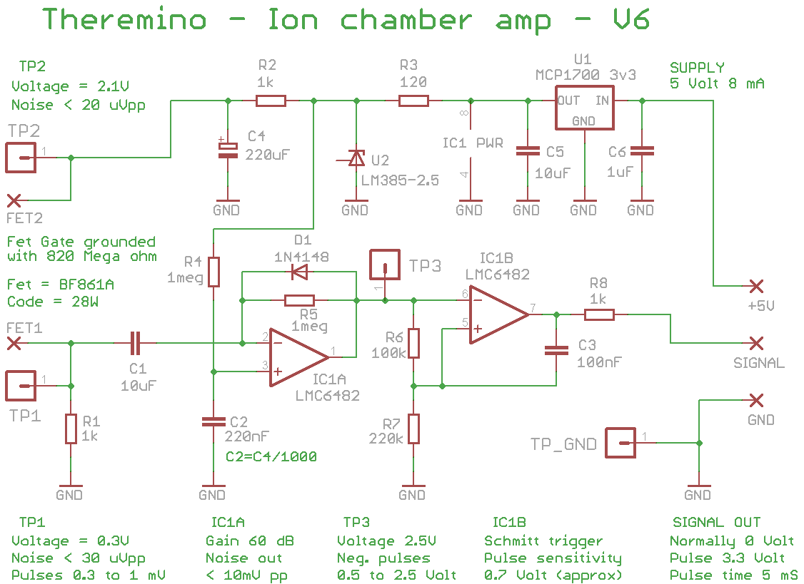
I have a couple of doubts, if an alpha particle generates about 200K free electrons, I should be around 33fA, amplified to 5000 from the FET we should arrive at a pulse on TP2 of 0.165uV, Where I'm wrong?
The preamp stage is a pre-charge amplifier? Here, too, I don't like the theory, Maybe I'm doing something wrong.
Can you give me some enlightenment, please?
Thank you
Because “amplified to 5000”, Where did you find it? ?
I don't know if the 33fA is right, but let's say they are.
– The voltage they develop on the Gate is 33fA * 1 Giga ohms = 33 UV
– And even without doing any calculations, it seems quite normal to me that these 33 uV variation on the Gate produce more or less the same variation on the Source.
– And 33 uV on the source will be multiplied approximately by the ratio of R4 to R1 from the op amp
– Then 33 UV * 10 Mega / 1 k become 330 MV
– And 330 mV is more or less the height of the pulses we measure
Thank you,
I had read in the doc “Radon_IonChamberV7_Electronics_ITA.pdf ” that the FET amplifies by 5000.
Probably the 500 sometimes referred to earlier versions
In reality, the fet does not amplify in voltage but only in current and it is then the op amp that amplifies 10000 times
Another question: both the high pass and the low pass that manifest themselves are centered on the 15/16 Hertz. Correct?
By high pass you mean C2?
It's not really a high pass but it's configured as a charge amplifier.
Anyway, yes. Also acts as a high pass, But I don't remember how often it's, if you want to see all these values simulate with LTSpice, there's the ZIP with the simulations ready.
Hello everyone,
Has anyone tried a parallel platter setup?
Thank you
We have never tried but the electronics could also work in a parallel platter configuration.
If someone wants to try they should pay attention to the following points:
– To use the same electronics and voltage, The distance between the two plates should be similar to the radius of our cylindrical chamber (30 .. 40 mm).
– The plate that is connected to the high voltage should be carefully constructed, with rounded edges to prevent the generation of sparks and well insulated from the external shielding structure.
– The documentation found on the net on parallel plate chambers can be misleading because it always assumes that we use the chamber to measure a current while we use it to count disintegrations.
– The platter that becomes the measuring electrode must be kept far enough away from the external shield so as not to increase its capacity too much in pico farad.
In the cylindrical chamber the measuring electrode was a wire far from everything, while with the parallel plate configuration it becomes a rectangle with a fairly large area. I don't know how much the increase in capacity can affect but beyond a certain point the height of the pulses would be lowered to the point of making it difficult to distinguish them from the noise and detect them. To know how much this factor could affect, it would be necessary to make calculations and then simulations with Spice, or you could try to build one, Measure the pulses with the oscilloscope and compare them with those published in our documentation.
I was thinking of doing it with two overlapping pcbs. A pcb with one side grounded and the other with the 400 volts and the other PCB with one side as the electrode connected to the FET and one side to ground. On balance, the capacitance of the electrode fet with a high voltage electrode is 0,8 Little Farad. Theoretically, the capacity does not seem so high to me.
The two PCBs would be joined by a plastic cylinder lined with aluminum foil.
Everything must absolutely be shielded in all directions outwards.
In other words, enclosed in a metal box (also aluminum but metallic and grounded)
The capacitance between the sensitive electrode and the shield will not be so low unless you have the shield quite far away.
But maybe I didn't understand the dimensions you mean, I was thinking of electrodes of many square decimeters, more or less a large shoebox about 6 cm, so as to arrive not at a liter like ours but at least half a liter.
If you make it much smaller, the capacity would naturally decrease but you would have poor sensitivity.
Another point to consider if you make PCBs is that the copper sides will have sharp edges and corners that can favor the creation of ionization and microsparks.
I thought of making the electrodes circular so as not to have edges, about 6 in diameter. The two PCBs would then be joined by a tall cylinder 4 cm so as to have a 100cm3 volume.
The circular electrodes eliminate the edges and this is fine but since the copper is thin and is cut clean on the edges it creates sharp edges 90 degrees that increase the field at that point. In addition, immediately afterwards there is no air but vetronite where over time a moistened and therefore slightly conductive surface layer is created.
The distance between the electrode with the high voltage and the outer cylinder should not be made of vetronite of the PCB but of air, otherwise a minimum humidity is enough to produce small discharges along the surface of the vetronite. And it takes nothing to produce false impulses.
If the electrodes are far apart 4 cm the cylinder should be at least high 5 or 6 cm so as to leave at least 5 or 10 mm distance between the high-voltage electrode and the shield and one centimeter distance between the sensitive electrode and the shield.
The shielding cylinder should be larger in diameter than copper discs to ensure a certain distance there too, especially between the high-voltage electrode and the cylinder.
And finally 100 cm3 of volume are just a few, you already have to wait hours to get good measurements with a liter and with 100 cm3 you would have to wait dozens of hours.
Hello and congratulations for this amazing project!
I am thinking of making my own chamber and I’ve already sourced some brand new 0.5l cans of 6.6cm diameter.
Do you think they will work as good as the one liter or do I need to lower the high voltage to maintain the 120V/cm field?
Thanks in advance
They should work…
maybe test also with DZ2 shorted to reduce the voltage.
(DZ2 is the easiest to be shorted)
Naturally with 0.5 liters you will have a reduced sensitivity.
Thanks for the reply.
I would be expecting it to be lower sensitivity and I’m okay with that. I’m going to leave them for weekly measurements anyway. I will try to reduce the voltage so I can get the same field as you suggested. Once I complete them I will let you know if my results