
Theremino Automation Language
Simpler than the Basic, easier to Theremino Script. Despite being: “the simplest programming language, in the known universe“, It is even powerful enough. With two or three words, you get results that otherwise, would require code pages.
From version 2.7 You can also bind keys,
for example you can open a web site with a keyboard or launch a video with another.
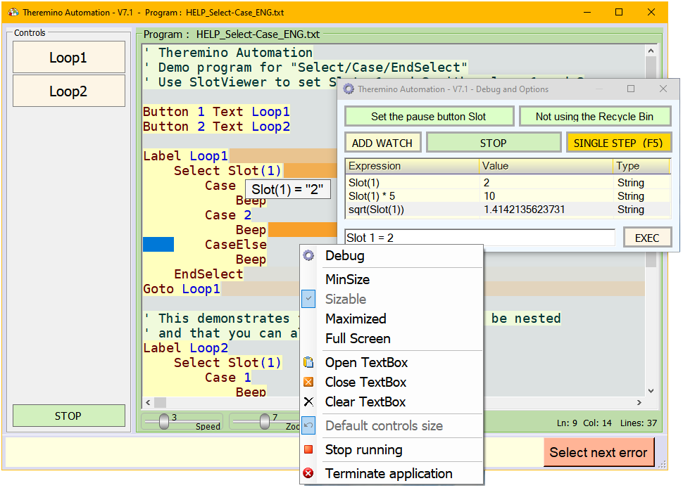
From version 4. x, there are also Breakpoints, the Watches, the “Stepping into”
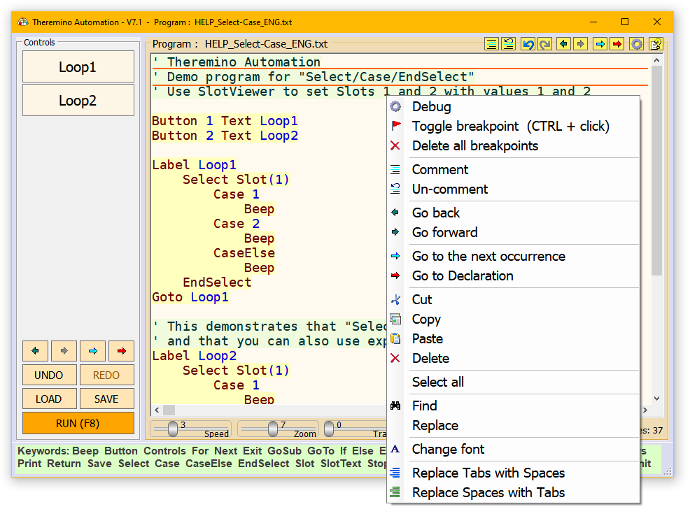
and other new instructions (including the Select Case and instructions to go full screen.
4. x version represents a significant improvement to this application.
Read the documentation to know all the news.
Finally there is also documentation in PDF format, download it from this page.
With version 5.x we introduced variables with names given by the user.
There are also the FOR loops and a large number of new features and improvements.
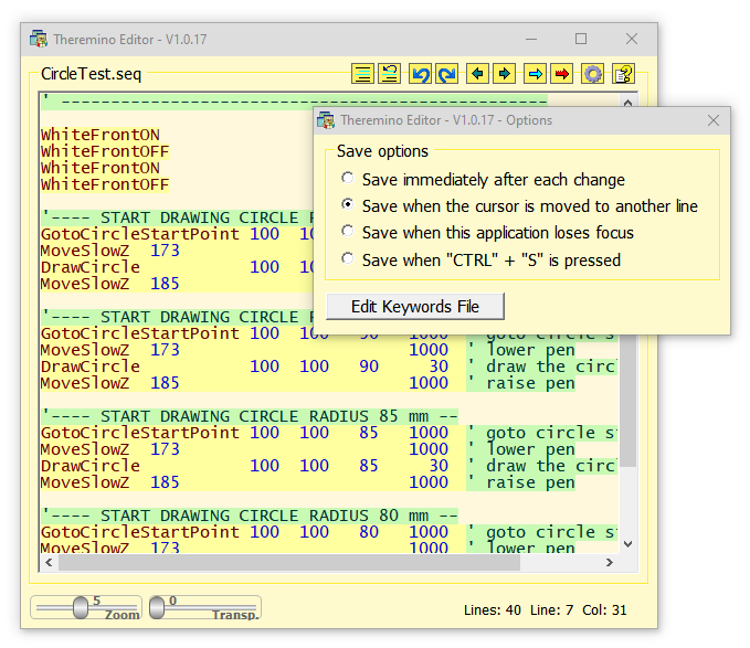
The editor quality in some areas (coloring of errors)
it is also best of the greatest editor, eg VisualStudio.
From version 7 SlotText can also be used to exchange strings between applications.
There are numerous new features and the whole system has been improved for even more comfortable use.
The version 7.1 It contains grandiose improvements – download it !
Automation is becoming a real programming language,
but it remains simple and easy to use
even for those who are not a professional programmer.
– – – – – –
Being able to read and write the slots, You can turn on Led, move Servo Motors, adjust temperatures and levels. But you can also control other applications. For example you can tell Theremino ARM, which GCode run. And then wait, the robotic arm has completed its action, before you perform the next operation.
This is not a real Basic. Only contains functions for automation applications. Don't work too, otherwise it would only, a draft of the Visual Basic. Those who want a more powerful language, can use VBNET or CSharp.
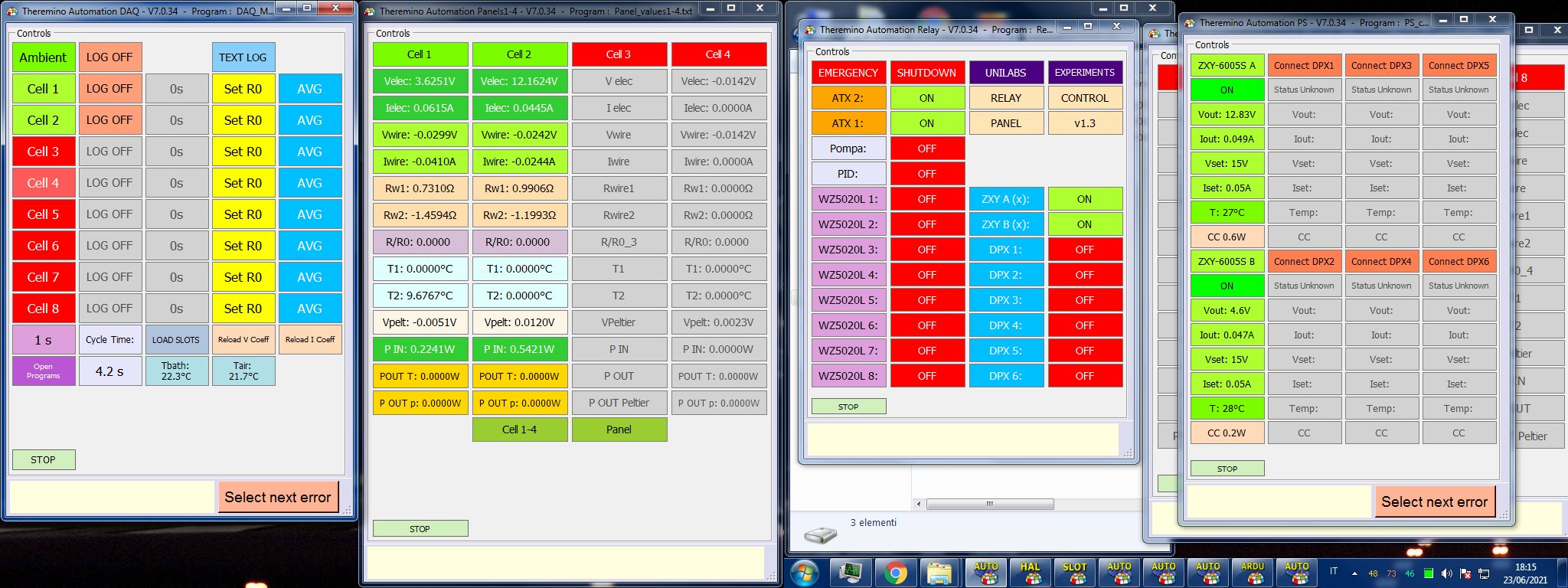
The Theremino Automation is being tested, in a complex automation application. A whole production line in miniature, rapistan, motors, sensors and robot arm driven with GCode. This is an application, that would have undermined a PLC with Ladder. With Theremino Automation has become easy to program and use. Everything is controlled by a Windows Tablet, with the large buttons on the touch screen.
In the last few years (from 2017) automation has been applied to many machines, both for quality control and for the production, especially in China. If we have time we will publish some’ video.
Features:
- The bottom line suggests instructions tailored to what you are writing.
- Error checking is done directly in the editing window with colored text.
- Editing operations are fluid, even with thousands of rows.
- You can also upload images, sounds and videos, to create static or animated mimic panels.
- As far as the language is interpreted execution is very fast. The program lines are running at about ten micro seconds (on average, fast machines). Are 100 000 instructions per second!
Why a new language?
There are dozens of programming languages, one more beautiful than the other. They are fast, powerful and flexible… It seems absurd to have to write a new one. But unfortunately all languages (VBNET, CSharp, VB6, C++, Java, Phyton etc..) require complex techniques and little intuitive even for the simplest operations.
Users expect, at a minimum, You can run an education and be able to specify a wait time, for example 30 seconds, before you perform the next instruction. When they try to write it, the user interface freezes for 30 seconds, the buttons have stopped responding, and the program becomes unusable. We tried to explain, You must use the Thread, the “Event programming” and the “State machines“, but we realized that are overly complex techniques, comprehensible only to those who program for years.
Theremino Automation fills this gap. Basic operations (do something when it happens something else, wait a number of seconds, play a song, view a video, Open a web site, etc…), they are easy and intuitive.
This application is the first step, the evolutionary link, among the bimbominkia and the Maker. From now Theremino the system is at the forefront, in the fight against bimbominkismo!
Applications
Early versions were developed, to control a model of production line with robot miniature painters. Initially it was thought to use a language Ladder, but unfortunately as soon as the project is complicated, the Ladder become a jumble of incomprehensible lines. Then we tried Theremino Script, but the technicians workshop that produces the robot, not being programmers, were difficult to build the structure of Events and Thread, necessary to separate the user interface, the actual automation. Finally the Theremino Automation has allowed, not only to control the robot easily, but also to control the application RobotArm, change the GCode, check about 20 sensors, servo controls, search engines constantly and relays. All this written in fifteen days by non-programmers.

A Windows tablets check out a whole production line in miniature, rapistan, motors, sensors and robotic arm. With four buttons on the touch screen. In these last days, workshop technicians who produce the robot painter, are completing their application with design of animated templates (Thanks to new functions that allow you to upload pictures and videos).
A dosage-filling jars

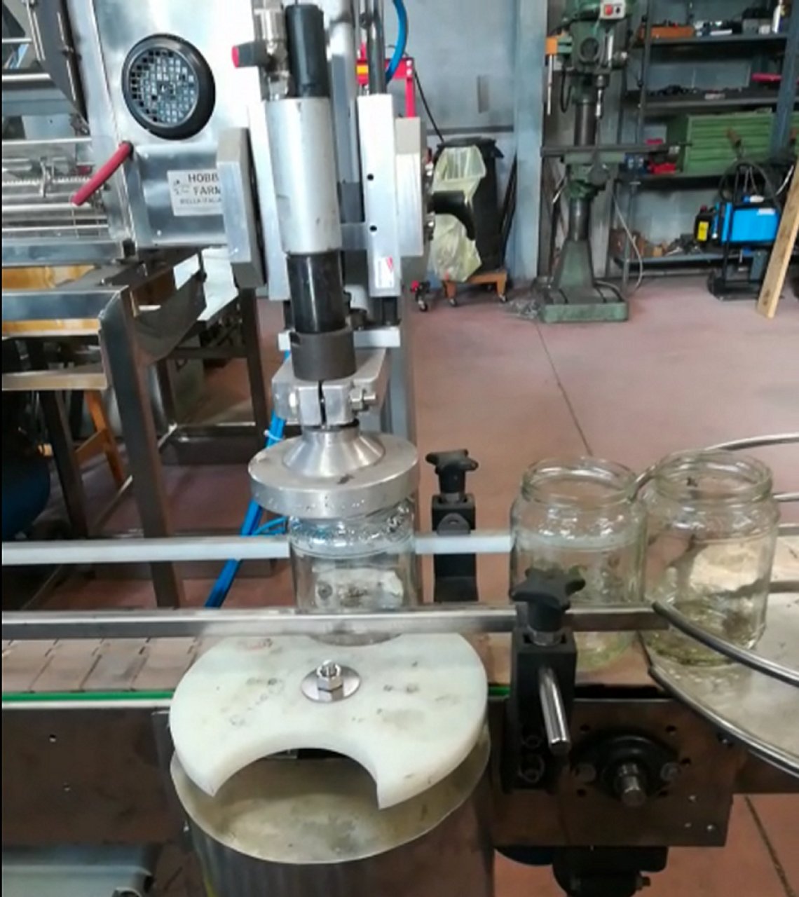
We thank the company Hobbyfarm for this fine example of use of the system theremino. It is a prototype of dosage-filling jars of honey.
Click on This link to better see the details in a video.
An exemplary application
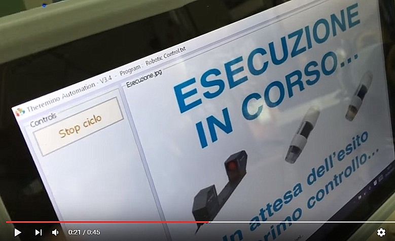
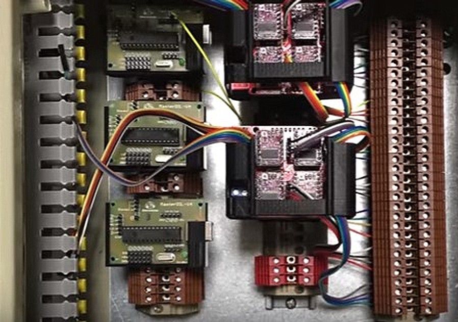
In This video you see a professional application of Theremino Automation and the hardware in your system Theremino. Many thanks Chris for giving us an example so significant and well designed. Wiring the Master modules and drivers is perfect. A very good example for those who must build similar devices.
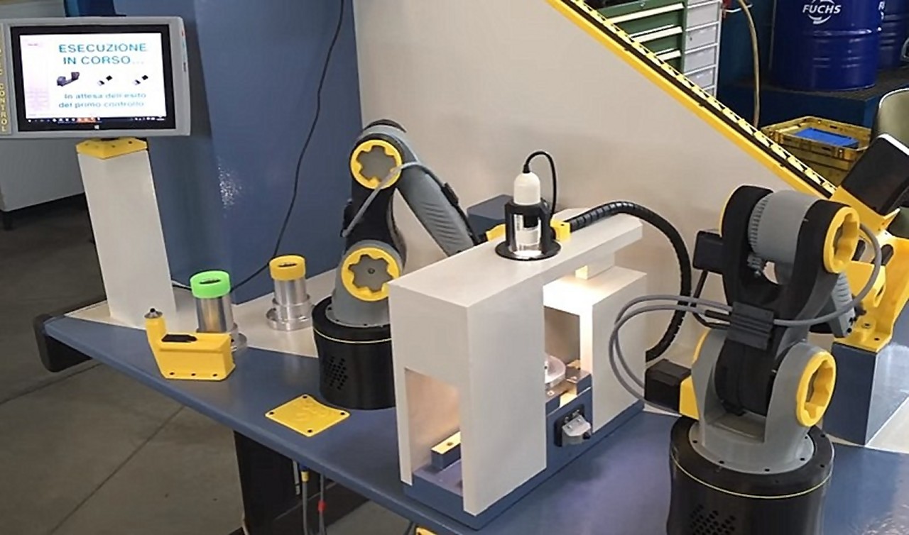
In This second video you see a test of two robotic arms, working in a coordinated manner, led by a simple program written with Theremino Automation,
For more information read the notes below to YouTube videos.
The robotic arms that you see in these videos are built with 3D printer, According to the project Zortrax. Don't follow that plan because it requires an infinite number of time and the results are not satisfactory. We are preparing a chance to build something in DIY, but using toothed belts, plastic gears instead of inaccurate Zortrax project.
Documentation
If it is not updated to the version 7.7, clear your browser cache
Theremino_Automation_Help_ITA
Theremino_Automation_Help_ENG
Theremino_Automation_ODT_and_PDF_Docs (OpenOffice documentation for translators)
Notes for versions
To read the notes relating to previous versions download these files:
Theremino_Automation_VersionNotes_ITA.rtf
Theremino_Automation_VersionNotes_ENG.rtf
Version 7.x
——————————————————————————
THESE VERSIONS CONTAIN NEWS’ SUBSTANTIALS
——————————————————————————
HUNDREDS OF MAJOR IMPROVEMENTS
AND THOUSANDS OF SMALL CORRECTIONS
——————————————————————————
There are so many that it is impossible to list them here
Read the documentation that you download from the previous paragraph
——————————————————————————
Version 7.2
Page 48 – Improved PressKeys with mouse commands (LButtonDOWN LButtonUP MButtonDOWN MButtonUP RButtonDOWN RButtonUP)
Page 57 – Added TTS commands (Text to Speech)
Page 66 – Test added StringContains(String, TextToSearch)
Page 69 – Added cursor position tests MouseX, Y, XP and YP
Page 70 – Added color test functions (GetCursorPixelColor GetPixelColor(X, Y) GetColorRed GetColorGreen GetColorBlue GetColorHue GetColorSaturation GetColorLightness GetColorIndex GetSaturatedColorName GetNearestColorName)
Version 7.3
– Theremino_Automation_V7.3.
– After “Theremino_Automation_V7.3” Theremino_Automation_V7.3.
– After “Theremino_Automation_V7.3” Theremino_Automation_V7.3.
– Theremino_Automation_V7.3() corrected (page 61)
– Theremino_Automation_V7.3() (page 77)
– Theremino_Automation_V7.3 (page 90)
– Page 57 – Theremino_Automation_V7.3 (Read the news in the PDF documentation).
Version 7.4
– When pasting text now the cursor is always positioned at the end of the text. It wasn't easy and it took us years because richtextbox controls do as they please and are difficult to tame. Maybe in hindsight we would have done better to be an editor from scratch.
- Automation from version 7.4 it can also write and read SlotText.
- Automation can also communicate with the new Cobot application, which can receive commands from the outside and also send asynchronous commands to Automation through the "Commands From Cobot" event.
Versions 7.5 and 7.6
– Fixed an error that occurred when reading StringSlots frequently.
– Improvements in button size adjustment
– Passing parameters to functions did not check for all errors
– Double-click during run, NO longer sends the cursor to the start
– Beep-freq-duration on all PCs (without Console-Beep)
– Load CloseApp closes applications even if they are case-insensitive.
– String parameters that you pass to functions must be enclosed in double quotes.
– Resize the controls can be done with CTRL-SHIFT + arrows or + Move Mouse (No buttons).
– The horizontal scroll bar now works well whereas before it was difficult to use.
Version 7.7
– When the application starts, the zoom is the one selected with the cursor
– The button “Select next error” makes a ColorAllLines()
– CTRL-V and Paste do NOT make a ColorAllLines()
– Four Chinese fonts have been added that make Chinese characters more readable
– Fixed Microsoft bug that required auto-selection of whole words
– Eliminated the error that happened if the file was missing Automation.INI
– History now starts blank
– Default controls size disabled when in RUN otherwise it would create problems
– The size of the controls can also be adjusted with CTRL SHIFT and up/down arrows
– Red lines are no longer left by mistake when selecting down and then up
– Sounds are now correctly expected with “Wait Not MediaPlaying”
(try with “Demo ProgramsLOAD and MEDIA functionsTestSound.txt”)
– Wait TTSready works properly
– When you select to the right, the last carriage line is automatically deleted
– The UNDO buttons, REDO and HISTORY now have self-repetition
– Files are loaded and applications are opened even if there are paths in the same folders beyond the 260 characters (But the files and applications you want to open should not have paths beyond the 260 characters)
To use the communications between Automation and the COBOT application, read the following pages in the Automation instruction file:
- SlotText
- Event_CommandsFromCobot
- The commands from COBOT to Automation
- The commands from Automation to COBOT
– Read all the news in the documentation that you download from the previous paragraph –
Download the application
Download Theremino Automation – Version 7.7
Theremino_Automation_V7.7
Theremino_Automation_V7.7_WithSources
For all systems from Windows XP to Windows 10, both 32 which in 64 bit (Linux and OSX with Wine)
Theremino Blockly
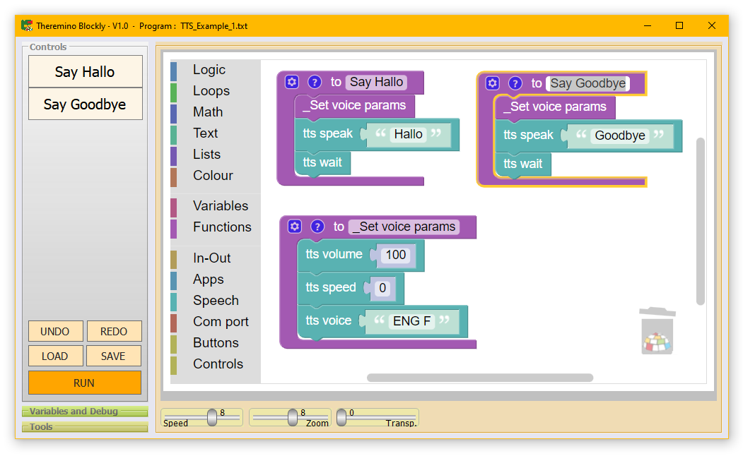
With Blockly you learn to program without having to study the syntax of the commands. Connecting blocks is easy and intuitive even for the little ones and the program is created automatically.
Theremino_Blockly is the younger brother of Theremino_Automation, It's easier but can still access all the main functions of our system, from simple input-output the synthesis and recognition vowel, to the control of robots cooperative, to the measure of radiations he was born in radon, the control of Arrhythmias Heart, at analysis Chemical, measures with Oscilloscopes and Analyzers by spectrum, etc…
In This page Find an index of (almost two hundred) Applications of our system, all Free and Open-Source.
The files that draw the blocks are derived from Google's Open Source project and are executed by Microsoft Edge. All necessary files are already present both in Windows 10 that in Windows 11, without installation and without connecting to the Internet.
Documentation
This documents are in PDF format, the same that you download with the application.
Theremino_Blockly_Help_ENG.pdf
Theremino_Blockly_Help_ITA.pdf
Theremino_Blockly_Help_CHN.pdf
Theremino_Blockly_Help_JPN.pdf
This is the original documents, OpenOffice format, for translators.
Theremino_Blockly_OpenOffice
Versions
Version 1.2
– The folder where the Blockly.exe file is located contains only the DLLs actually used.
– Commands from Slots are executed even if there are only functions, without the relative buttons.
Version 1.3
– Now you can edit the names even if there are more than 16 Blocks.
Download the application
Download di Theremino Blockly – Version 1.3
Theremino_Blockly_V1.3
Theremino_Blockly_V1.3_WithSources
This application and Theremino_GPT are the only ones in our system to work only on Windows 10 and Windows 11 (and maybe even Windows 7, but we didn't try it). In addition, those who want to recompile them will have to use Visual Studio 2022 Community (free).
These limitations are due to the heart of Blockly, written by Google, which only works on the latest versions of browsers and therefore forced us to use WebView2, i.e. the same functions used by the Microsoft Edge browser. And this, chain, forced us to use Visual Studio 2022 this is noticeably slower and more cumbersome than visual studio 2008.
Theremino CNC

The CNC Theremino application is designed for easy. There is only one system of coordinates, you bring the cutter start point, Reset axes and off we go. Basically how it works is all here.
But this simplicity should not suggest poor results. The calculations are done with precision and good results are.
Those who were not happy with this simplicity, could exploit the precision impulses, generated by our firmware, even with Mach3. Since Mach3 does everything and more (Note 1), can definitely send the coordinates, our Slots. The difficult, like everything else about Mach3, It will convince him to do it (probably with a PlugIn).
(Note 1) Mach3 tries to do everything (even the most abstruse options, He never uses anyone) and this makes it difficult to use for everyone. His behavior is so complex, that often no one knows, If you are doing what you believe, or something else. With Mach3 also make the Skin is hard! Sometimes Mach3 files are damaged, and control panels do not open more, but the files are written in Sanskrit (XML) and are difficult to read and correct. For these reasons, We decided to write Theremino CNC.
Colors and shapes (Skins) user-modifiable
 << Click on the image to see the skins
We have been criticised for neutral colors too of our applications. Since it is hard to please everyone, We've added the ability, to change the colors, that the form controls. Theremino CNC has already twenty Skins ready. To change skins (even in process), just press the button “Selected skin”. Who is not pleased, can change the color files. If that wasn't enough, the images in the folder Skins are changeable. But you can also add new images and create new skins.
Combined machines
Theremino CNC leverages the modularity of the system Theremino and has inputs and outputs on slots for each type of sensor and actuator. Unlike other CNC applications, they are designed for a specific purpose, You can easily build machines “combined”, exploiting the same mechanics to do more processing. In this way the same engines and the same mechanics (which are the most expensive parts) can be used for CNC mill, that engraving with laser, that for 3D printing and also for special machines, as, for example,, polystyrene cutting.
Good examples of variation, than the usual three-axis CNC, are foam cutting machines, visible in the following videos and links:
https://www.youtube.com/watch?v=tjPG4KdE7Mg
https://www.youtube.com/watch?v=ayC2gRUJn8o
https://www.youtube.com/watch?v=_S2smZKZWRI
https://www.youtube.com/watch?v=NCjrHcDag6w
RCGroups – Interesting forum for manufacturers of radio-controlled models and drones.
Harjit Singh – Forum on foam cutting with CNC Theremino. The thread contains much useful information and excellent pictures to achieve a four-axis hot wire mechanics.
Accuracy of coordinates
The boxes that indicate the position of the axes, show three decimal digits after the decimal point. This serves to facilitate reading, but the calculations are made in “Floating point double precision” (with vectors in 5 dimensions). And also the coordinates of GCode, are read with all the decimal digits available (up to 16 decimal places). This accuracy might appear overwhelming, but assures us that in every situation the results are perfect. Read this article, that shows the inaccuracy of Mach3, for very small (the two photos comparing).
Functioning on older computers
Both Theremino CNC Theremino HAL work well on any computer or notebook, from WindowsXP to Windows 10, both 32 that 64 bit.

Here you can see the computer that we normally use in lab, to make the PCB with the cutter Proxxon. This is a notebook, in operation for over twelve years, with Windows XP, Celeron processor single core, little cache and outdated video card. From little memory that there is (1GB), the video card eats 300 Megabytes, leaving only 700 Megabyte per OS. In these prehistoric conditions, HAL travels to over 400 FPS (may be even more, but have been limited by “Comm speed = 10”) and Theremino CNC moves fluidly engines, while upgrading the graphics of the toolpath and translates to follow the processing. Finally you can see, at the bottom right, the icon of “Task Manager” (green square), that indicates a CPU consumption by about 30%.
Theremino CNC native USB Adapter or?
The old machines, suitable for Mach3 or LinuxCNC, were usually connected, through a “Parallel port”. Today, parallel ports are virtually extinct, and you need to simulate, with expensive PCMCIA adapters. In addition to the steps, one by one, directly to your PC, leads to a great instability of impulses, see this section. To connect the machine via USB, you could redo his wiring, and granted an Master and USB port. Or you can disconnect the cable from the parallel, connect it to a Theremino CNC Adapter, and start working right away.
Which controller to use for stepper motors?
I definitely avoid costly cnc-controller with drivers welded on one plate. The first flaw you have to throw the whole controller. So you spend a lot, You'll waste and pollute, even going against our rules to limit waste. A good solution is to use drivers with the connectors, so you can substitute or add to increase the number of axles.

Do not be fooled by salespeople who do not publish schematics and “Let think” that their drivers are better. When you go to check the chips are the same as these drivers, It's always great A4988 (or equivalent) products from Allegro.
More information and diagrams in Notes on Controllers and on the Driver Board.
Driver Board – A support base for drivers
Don't buy expensive cnc-controller with the chip directly soldered on board! The drivers must always be replaceable, as in Driver Board of these images.


To accommodate the drivers, suggest that you remain completely modular, with all the components individually replaceable, in full respect of our our principles to limit waste.
More information and diagrams in Notes on Controllers and on the Driver Board.
Affect PCB
Among the sample file Theremino CNC there are virtually all printed circuit boards of the system Theremino, If they were missing ask him via email or blog and will add them.
GCode files were written by FastGcode extension that we wrote for Eagle and Eagle files in downloads of all projects.
FastGcode and some explanations for Eagle are here:
https://www.theremino.com/downloads/uncategorized#eagle
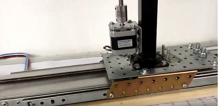
The way we do PCBs (prototypes) provides insulation from 0.8 mm, for which you can carve only PCB with components not too small. All integrated DIL are fine and you can easily use SMD components (dimensions 1206 and 0805). If you carefully cutter, taking the zero a little’ high, You also get to chip SOIC.
Millers Proxxon
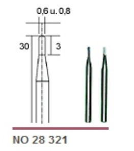
The cutter we use is normally a Proxxon 28 321, readily available in Brico Center. A pack of two cutters (0.6 and 0.8 mm) cost around eight euros. Unfortunately the 0.6 mm it breaks too easily, but with the 0.8 you do everything in a single pass (scontornamenti, holes and final cut).
We used these Proxxon for years until we discovered that there is better at reasonable figures.
Best cutters of Proxxon
Since we discovered this is all another go.
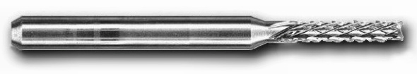
- This is the model 626, Diamond 0.8 mm.
- Perfect size.
- Has the flat tip and leaves background that seems to be made with photo-etching.
- Leaves no curbs between one coat and the other. With the Proxxon you had to use an overlay from 0.2 – 0.3 mm in order to prevent remained burrs, with these cutters you can minimize it 0.1 or even 0.05 and the processing time is cut in half.
- The edges of the runways are so clear that you should not even more pass the final glass paper.
- The holes are perfect almost like they were made with the drill bit.
- Even after many PCBS continues to cut fine.
Buy go here: http://www.mjcnc.com/fresa-626.html
(4.5 Euro + 8 Euro shipping. Then 5 pieces 30.5 Euro)
We guarantee that it is not advertising, the company mjcnc does not even know that we have them linked. Maybe we'd get something if they knew. But we don't have time to collect loose change in this way, We have other ambitions, one of which is to keep this site “clean”, totally no ads. Because we're suggesting then? Because we would rather discover them five years earlier and we regret that others can be in the same situation.
Update Theremino with a new version
When you download a new version do not overwrite your configuration file, both the CNC of HAL. A surefire way to not lose anything you copy the folder ThereminoCNC root, who then will become "ThereminoCNC.". -Copy ", then overwrite everything and then go get their configurations from folders of copy.
Personal configuration files, by conserving and restoring, are:
Theremino_CNC_INI.txt
Theremino_HAL_ConfigDatabase.txt
Theremino_HAL_INI.txt
Te mperatureTables.txt
If you switch to CNC 5.4 you need to take the parameters of the PID from the new TemperatureTables file
Downloads
PRE-RELEASE – Version 3.27 – The documentation is approximate and only in Italian. Two new versions of Look Ahead, allow not to cut curves, without the heavy penalty of time, caused by ExactStop. To zero and Home commands are not yet working. Display the Toolpath contains inaccuracies that we will put in place soon.
PRE-RELEASE – Version 3.28 – In the previous version contained a LookAhead error (the last segment of the file was calculated wrong). Now the two have become one LookAhead, simplified and well tested. To zero and Home commands are not yet working. Display the Toolpath still contains inaccuracies, We will put in place as soon as possible.
PRE-RELEASE – Version 3.29 – Display the Toolpath is yet to improve. The two buttons “Calibrate” are to be finished. Nine pages of help are to be finished. Everything else is OK.
PRE-RELEASE – Version 3.30 – In 3.29 There was a major bug, After an M-zero, the spindle motor not relaunching and there was the risk of breaking the tool. Now this error is fixed. Display the Toolpath is yet to improve. The two buttons “Calibrate” are to be finished. Italian help is finally complete.
PRE-RELEASE – Version 3.31 – Display the Toolpath is almost over, now correctly indicates the first segment and provides new views for the axes A and B. The two buttons “Calibrate” are to be finished.
PRE-RELEASE – Version 3.32 – The two buttons “Calibrate” are to be finished. Everything else is in place. Speed changes during JOG are resolved. Many small inaccuracies are corrected. Now you can upload files by paths as desired, also not contained in folders Theremino CNC.
PRE-RELEASE – Version 3.33 and 3.34 – The buttons “Calibrate” have become three. The calibration adjustment page is over. The new Enable signal OUT is working. The Help file is updated. Still need to finish my reading peaks and compensation at the end of calibrations. If nobody invents new things to do, in a few days we will finish it.
PRE-RELEASE – Version 3.35 – Added the Zeta axis with the Z and X keys for keyboards without PageUp/Down. Added the ZOOM buttons for on ToolPath. Fixed closing of the panels when the mouse leaves the. Improved the text of the title of the Message Box. The new Enable signal OUT is not enabled if you throw a right application “In OUT enable” disabled. The Help file is updated. Still need to finish my reading peaks and compensation at the end of calibrations. If nobody invents new things to do, in a few days we will finish it.
PRE-RELEASE – Version 3.36 – Speed also negative for spindle anticlockwise. Completed calibrations. The button “In OUT enable” can be disabled to experiment without engines and without losing its alignment with the machine.
PRE-RELEASE – Versions 3.38 and 3.39 – Zoom the Toolpath is much improved – The Pan is dragging with your mouse – You can use a GamePad (even Wireless) for Joggare and for the main functions – When the Toolpath is maximized automatically follows the processing – Many more improvements ... It is worth to read all the instruction file.
Version 4.0 – Innovations are so many that it is impossible to list them here. Read the documentation files. All required functions in recent months are implemented, even temperature control, for 3D printers, is complete. Now you can also check out the weirdest machines, Laser engravings, polistitrolo cut, etcetera…
Version 4.1 – Small improvements on the location of the keys and the minimum size of the window. With this version you can work also on XP and on computers with small screen and video drivers particularly strange.
Version 4.2 – Eliminates the need to install DirectX!!! And also delete the flashes occurring during startup.
Version 4.3 – Small fixes in documentation. Deletes the CustomControls.dll facing problems in Linux and Mac
Version 4.4
– Jog movements are stabilized, the speed is slightly faster and not they Meow more.
– New menu options with FirstSlot and JogSpeed for “Normal, Shift, ALT and Ctrl”.
– Adjustable delay for spindle motors that start slowly.
– Ability to open and save the GCode also through the local area network.
– The codes are also mentioned in the following lines G02 and G03 (Gcode test Riccelli).
– The documentation has improved and fixed a reference slots 33 (who were appointed 27 by mistake).
Version 4.5
Replaced Theremino HAL with version 7.0 (the version 6.9 gave errors changing Pin type).
Version 4.6
– The selected line of GCode (highlighted in blue) now lies at the Centre of the visible area.
– The new command “SlotSkipInput” (Slot 34) terminates the running line and goes immediately to the following. You can use it, for example,, to finish the descent of ’ Zeta axis and make holes of constant depth, on materials of irregular thickness.
– The new “Low acceleration compensator” (Options menu and Appendix 26 Help file) allows controlled tolerances even on machines with low acceleration.
– The “MainEnableOutput” (Slot23) now properly set even when starting the application.
– The code M84 now in addition to the Slot 23 (Enabling machine overall), also disables the button “In OUT enabled”.
– The Slot “Emergency” and the space bar now interrupt l ’ running at all times and not just during processing as in earlier versions.
– The Slot “Emergency” and the space put to zero all control signals of external devices.
Version 4.7
– Added message “Press OK” in the calibration, This will read the fee before you reset.
Version 4.8
– The message “Press OK” in the calibration had caused a very strange problem, the SHIFT stopped working. Now to get them re-run after calibration there is a “Flush” total of the keyboard. This looks really a bug of Windows, It is not easy to find because Windows is free from minor defects of this kind, but maybe this time we found one.
Version 4.9
– The “Speed” is resetted by closing the application, so not happening rather than to start the spindle take a turn.
– The lines G02 and G03 also accept errors, for example, R = zero. Of course the curve does not run but the application no longer crashes with an error.
Version 5.0
– Versions 4.4 the 4.9 contained a mistake that slowed the movements at every turn. Now the movements are fluid again, as in versions 4.3 and earlier. Furthermore the processing times are very short, in some cases almost halved.
– Fixed horizontal scrolling after running a Load-Gcode.
– Added CoreXY mode – see : http://corexy.com/theory.html
– Added signal sounds at the end of processing.
– If the master loses connection the STOP button is written “Master error”.
– If the master loses connection processing is stopped.
– The command GotoZero XY axis moves first and then the z-axis.
– The command GotoHome moving before the z-axis and then XY axes.
– Now you can run the GCode Step By Step (one line at a time).
– The options are extended with many commands including the direction of CalibrateZ.
– Now with the keys F5 (RUN) and F8 (STEP) You can start the Gcode, stop it and run it one line at a time.
– Now you can use the keys on the keyboard and Joystick even when machining is paused.
– These variations, and other minor, are explained in detail in the documentation.
Version 5.1
– In some cases it could happen that he could not do with the zeroing distance running sensors. This happened if the “Steps Per Millimeter” set HAL were particularly low (100 or less). You should never find themselves with “Steps Per Millimeter” very low, if it happens it is good to increase microstep. However, this error was corrected and does not happen more problems even with very low values. However, keep the “Steps Per Millimeter” at least in 20.
– We reversed the F5 and F8 working to bring it to the Automation and standard Microsoft applications. So now F5 and F8 = = STEP RUN.
Version 5.2
– The break for the spindle motor start now issues a message with countdown.
– The break for the spindle motor starter may occur in the change from “Rapid” to “Work”, or after the M03 code, M04, M13, M14.
– The very long file upload is accompanied by a message on hold.
– Previously very long GCode file (than ten thousand rows) slowing the execution. Now the execution is also smoother with millions of lines file.
Version 5.3
– Now you can also use the IOT-HAL instead of the HAL, it just needs to be in the folder.
– You can open GCODE files from the command line
– If the CNC is opened twice by mistake, the second opening is deleted.
– HAL applications are not opened twice if they are already open.
– SpeedMax and AccMax added in options (adjust them equal to the values set in the HAL)
– When the limit switches act, you can move with SHIFT + Keyboard arrows
– Improved time calculation. It takes into account the acceleration and also in part of the LookAheads
– Adjusted M05
– Improved temperature control.
– Improved temperature tables. Now you can also set the PID parameters.
– The first movement after waiting for the spindle to start is performed correctly.
Version 5.4 (April 2023)
– Added SpeedMax and AccMax options that
– When the limit switches act, to unlock you use SHIFT + Keyboard arrows
– Added PID parameters for temperatures
– The MoveTo command 10 20 now moves only the X and Y axes
– The MoveTo command — — 30 now move only the z-axis
– Rotations now act around zero or around the lower-left corner.
– Added options “First Slot” and “First TextSlot” To set up communication slots
– The complete list of commands via SlotText and tips for using them are in the Appendix 27
– Now you can execute commands sent by other applications. An entire process can then be automated., for example using a robotic arm and an application that controls both CNC and arm movements.
– Among the most important commands is the ability to start a GCode, pause it, Stop, run a part or even a single line, upload another GCode, Change speed parameters, Go to default locations or locations that you specify in the command itself, Reset, read the status of the machine, etc..
Version 5.5 (March 2024)
– Now the path to the GCODE file is stored in its location and the file folder is retained even if the file is not found.
Version 5.6 (April 2024)
– In the versions 5.4 and 5.5 the two DirectX DLLs were missing, so on many Windows they gave an error and did not open. The version 5.6 Corrects this issue
– – – – – –
Versions 5.x contain significant improvements.
download the 5.6 and replace the version you are using.
To keep the same settings from the previous version
You should copy the following files, from the old version:
“Theremino_HAL_INI.txt”
“TemperatureTables.txt” (but update the pids from the new file)
“Theremino_CNC_INI.txt”
You must overwrite the new version files
as also explained in the previous paragraph.
– – – – – –
ATTENTION
In the versions 5.4 and 5.5 the two DirectX DLLs were missing
so on many Windows they gave an error and wouldn't open.
The new version 5.6 Corrects this issue.
Download Theremino CNC – Version 5.6
Theremino_CNC_V5.6.zip
Theremino_CNC_V5.6_WithSources.zip
For all systems from Windows XP to Windows 10, both 32 which in 64 bit (Linux and OSX with Wine)
This application could not start because it uses DirectX. If you need to download the DirectX version, We recommend and follow the installation notes.
Documentation
This documents are in PDF format, the same that you download with the application.
G_and_M_codes_ITA.pdf
G_and_M_codes_ENG.pdf
Theremino_CNC_Help_ITA.pdf
Theremino_CNC_Help_ENG.pdf
This is the original documents, OpenOffice format, for translators.
G_and_M_codes_ITA_OpenOfficeDocument
G_and_M_codes_ ENG_OpenOfficeDocument
Theremino_CNC_Help_ITA_OpenOfficeDocument
Theremino_CNC_Help_ENG_OpenOfficeDocument
These are two videos on the new speed stabilizer (explanations in the help file):
ThereminoCNC_V3.31_Without_Stabilizer.avi
ThereminoCNC_V3.31_With_Stabilizer.avi
Theremino Replicator

“Theremino Replicator” – alias “3D Printers” It was swallowed up by Theremino CNC. And the same happened for laser cutting machines, for engraving and cutting of polystyrene with hot wire.
We maintain this space which will probably be filled with “Theremino UvPrinter”
UvPrinter?
It will be a kind of “Ultraviolet Stereolithography” but you will call STL, because it is a horrible name. In STL “Stereo” There's just nothing and lithography was a completely different process.
In essence, the application Theremino UvPrinter will be used to build machines that polymerize a resin with ultraviolet images. The result is to create objects much quicker than with 3D printers. But also the ability to create incredibly accurate details. Also the mechanics are simpler, don't need three orthogonal axes, but a single axis that rises and falls.
Theremino QRcodes
This project consists of two applications Theremino QRcode and Theremino QRdecoder, that encode and decode all types of QRcode (square labels) and BarCode (barcodes).
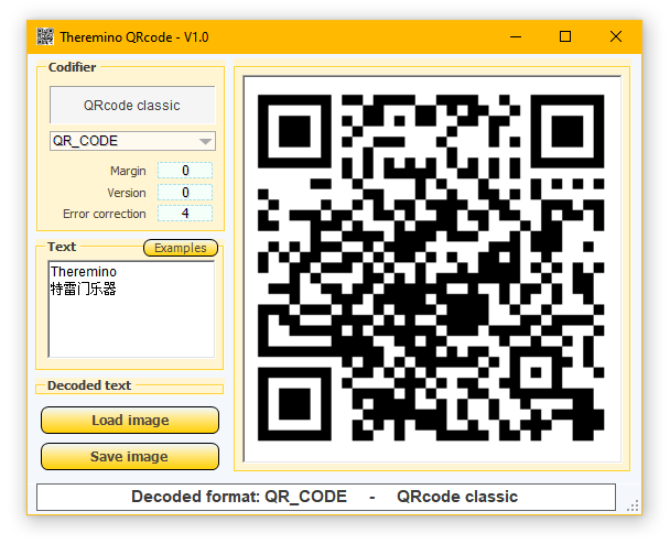
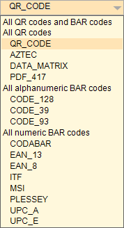
Fifteen different types of codes can be used, four QR codes and eleven barcodes, of which three alphanumeric and eight numeric.
Both the encoder and the decoder are very fast, so while writing in the coding application, you see the graphics of the code that change and at the same time you also see the decoded text that changes immediately in the other applications.
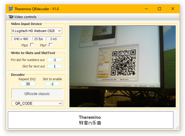
The QRdecoder applications, as well as sending the decoded text to a SlotText, it can also decode numbers found in the text and send them to numerous numeric slots. In the text of the code you have to write for example: “Slots 33 44 55” and numbers 33, 44 and 55 they will be sent to three successive Slots, starting from the slot indicated by the box “First slot”.
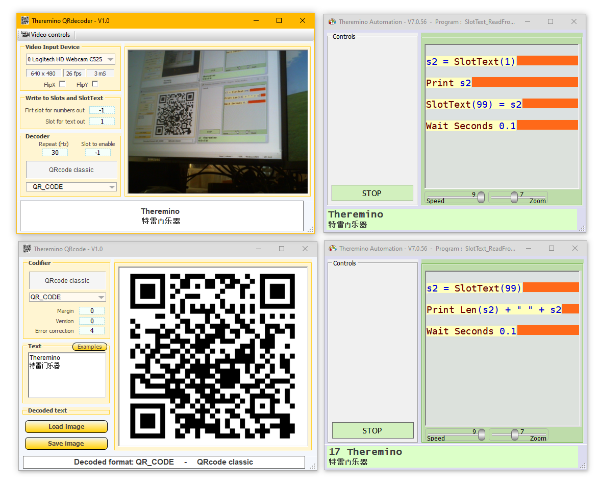
In this last image you can see the QRdecoder application that decodes the text and sends it to the SlotText 1, which is then read by a Theremino Automation application (at the top right) which prints it on its bottom line.
This image also highlights the possibilities of transfer strings between applications by means of SlotText. In fact, the upper Automation Application copies the decoded text on the SlotText 99 and the lower Automation app reads it. Finally, the latter prints a number on its bottom line which is the length of the text in characters, followed by the text itself.
The image encoding and decoding operations are carried out by means of the ZXing bookstore which is Open Source and totally free, without any conditions.
Download di Theremino QRcode e QRdecoder
Theremino_QRcode_V1.1
Theremino_QRcode_V1.1_WithSources
Theremino_QRdecoder_V1.3
Theremino_QRdecoder_V1.3_WithSources
For all systems from Windows XP to Windows 10, both 32 which in 64 bit (Linux and OSX with Wine)
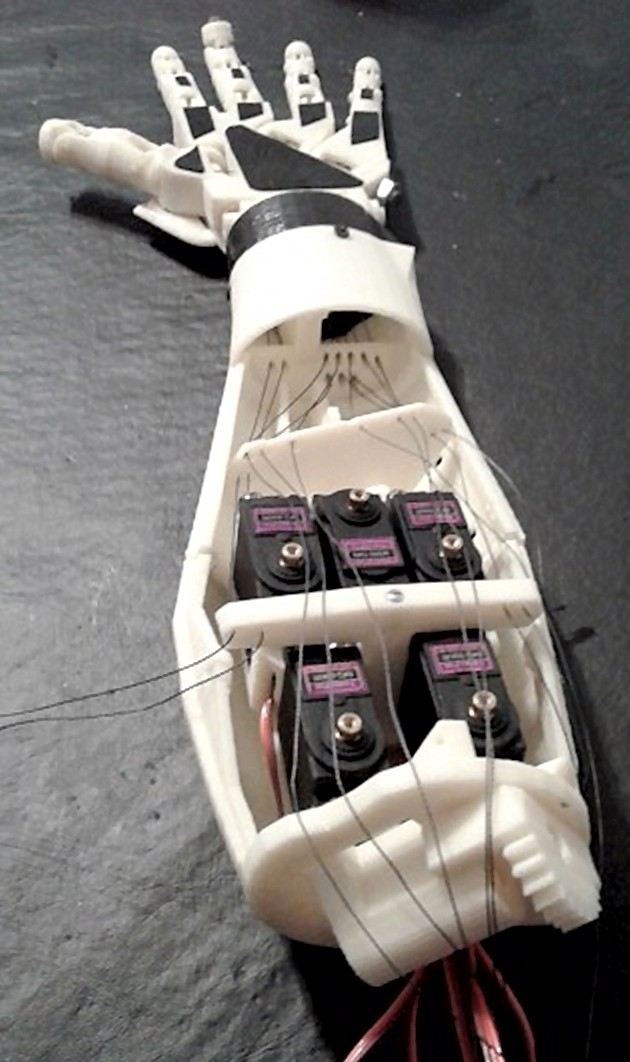
Theremino Arm

This is the program to control a robotic arm. Currently only implemented four joints, but everything is ready to expand or modify the program, for all kinds of similar applications.

Those who want to experiment with the construction of robot arms, can use this program as an example, and as a collection of useful functions. But keep in mind that it is undertaking a very challenging project, where there are many things to learn and understand. It will take a long time before you build something that moves in a meaningful way.
Even the calibration of the lengths and angles is a difficult task, that requires you understand what you are doing. If the settings aren't accurate, the tip of the arm does not move out of orthogonal planes and parallel to the base plane, the rectangles become trapezoids and straight lines become curves.
If you need any advice please. To facilitate the first experiments we will give you information on the particulars of the small arm writer we built for trial and that you can see in action on the page Video and Images
Mechanical construction
In this file you will find the construction details for a small robotic arm (the draft submitted to the contest make4cash of the magazine OPEN SOURCE ELECTRONICS)
Robotarm (PDF file with mechanical and electrical details).
To improve the accuracy you could try the servo DS8231 visible here:
www.theremino.com/hardware/actuators/motors
These servo costing quite (about 70 Euro), but they promise performance five times better than TGY930. We tried them not so please, for pleasure, the results of your any experiments.

The Link1, linking the second motor with the third, can be realized as in this picture. Eliminating plastic cruises you get greater rigidity.
– – – – – – –
Use of parameters that are not explained in the instruction file
- Rapid (mm/min) – Top speed for the rapid movement in millimeters per minute.
- Work (mm/min) – Maximum speed during processing (with tip touching the surface), in millimeters per minute.
- Max error – Maximum error (approximately in millimeters). Decreasing this value the movements slow down. In addition to some point can only be slowdowns and no improvement in accuracy. Indeed you will get straighter lines, with high enough speed and “Max error” exceeding “1”.
- Override Z – By enabling this parameter values for Z (height) the GCode are no longer used. In place using two fixed heights: “Zup” and “Zdown”.
- Z trip level – If the Z-value of Gcode exceeds this value using “Zup” otherwise “Zdown”. Usually held at zero, except for GCode details.
- Z up – High level, for rapid movement, with tip that does not touch the surface. It takes place in a few millimeters from the surface, to make sure you don't touch it by mistake. Increasing this value increases security, but the work is slowed.
- Z down – Low level, for movements of work. Usually held at zero.
- Gcode automation slot – Other applications can control the change of Gcode writing integers in this slot.
-1 = Stop and rewind the GCode at the forefront
0 = Pause
1 = Loads and starts the first Gcode
2 = Loads and starts the second Gcode
3 up to “N” = Loads and starts the Gcode following. The GCode must be located in the folder “Theremino_ArmMediaAutomationFiles” and are used in alphabetical order. To establish their order we recommend that you call them 01-Name / 02-Name / 03-Name etc…
- Automatic parking position – Enabling this checkbox your arm automatically returns to the parking position during breaks.
– – – – – – –
Notes for versions
Version 1.3 – minor improvements including reading files with or without line numbers, with any separator and in all the usual formats.
Version 1.5 – other improvements such as the variable scale for the graphics and the visible version number in the title of the application.
Version 1.6 – improving the accuracy of design by adding a small delay at each lift pen to allow the engines to get in position, now the circles close better.
There’ was a mistake of numbering and many intermediate versions have not been published for the 1.6 you jump directly to version 2.7.
Version 2.7 – Great improvements! – Who built a RobotArm must upgrade to this version. The algorithm for creating the path and’ completely redone, drawing speed and’ increased tremendously without loss of precision. www.youtube.com/watch?v = S8aXLacX14s Some minor inaccuracies in the drawing (circles that don't close properly) are completely resolved. The parameters are more’ easy to understand and’ also a handy preview of the image generated by the Gcode.
Version 2.11 – SCARA and Delta and many small improvements.
Version 3.1 – Improvements in the algorithms of Scara and Delta configurations.
Version 3.2 – Deleted the error that occurred when opening if the last time ThereminoArm had been closed by minimized. Fixed a bug that was significantly slow down the Bill if not enabled “Override” and with some Gcode. Load correctly the Gcode when loading a config.
Version 3.3 – Fixed a small miscalculation. You should notice a slight improvement in the position of the start and end points of each segment (When the pen is lifted and when lowering and start typing)
Version 3.4 – Added on “Panic button” with the “Space bar”. Added the status bar with some error messages (unrecognized codes and Panic). Improved reading of Gcode who does not deceive unrecognized codes (G2, G3 and G17)
Versions 3.5 and 3.6 – Fixed small defects were born during the transition from XP to Windows-7/8.
Version 4.2 – Added on “Gcode automation slot” and the boxes to disable the fourth engine and automatic return to the initial position. Eliminated many small errors. This release collects all the improvements of recent months. Download!!!
Version 4.4 – Many small improvements.
Version 4.5
– Added ability to use Stepper Motors.
– If you enable the button “Stepper” then the slots are used one and one no (Steppers using two slots each).
Download Theremino Arm – Version 4.5
Theremino_Arm_V 4.5
Theremino_Arm_V 4.5 _WithSources
For all systems from Windows XP to Windows 10, both 32 which in 64 bit (Linux and OSX with Wine)
InMoov – An Open Source robot and 3D printed

The robot InMoov is fully compatible with the system Theremino, replacing the Arduino with the Master, you gain space, you spend less and increase communication speed (of course you should know how to tinker with the software as explained below).
This is an interesting case of parallel evolution! Two totally separate projects (Theremino and InMoov) they came to the same conclusions (the same operating system, the same supply voltage, the same connectors, the same cables), so as to be fully compatible electrically.
The InMoov control is carried out by means of a touch-screen tablet with Windows 10. The designer of InMoove "Gaël Langevin" writes: “… dfter many tests with the OdroidU3 and the Raspi2, I came to the conclusion that ARM processors are too slow …”
In the middle of this video shows tablet with Windows10:
https://www.youtube.com/watch?v=b3O45Gr71bk
Also interesting to note that InMoove uses normal servo for all movements. For each arm, where the stress is greater, USA 4 servant HS805BB from 24 Kg in parallel. For the other movements use smaller servant.
– – – – – – –
ATTENTION: This is a very complex project. Before you start construction it is good to do many experiments by connecting some simple Led and Servant to a Master. You will need to know the application HAL, the Viewer and slots. Then, to program the movements, also need good foundations of programming with Theremino Automation or even better with Visual Studio Express 2008, or with Python that is the language of choice by “Gaël Langevin ".
Those who know the system Theremino, It can use the masters to generate signals for Servant. In this case the Slot numbers will be different from those of Arduino and you must have enough experience to remap all sensors and modify the software properly. Those unfamiliar with programming and electronics, would do so better to follow the original design and use Arduino modules, instead of the modules Theremino Master.
To start with something simple you can start from a finger, as explained on this page:
http://inmoov.fr/finger-starter
Here is a list of images with the mechanical fittings:
http://inmoov.fr/gallery-v2
And this is the list of materials, with recommendations and explanations :
http://inmoov.fr/default-hardware-map
Theremino Radar

An interesting application developed by Mauro Riboni. Based on an ultrasonic module of type HC-SR04, works surprisingly well and provides a display similar to that of real radar. Here you see a YouTube video: http://youtu.be/FsW4qwXvpB4
Unfortunately very limited features ultrasonic modules. The maximum distance is a few meters and the RADIUS is wide 30 degrees. (but the sensors are suitable for systems tighten it a bit) hardware/inputs/sensors # usound
Although ultrasound technology is only suitable for educational applications or toys, Likewise, the application Theremino Radar is very interesting, with small changes you could adapt to the microwave sensors or lasers.
Mechanical construction
One servo for model airplanes directly driven by an ThereminoMaster PIN, wheel the ultrasonic module 180 degrees. The echo signal is connected directly to a second Master PIN. We recommend that you use a low or medium-performance servo. The only request is that it is a model with a range of 180 degrees. hardware/outputs/motors
An ultrasonic module with excellent performance, cheap and readily available on eBay, is the HC-SR04. hardware/inputs/sensors # usound
Prototypes and recommendations in the blog on Robotics: /blogs/robotics and cnc
Possible developments
The classic microwave radar are workable but working at distances of tens or hundreds of kilometres and then are pretty useless for most of us.
What we need instead is to measure distances up to 100 meters, with very high precision. There is a carpenter who is waiting for over 20 a device for measuring walls, ceiling, doors, Windows and recesses, all in one fell swoop. Would like to put it in the center of the room by a customer, go and take a coffee, return to recover the data and go home. We were never able to do so, But today we are one step closer. (of course you are talking about a small object that must be simple and inexpensive… the ornamental tiles from 1000 dollars we let them do unto others)
Searches for a suitable distance sensor
The only technology that can provide the required accuracy is the laser distance measurement. We will follow this track… (see “Micropulse LiDAR”, the chips MAX3086, the PulseLasers by Osram and also this interesting document) We are not the only ones to attempt this road, the best DIY designers are chasing but, For now, the best attempts they arrived just in 1 or 3 data per second.
Search, Search, We are approaching… These modules cheap (about 60 Euro) and make up to 100 samples per second. Unfortunately I have little accuracy (only the 5%, not even one-fiftieth of the precision of our ADC). And unfortunately they do not have an exit immediately usable and will be supplemented with a small PCB with a PIC. (but be careful… a small PCB with a PIC from 8 Pin, not an entire Arduino, that would be wasted and also huge for this purpose). Analyzing best is not a “micropulse LiDAR” then the accuracy will always be too poor for what we want to do. Will try again…
Mini Help
- The “Max dist” that you set in the properties of the PIN type “Usund sensor”, in application HAL must match the scale you set in ThereminoRadar.
- The slot 1 is used to move the servo (set your PIN as Servo16)
- The slot 2 is used to read the ultrasonic sensor (set the PIN as “Usound sensor”)
- In the properties of the “Usound sensor” put “Response speed” = 100 and disable “Remove errors”
Release notes
Version 1.0 – This is the first version adapted to the Theremino System from the original idea by Mauro Riboni (We thank him for allowing us to use it)
Version 1.1 – Small improvements in the resize event of the window and camouflage background.
Versions 1.2 and 1.3 – Fixed many small defects were born during the transition from XP to Windows-7/8.
Version 1.4 – Delete the flashes on startup.
Download Theremino Radar – Version 1.5
Theremino_Radar_V 1.5
Theremino_Radar_V 1.5 _WithSources
For all systems from Windows XP to Windows 10, both 32 which in 64 bit (Linux and OSX with Wine)
Theremino Spectrometer

In this picture,, the Master module and machine parts, represent the possibility of automation, of the Theremino System. To build the spectrometer, the Master is not necessary.

This tool should not be missing in any lab. With a few euros (and a lot of patience) You can build incredibly precise instrument. Finally you can experience first hand what are NMS, No roost with thousands of Euros.
Documentation in PDF format
Theremino_Spectrometer_Technology_ENG
Theremino_Spectrometer_Spectrums_ENG
Theremino_Spectrometer_Construction_ENG
Theremino_Spectrometer_Technology_FRA
Theremino_Spectrometer_Spectrums_FRA
Theremino_Spectrometer_Construction_FRA
Theremino_Spectrometer_Technology_ITA
Theremino_Spectrometer_Spectrums_ITA
Theremino_Spectrometer_Construction_ITA
These PDF files are only part of the documentation. Full documentation is accessible from the menu “Help” and in the folder “Docs” of the application.
Theremino_Spectrometer_OdtDocs (OpenOffice documentation for translators)
 Read this interesting publication that compares the results of our device from 20 dollars with those of a commercial spectrometer “Ocean Optics USB4000 VIS-NIR” for over 3000 dollars.
Of course the performance is not quite the same, especially if you work in low light. But with sufficient illumination the results are surprisingly similar and the resolution is even better..
On the site PhysicsOpenLab can find more tests and useful information
On YouTube you can find some videos showing the spectrometer in function
- Video of Chris Wesley on construction of the spectrometer.
- Video of Chris Wesley with tests on various types of LEDs.
- Video of Silvio s Beccara with a example of simple spectrometer construction
- Video of Silvio s Beccara with experiments on the colors of various objects
– – – – – – –
Notes for versions
Version 2.4
– Expanded the possibility of calibration.
– Now you can adjust by clicking across the top bar.
– If you click on the right sets the right part, If you click on the left sets the left part.
Version 2.5
– Fixed an error that occurred with the IP-Cam in the case lacked the IP address.
– The dimensions of the buttons are larger to allow longer written in various languages.
– Now also available in French. Thank you Eddy Fontaine for his translations.
Version 2.6
– Fixed a bug that prevented operation with the drivers of several WebCams,
– Added the menu for Chinese and Portuguese languages (Please note that we add only the menus, and sometimes partially translated files, which should be supplemented by those who know the language).
Version 2.7
– The new button “Save spectrum” creates a file with the intensity values normalized by 0 to 100%
Version 2.8
– The adjustment of the two calibration points is improved. When you adjust one of the two points with the mouse, the other point remains stably nanometers to which it was set.
Version 2.9
– The Chinese flag is correct (first by mistake was the Japanese one).
– The Chinese translation file is complete (we thank Lee who sent us the translation).
Version 3.0
The version 3.0 contains new commands to independently adjust the up and down integration times.
And also new commands to automate data acquisition and file writing.
Read the instructions located in the application's Docs folder and which are also reachable through the menu.
Version 3.1
– Improved the operation of the calibration functions
– Narrowband adjustments are now also possible (for example, from 380 to 420 NM)
Download of Theremino Spectrometer – version 3.1
Theremino_Spectrometer_V3.1
Theremino_Spectrometer_V3.1_WithSources (version for programmers)
For all systems from Windows XP to Windows 10, both 32 which in 64 bit (Linux and OSX with Wine)
Theremino OilMeter

This meter helps you to know the extra virgin olive oil and to distinguish it from counterfeit oils.
The only oil well controlled by law is extra virgin olive oil, other oils is as if it said "you've chosen, now I'm your cabbages. " Despite all the controls, a good half of the bottles of extra virgin olive oil, contains oil altered or counterfeited. What's in the bottles of "extra virgin", Since the law does not specify the percentages of what's inside?


For now we publish provisional documentation (only in Italian):
uploads/files/Theremino_OilMeter_TestMethods_ITA.pdf
uploads/files/Theremino_OilMeter_Hardware_ITA.pdf
uploads/files/Theremino_OilMeter_Help_ITA.pdf
uploads/files/Theremino_OilMeter_OliveOil_ITA.pdf
Eagle PCB downloads (those who had not Eagle can find schematic and printed in the images directory)
Sensor_OilMeter.zip
– – – – – – –
Downloads
The version from 1.2 to 1.4 are experimental. We publish them for beta testers. The operation is complete and well tested. However doubts remain on text messages, accompanying the percentage of "likeness". Probably the messages are too specific, and so their accuracy may be objectionable. Experience, Please let us know, and correct.
Downloads of Theremino Oil Meter – version 1.4
Theremino_OilMeter_V 1.4
Theremino_OilMeter_V _WithSources 1.4 (version for programmers)
Theremino_OilMeter_V 1.2 _OdtDocs (OpenOffice documentation for translators)
For all systems from Windows XP to Windows 10, both 32 which in 64 bit (Linux and OSX with Wine)
Theremino DnaMeter
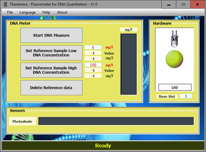
Fluorometer to measure the concentration of DNA
The measurement is based on fluorescence dye molecules acquire, When you bind to nucleic acid molecules. Adding to the sample, a known quantity of dye and measuring the intensity of fluorescence can be traced to the concentration of nucleic acids present in the sample.
The prototype of dye molecule is ethidium bromide, but harmful, being a carcinogen. Recently they have become available to other agents acting in the same way, but they're safer than ethidium bromide. In our case it was adopted the dye known commercially as MidoriGreen.
Authors
Ana Rodriguez (MUSE)
Lodovico Appetite (Theremino)
Documentation (the same that you download with the application):
URTheremino_DNAMeter_ENG.pdf
URTheremino_DNAMeter_ITA.pdf
Downloads on Theremino DNA Meter – Versione 1.1
Theremino_DnaMeter_V 1.1
Theremino_DnaMeter_V 1.1 _WithSources (version for programmers)
For all systems from Windows XP to Windows 10, both 32 which in 64 bit (Linux and OSX with Wine)
The DnaMeter has been enhanced with version 1.2, follow the developments on the site physicsopenlab:
http://physicsopenlab.org/2016/04/15/fluorimetro-diy-per-misure-di-dna
Theremino Balance
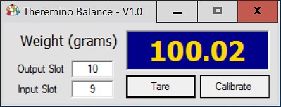
This application reads the raw value for a Slot and make the basic operation of a precision balance (Tara and calibration).
The tainted value, read input slot, is processed. An average Adaptive stabilizes the readings, then apply the tare and calibration. Finally the value, converted to grams, is displayed and written output Slot, ready to be used by other applications on the system.
The whole processing is ’ in a few lines, in the main Form, so it is easy to make changes as, for example,, Add imperial units.
– – – – – – – –
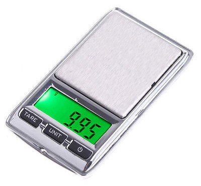 We tried reading a load cell derived from scales that can be purchased for a few dollars on eBay. The load cell has been linked directly to Theremino Adc24 and the measured value is very stable and accurate result. So that we can measure perfectly even hundredths of a gram, even if the scale used was not of great quality and read only the tenths.
To see how to connect the load cells, read the document you download from this page:
HTTPS://www.theremino.com/hardware/inputs/sensors#loadcell
– – – – – – –
Download Theremino Balance-Version 1.1
Theremino_Balance_V1.1
Theremino_Balance_V1.1_WithSources
For all systems from Windows XP to Windows 10, both 32 which in 64 bit (Linux and OSX with Wine)
Theremino BalanceReader


This application does not read any type of load cell through the slots, like the previous Theremino Balance, but law commercial scales, connected to PC serial port.
Currently, the application reads the scales "HS-N" produced by "FUZHOU HENGZHAN ELECTRONIC co., LTD". Are precise and economic scales, great for small laboratories and have a very simple transmission protocol.
Other patterns of scales, electronic gauges and comparators, have similar protocols. This application can then be a basis, from which to connect other measuring instruments, the system Theremino. In this example, the value read from the scale (in grams), is constantly being written into the Slot 1.
Change this application is quite easy. Reading and decoding data, incoming Com Port (RS232 or RS485), are concentrated, in little more than a page of code, in the main Form.
– – – – – – –
Download Theremino BalanceReader – version 1.1
Theremino_BalanceReader_V1.1_WithSources
For all systems from Windows XP to Windows 10, both 32 which in 64 bit (Linux and OSX with Wine)
Theremino PointFollower

This application reads the image from a camera and find the Centre of gravity of a bright spot.
This mode of operation has been prepared for telescopes, to center the mock star produced by a laser. But the same principle can be used for many applications to process control, in industrial production and in scientific applications.
Theremino PointFollower is the basic application to read and process a video signal.
To create new applications we recommend copy this application, change name and follow these instructions: downloads/notes-on-software # advices
– – – – – – –
Principle of operation
A correction value is sent to the two slots, whose values are horizontal and vertical shift. When the point is perfectly centered slots contain the value 500. Adjusting tracking parameters, two servo motors can be controlled multiturn.
For information on search engines read here: hardware/outputs/motors
– – – – – – –
Notes for versions
Version 1.4 – Fixed a bug, that happened with some webcams, on Windows7 64 bit.
Version 1.5 – Delete the flashes on startup.
Version 1.6 – Deleted the files CustomControlLib and DirectShow, now I'm inside the application itself.
Version 1.7 – Fixed a bug that prevented the opening with some webcams.
Download Theremino PointFollower – version 1.7
Theremino_PointFollower_V 1.7
1.7 Theremino_PointFollower_V _WithSources (version for programmers)
Theremino_PointFollower_V 1.1 _OdtDocs (OpenOffice documentation for translators)
For all systems from Windows XP to Windows 10, both 32 which in 64 bit (Linux and OSX with Wine)
Theremino Dvr

This application is just an example, a skeleton on which to build, don't expect the usual quality and comfort of the other applications of the system Theremino.
Implement key parts (audio, WebCam settings, video compression, resolution and frame rate settings, etc ...) but there are no parts that need to save the settings and restore them when you restart the application, and other functions that could be comfortable.
Download Theremino video recorder – Version 0.2
Theremino_VideoRecorder_V0.2_WithSources
For all systems from Windows XP to Windows 10, both 32 which in 64 bit (Linux and OSX with Wine)
Theremino VideoInspector
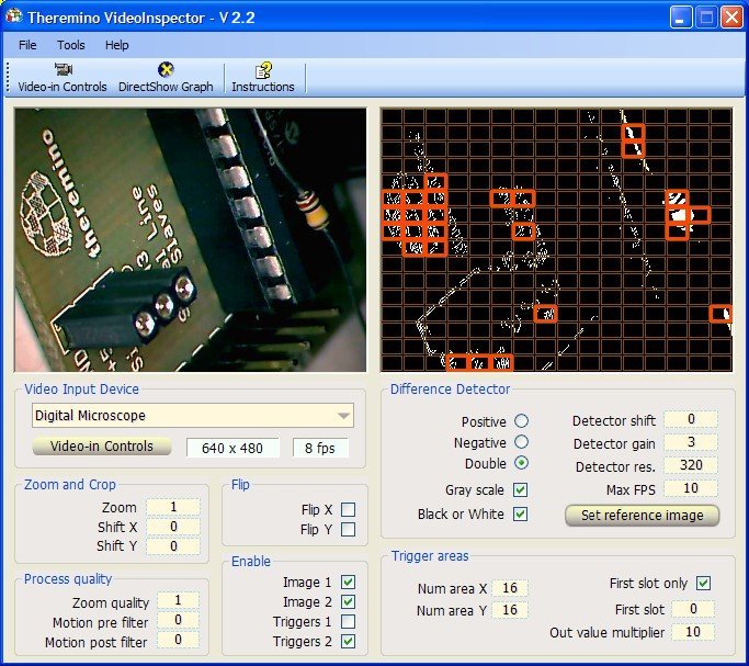
The Video Inspector is designed to locate missing components on printed circuit boards, During testing of the modules of the system Theremino.
The functions of this application are:
- Reading of the video signal.
- Signal conditioning.
- Extraction of differences from a comparison picture.
- Writing values of differences in “Slot”(1) of the Theremino System.
(1) Video Inspector is a modular component system Theremino then interacts with other components in the system through the slots.
Visual inspection of PCB
Functional electrical control does not highlight any errors, for example, the lack of protection diode on the power supply, so a Visual inspection is always required. Unfortunately human traders after a few hundred modules begin to function well and tend to “complain”. This program does not replace the operator but provides alarm indication and allows you to work much faster, without tiring.
For best results it is recommended to use high resolution cameras, strong lighting and very well spread and to arrange a precise positioning mechanism of the PCB.
Similar applications
Not only the control PCBs but many automation applications can use usefully to this application. Image reading and recognition are implemented carefully and optimized. Applications requiring additional functions might lean on this basis and add only the missing parts.
– – – – – – –
Notes for versions
Version 1.9 – Fixed a bug, that happened with some webcams, on Windows7 64 bit.
Version 2.0 – Delete the flashes on startup.
Version 2.1 – Fixed “First Slot” not being reloaded at boot.
Each time you press the button “Load reference image” the reference image is also written to file.
Each time the file “ReferenceImage.png” is reloaded (If it exists and if it is compatible with the chosen resolution)
Version 2.2 – Changes the name of the button to “Load reference image” to “Set reference image”, which is more appropriate.
Aligned instruction files and images for the variations introduced in versions 2.1 and 2.2
Version 2.3 – Deleted the files CustomControlLib and DirectShow, now I'm inside the application itself.
Version 2.4 – Fixed a bug that prevented the opening with some webcams.
Download VideoInspector Theremino – Version 2.4
2.4 Theremino_VideoInspector_V
2.4 Theremino_VideoInspector_V _WithSources
For all systems from Windows XP to Windows 10, both 32 which in 64 bit (Linux and OSX with Wine)
Theremino Way VideoInput

The Video Input is designed to detect changes in video images (movement detection) from a camera.
The uses are manifold, perimeter surveillance to burglar alarms, from access control to the revelation of the passage of animals.
Even the classic industrial applications (for example, point out the lack of caps on cans) can use the functions of this application or the earlier application “Video Inspector”
The ability to describe areas of interest, also overlays, allows you to specify different types of alarm and concern for many areas of the image and to exclude the zone nonsignificant or “noisy” as the curtains that move air travel.
Many applications can coexist on the same computer way VideoInput, each with its own folder its parameters and its fully independent camera.
The functions of this application are:
- Reading of the video signal
- Signal conditioning
- Extraction of movements
- Writing values to difference in the "Slot"(1) of the Theremino System
(1) Video Input is a modular component system Theremino then interacts with other components in the system through the slots.
Similar applications
Many automation applications can use usefully to this application. Reading images and gesture recognition are implemented carefully and optimized. Applications requiring additional functions might lean on this basis and add only the missing parts.
– – – – – – –
Notes for versionsVersion 1.9 – Fixed a bug, that happened with some webcams, on Windows7 64 bit. Version 2.0 – Delete the flashes on startup.
Version 2.1 – Deleted the files CustomControlLib and DirectShow, now I'm inside the application itself.
Version 2.2 – Fixed a bug that prevented the opening with some webcams.
Download Theremino way VideoInput – Version 2.2
Theremino_VideoInput_V 2.2
Theremino_VideoInput_V 2.2 _WithSources
For all systems from Windows XP to Windows 10, both 32 which in 64 bit (Linux and OSX with Wine)
Theremino MicroViewer

This application allows you to get the most out of every Webcam or Digital Microscope. Of course if you are starting with a device with 640 x 480 native pixels (like in this picture) the quality will be limited.
When you buy a device, make sure that is at least HD 720 p (1280 x 720) or even better Full-HD 1080 p (1920 x 1080) And be careful not to get fooled by the many mega-pixels that are often declared. The mega pixels interpolated from the software are always much more real hardware resolution, but you have to spot the true resolution, that unfortunately often is the usual miserable 640 x 480.
This software was created to copy slides with a “OVT Scanner”, and could still be used for that use, but was expanded with the zoom functions that allow you to use it as a microscope and obtain the maximum magnification and quality possible from each WebCam. For use as a slide scanner read the instructions included with the program, contain many useful tips.
Use your WebCam as a microscope
Many Webcams, even inexpensive, have the removable lens to focus up close. With some of them, by unscrewing the lens, You can focus on a few millimeters, and you get a great microscope. If you are starting with an HD WebCam or FullHD results will be even better.
– – – – – – –
Version 1.2 -Fixed some bugs. Primarily an error in sending application crash opening with some WebCam models.
Version 1.3 – Control of the parameters of the WebCam is much improved, now work even more exotic parameters like fire (for webcams that have).
Version 1.4 – Fixed a bug that could, in rare cases, cause of application.
Version 1.5 – Fixed a bug, that happened with some webcams, on Windows7 64 bit.
Version 1.6 – Insured working even on PC, where you are unable to make the CPU tests.
Version 1.8 – Added the ability to zoom in on the image with double click on the image.
Version 1.9 – Fixed a bug that, on some computers, could not save the images with "Double density".
Version 2.0 – Added a Slot of automation, to save the image to file. The image will be written when the Slots exceeds the value 500. To save a new picture, you must "rearm" mechanism, bringing back the slot zero for a few milliseconds.
Version 2.1 – Additional minor corrections, including the JPEG quality that did not work well.
Version 2.2 – Added the cross cursor to center the holes and make the zero piece with ThereminoCNC.
Version 2.3 – The version 2.2 no longer worked on 64 bit (because it was compiled with “Anycpu” instead that “X 86”), Now this is fixed.
Version 2.4 – Delete the flashes on startup.
Version 2.6 – Deleted the files CustomControlLib and DirectShow, now I'm inside the application itself. Added the ability to double click on the image and take it full screen. The mouse cursor disappears after 2 seconds the picture in full screen. Delete a mistake sending crash zoom application other than one and closed while minimized.
Version 2.7 – Fixed a bug that prevented the opening with some webcams.
Download Theremino MicroViewer – Version 2.7
Theremino_MicroViewer_V 2.7
2.7 Theremino_MicroViewer_V _WithSources (version for programmers)
For all systems from Windows XP to Windows 10, both 32 which in 64 bit (Linux and OSX with Wine)
Theremino MicroVideo
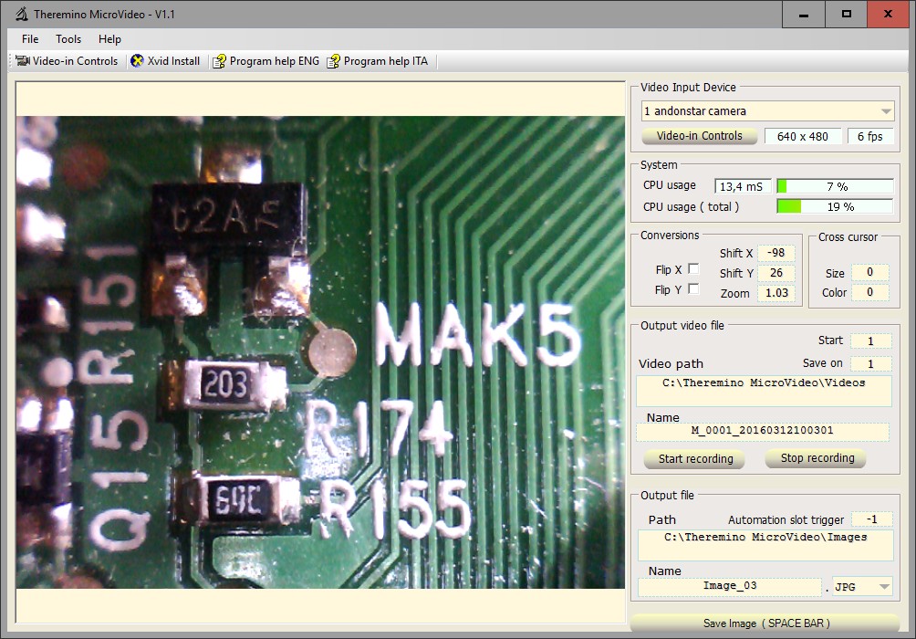
This application is very similar to MicroViewer, but it can also record video. It can also start recording and stop her, using external commands (through the slots).
This is not one of the usual applications that, When you press “Start”, It takes two seconds to start recording, but a real precision scientific instrument.
With “Start” recording starts instantaneously and with “Stop” instantly stops. Then you can, for example,, place it in a machine tool, and document rare events, that would otherwise be difficult to grasp. Or film the passage of animals that are moving fast. Or even perform scientific experiments, that require a precise correspondence between the frames and the real time.
These amazing features were developed by Nick, a Chinese engineer highly arranged. Without him we wouldn't have accomplished this application.
The recording format XVID
The recording files are compressed in XVID format, the only format that allows a precise control of timing of individual frames.
If XVID is not already in the system, You can easily install, with the button “XVID Install”, located at the top of the application.
Recording command slots
In the boxes “Start” and “Save on” you set a number of slots. This number can be “-1”, If you want to disable, or from 0 to 999 to indicate which Slots use.
If you keep them both with the same number of slots, for example, “1”, When the slot value exceeds the 500 starts recording. Then, When it drops below 500, the recording stops.
The application is being completed and right now we don't know why there are two boxes, likely to become one. If you want more detailed information, or you have some problems to be solved, write directly to Nick who wrote the recording software and knows the details.
Nick = goodluckyuming@126.com
(You can write either in English or Italian, He translates everything into Chinese)
– – – – – – –
Version 1.1 – This is the first published version, still has some flaws but you can already use.
Versions 1.3, 1.4 – Improved stability.
Versions 1.5, 1.6 – Improved stability and added the ability to control Zoom with a Slot.
Download Theremino MicroVideo – Version 1.6
Theremino_MicroVideo_V1.6
Theremino_MicroVideo_V1.6_WithSources (version for programmers)
For all systems from Windows XP to Windows 10, both 32 which in 64 bit (Linux and OSX with Wine)
Theremino ImgToGcode

The RobotArm and other automation applications can use usefully to this small utility that converts an image into Gcode.
The size in millimeters of Gcode generated are the same as the image comes from (editable photo editing programs)
– – – – – –
ImgToGcode should be completed in the following parts:
The two functions of skeletonization algorithm “Rosenfeld” should be reduced one but for now we keep them separated because in some cases goes better than the first, and in others the second (mainly on the edges of the image) To avoid errors on the edges it is always best to use images with at least one pixel white border all around.
Resize button which now reduces the current size of the window should be replaced with the ability to set the pixel dimensions and final in millimeters.
– – – – – –
ImgToGcode is used so
- LoadImage – An image composed of STROKES (not a landscape)
- Rosenfeld – To get the contours
- Vectorize – To produce the GCode (associated program files and view them with GC)
If the files are not associated with a GC visualization program, Windows emits an error. To avoid this error, associate them with Notepad or an appropriate viewer, for example Metacut. However, even with this error, the file is generated and the GC is located in the folder of source images.
Download Theremino ImgToGcode – Version 1.5
Theremino_ImgToGcode_V 1.5
Theremino_ImgToGcode_V 1.5 _WithSources
For all systems from Windows XP to Windows 10, both 32 which in 64 bit (Linux and OSX with Wine)
– – – – – –
Theremino ImgToGcode – Version 1.9
This new version has so many new features that some might find it difficult to use it. We have therefore decided not to replace the previous version.

If you use the settings of this picture, the new version behaves approximately as the previous one and generates files suitable for Arm Theremino.
With the new settings you can determine the resolution, output size, and the depth of engraving, in connection with the gray levels in the image. With this version you can generate G-Codes for 3-axis milling machine. You can make low reliefs, printed circuit boards, engravings, plaques and machine parts.
Small instructions from top to bottom:
- Load image – Loads a new image. In the "media" folder and in its subfolders contains many images per section and test images. Go up one level to "medium" and descend into subfolders.
- Reload image -Reload the image eliminating the eventual skeletonization.
- Original res. Original image resolution – which it Informs (width in pixels)
- Resolution – Establishes the resolution of the image that is used in the program (width in pixels). Reduce the resolution to generate faster machining. Or you increase resolution, to improve the quality, at the expense of processing time.
- Blur – Turn the transitions between black and white, in an area with all intermediate levels of gray. A proper setting of this parameter, in conjunction with the Threshold and WeightedDown, can generate bas-reliefs and other interesting effects.
- Rosenfeld – Two slightly different types of "scheletrizzazione". Stroke images are turned into single lines and you get a big reduction in machining time finals. The types "1? and "2? are almost identical, have only minor differences on the edges. When using Rosenfeld is right use the Vectorization of type "Follow borders" and disable "Wighted down"
- Threshold – The level beyond which the image is considered "white". The maximum value is 254 and it means taking into account all levels of gray. Lowering this value, you will lose all clear details and processing becomes more rapid.
- Weighted down – If you enable this check box the working height (Z axis) changes from gray levels in the image. Going from white to black, the level will vary from zero to the value in millimeters, established from "Down". If this check box is disabled, then the level "Down" is used for all non-white areas (darker than Threshold)
- Parallel vertical – Working with vertical lines. Do you use for images with large areas and for BAS, in conjunction with "Blur", "Weighted down" and "Threshold" very high (normally 254).
- Parallel horizzontal – Working with horizontal stripes. Do you use for images with large areas and for BAS, in conjunction with "Blur", "Weighted down" and "Threshold" very high (normally 254).
- Follow borders – Process that follows the contours of the dark areas (Below Threshold). It is mainly used for images with single lines (I have been scheletrizzate with Rosenfeld). This type of processing is the best to generate the GCodes to RobotArm, but it is also usable with the cutter, to make printed circuit boards. Generally if you use FollowBorders you turn "Weighted down".
- Width (mm) – Working width in millimetres.
- Height (mm) – Height in millimeters of the working.
- Use image aspect – If enabled, maintains a constant ratio of width to height.
- Use image size – If enabled, the size of production are established, print size, the image itself.
- Up (mm) – High level of processing. Set it high enough to prevent the bit touches the workpiece material, during the quick movements. If you overdo it you increase the working time.
- Down (mm) – Low level of processing. Set it according to the desired engraving depth. Sure that the cutter should be able to cut sideways, for all the depth of engraving. If you overdo the cutter may break. The software does not monitor such errors. So before you start the cutter, check with a suitable program, for example, Metacut.
- Tool size (mm) – The cutter diameter. For precision machining using small diameter cutters (even up to 0.3 mm) and increasing the "Resolution". Use small diameter cutters greatly increases the processing time and increases the risk of breakage.
- Feed ((mm/m)) – Forward speed during processing. With tiny cutters is well lower it, to reduce the risk of breakage.
- Rapids ((mm/m)) – Forward speed during quick movements. You should set a value equal to the maximum speed of the machine. With lower values it slows down processing. With too high values, the machine itself limits the speed and the working time is calculated wrong.
The GCode can be explored with Wordpad or Notepad. In the first few rows there is a line that starts with MCUSTOCK. In this line you can read machining dimensions in millimeters. At the end of a data block is GCode, with the approximate time of processing.
When you press "Create GCode" Windows may report that the files are not associated with a display program. To avoid this message, bind the GCode (GC file) a Notepad, WordPad or better in a special viewer program for GCode (for example Theremino CNC).
Anyway, Although the error message is issued, GC file is always raised and is located in the folder of images, next to the image from which it was generated.


If you install a suitable program, You can see the workings, otherwise they imagine. A suitable program to see Gcode files could also be ThereminoCNC (which however has a rather simple three-dimensional display).
– – – – – –
Notes for versions
Version 1.9 – Now the app opens without errors, even without image. Moreover, if the image has the right path, find by name, in the sample images folder.
Version 2.0 – Improved the timing and added the button “View vectorized” which makes using the application more convenient.
Download Theremino ImgToGcode – version 2.0
Theremino_ImgToGcode_V2.0
Theremino_ImgToGcode_V2.0_WithSources
For all systems from Windows XP to Windows 10, both 32 which in 64 bit (Linux and OSX with Wine)
Theremino ImgGreyscaleToGcode
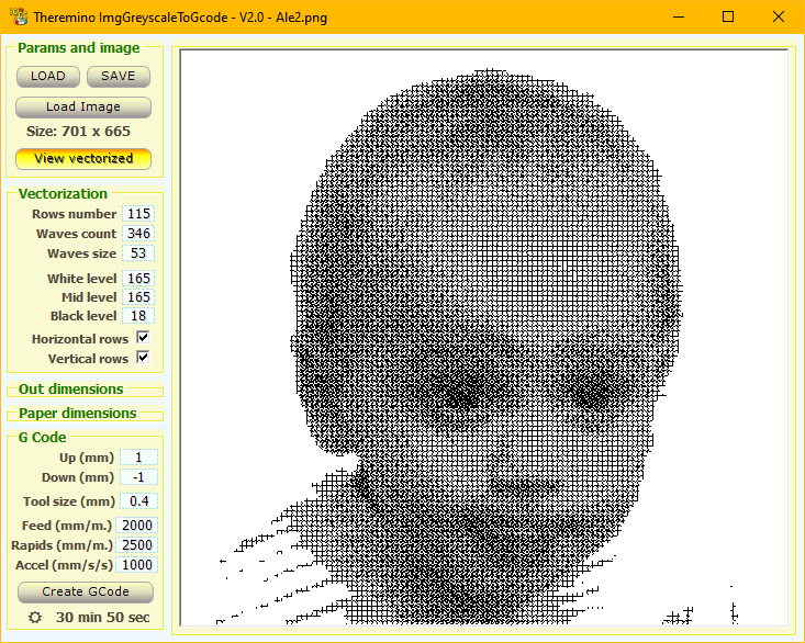
This application can simulate grayscale with a tool that could not, for example a cutter or an ink pen.
The commands are simple to use because you immediately see the effect of each variation. Time is shown below and you should try to keep it short.
When you press "Create GCode" Windows may report that the files are not associated with a display program. To avoid this message, bind the GCode (GC file) a Notepad, WordPad or better in a special viewer program for GCode (for example Theremino CNC).
Anyway, Although the error message is issued, GC file is always raised and is located in the folder of images, next to the image from which it was generated.
– – – – –
Theremino ImgGreyscaleToGcode Download - Version 2.0
Theremino_ImgGreyscaleToGcode_V2.0
Theremino_ImgGreyscaleToGcode_V2.0_WithSources
For all systems from Windows XP to Windows 10, both 32 which in 64 bit (Linux and OSX with Wine)
Theremino GcodeToImage

This application transforms a vector file (for now only the GCODE but also in the future WMF and DXF) in an image (BITMAPS, JPEG, PNG, TIFF etc..)
Converting vectors in the image (Vector to Raster), is required for machines that can not read, vector images (Laser Cutter, Engraving and similar machines). There are programs that do these conversions, but they are difficult to use, lenses to install and expensive.
– – – – – – –
Notes for versions
Version 0.1 – In this first version read the GCode is rough and most likely some GCode will be misinterpreted. Some pious soul should replace reading the GCode to Theremino CNC, but unfortunately this is not an easy task that only a good programmer could do. With GCode simple this app works well and can be very useful.
Download Theremino GcodeToImage – version 0.1
Theremino_GcodeToImage_V 0.1
Theremino_GcodeToImage_V 0.1 _WithSources
For all systems from Windows XP to Windows 10, both 32 which in 64 bit (Linux and OSX with Wine)
Theremino ImgToVectors
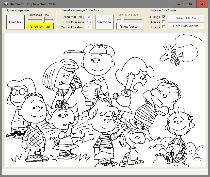
This application transforms the images (JPG, PNG and the like) in vectors. And’ a difficult task and this is one of the few free utilities that do (as an alternative you could use WinTopo but is not Open Source).
From version 1.8 We introduced the ability to save the vector images in Fidocad.
Short instructions
The commands are few and it is quite easy to use them. It is recommended to do various tests to find the best combination of parameters that, unfortunately, change much from one image to another.
- Load file – Allows you to upload a new image to be converted.
- Threshold – Typically goes lowered until you have fine lines but without the lines lose continuity and creating breaks.
- Show bitmap – Press this button to see the original image.
- Area min – Increasing small details are excluded to minimize and a cleaner output file. After editing you have to press “Vectorize” otherwise the buttons “Save” are disabled.
- Error tolerance – Increasing it will produce lines with less intermediate points, to minimize and a cleaner output file. After editing you have to press “Vectorize” otherwise the buttons “Save” are disabled.
- Corner threshold – Determines the maximum angle above which the curves are broken. We recommend that you keep it around to one. After editing you have to press “Vectorize” otherwise the buttons “Save” are disabled.
- Vectorize – Transforms from image to vectors.
- Size – Determines the pixel size of the image output. We recommend that you keep it as low as possible, Depending on the required quality. FidoCad very large images may become difficult to treat and FidoCad did not then functions to resize them.
- Show vector – Press view the vectorized image. It is used only if you have first pressed “Show bitmap”, otherwise it comes down automatically with every conversion.
- Fillings – Manufactures and view areas filled. By enabling this check FidoCad files contain areas converted to primitive FidoCad Spline.
- Traces – Manufactures and view outline. This certification does not produce differences on files FidoCad.
- Points – Manufactures and view areas filled. This certification does not produce differences on files FidoCad.
- Save EMF file – Produces an EMF vector (Enhanced Meta File – the successor of Windows Meta File).
- Save FidoCad file – Produces a vector of type FCD (Fidocad or FidoCadJ).
Important not to exaggerate the size of the image (in pixels) and with its complexity, otherwise the conversion time might grow out of proportion. You are also advised to keep down the cursor “Size”, not to produce EMF images or FidoCad files too large.
Recommendations for areas of FidoCad
The areas are transparent and are all grey. In this way it is possible to see them even when they are superimposed. And then you can select one by one and recolored by manually.
The areas are converted into primitive FidoCad Spline that has a limit to the number of points for a single zone. So if the area is large and complex ’ happens that he loses a part. This problem was not heard when you draw by hand but starting from images happens easily.
A small reduction in the number of points you can get by increasing “Error tolerance” but this also leads to a deterioration of the edges of ’ area. For best results l ’ only viable option is to retouch the picture with a paint program and facilitate the conversion. Use extra caution at the edges of areas that connect to other objects, for example the line of horizon ’. Separate them with small interruptions in a logical way and close all areas affecting.
You can find other tips and examples in this article:
http://www.electroyou.it/theremino/wiki/un-regalo-di-capodanno-per-gli-amanti-di-fidocad
– – – – – – –
Notes for versions
– Version 1.8 –
– In this release we introduced the ability to create FidoCad file (extension to FCD).
– The controls are arranged in a more ordered.
– Conversion functions have improved and most of the code is ready for version 1.9 that will produce FidoCad files even with areas that will be colored with the editor of FidoCad.
– Version 2.0 –
– In this release we've added the ability to convert splines in primitive areas FidoCad.
– – – – – – –
Download Theremino ImgToVectors – Version 2.0
Theremino_ImgToVectors_V 2.0
Theremino_ImgToVectors_V _WithSources 2.0
For all systems from Windows XP to Windows 10, both 32 which in 64 bit (Linux and OSX with Wine)
Theremino Pad

This application moves the mouse cursor on the screen, in a location determined by the value of two slots.
An interesting development of this application, will be to read four slots, connected to four CapsSensor, with the antennas on all four sides of a rectangle. This will create a “PAD” (as the floor mats in notebooks) He also feels the vertical position of the finger. The ultimate goal is to make it work behind the glass of shop Windows. Very thick glasses and are currently working in those conditions would be the only technology. There are commercial devices, but they cost a lot and with thick glasses don't work well.
– – – – – – –
Download Theremino Pad – Version 1.3
Theremino_Pad_V 1.3
Theremino_Pad_V 1.3 _WithSources
For all systems from Windows XP to Windows 10, both 32 which in 64 bit (Linux and OSX with Wine)
Theremino ReleSequencer
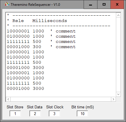
With this small application you can create sequences to control relays, or generic output signals with which to drive all sorts of on/off type actuators.
Exit signs go up three slots connected to tabs Relay Switcher. Each card pilots up to eight relays and tabs can be connected in cascade to drive a large number of relays (or generic outputs).
The special feature of this solution is to be able to drive a large number of outputs, even far away, using only three output pins of a Master, or an Arduino, or NetModule.
Instructions for writing the sequence
The outputs are switched all at once when the line.
On the left side of each line you use zeros to indicate a relay off and one to indicate a relay on. The number of zeros and ones is the number of relays to fly, in this picture are eight but you can grow at will.
The second issue of each line are the milliseconds to duration. So if you write 1000 the line will run for a second before moving on to the next line.
In the right part, After all & #8217; single quote, You can write comments.
Instructions for slots and the Bit time
The three Slots below must match the signal board relay Switcher inputs.
The Bit time is the duration of each bit serial data transmission. Usually this time wrong varied from 10 mS, but you could try to reduce it if you wanted to fly a large number of relays. Beware though that you might have errors in transmission. Probably, to be on the safe side, If the relays are not more than 16 or 32, It would be better to increase it to 20 or 30 mS. The total time of transmission are these milliseconds multiplied by the number of relays. So if you fly, for example,, 16 Relay and set a time of 20 mS, the minimum time required to switch from one line to the following will be 320 milliseconds. That is a third of a second.
Download Theremino ReleSequencer – Version 1.0
Theremino_ReleSequencer_V 1.0
Theremino_ReleSequencer_V 1.0 _WithSources
For all systems from Windows XP to Windows 10, both 32 which in 64 bit (Linux and OSX with Wine)
Theremino DopplerMeter
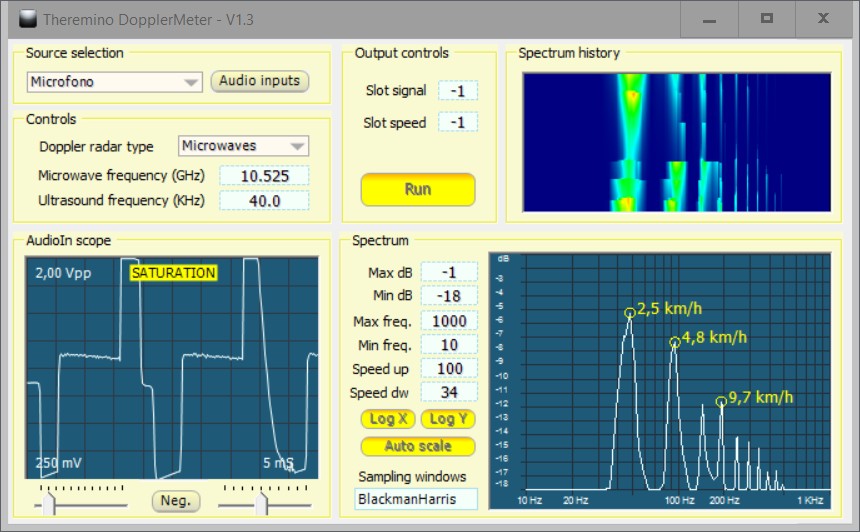
This application measures speed of moving objects, microwave or Ultrasonic sensors.
Fields of application
- Detection of people and animals (car alarms, turn on lights, open doors, taking photographs)
- Measure the speed of birds, drones, missiles and airplanes.
- Measuring the speed of cars, bicycles, skiers, paratroopers, athletes, etc…
- Measure the falling speed and density of rain, hail and snow.
For meteorology (rain, hail and snow) the spectrum analysis provides:
- The average velocity of the particles in the fall (the highest peak)
- The spectrum of speed and therefore particle diameters, for rain and hail
- The spectrum of density, for snowflakes
Approximate speed of falling due to some weather phenomena
- Speed of raindrops
- Diameter 6 mm: 36 Km/h (10 m/s)
- Diameter 5 mm: 32 Km/h (9 m/s)
- Diameter 0.5 mm: 7 Km/h (2 m/s)
- Speed of hailstones
- Diameter 60 mm: 126 Km/h (35 m/s)
- Diameter 40 mm: 100 Km/h (28 m/s)
- Diameter 20 mm: 72 Km/h (20 m/s)
- Diameter 10 mm: 54 Km/h (15 m/s)
- Diameter 5 mm: 36 Km/h (10 m/s)
- Snowflakes dry speed
- Great flakes: 10 Km/h (3 m/s)
- Medium flakes: 7 Km/h (2 m/s)
- -Small flakes: 2 Km/h (0.6 m/s)
- Wet snowflakes speed
- Great flakes: 15 Km/h (4.1 m/s)
- -Small flakes: 5 Km/h (1.4 m/s)
Types of analysis and sensors
By means of the signal spectrum analysis are obtained at the same time the speed of all moving objects. This type of operation does not let himself be fooled, the movements of multiple objects, as portable devices with a single display.
Microwave radars can be found on eBay for a few euros and ultrasonic ones are constructable with normal capsules 40 KHz.
Ultrasonic sensors are just as expensive than microwave, but inferior as performance. Also do not go through the plastic, that is a handy weather protection. So for now we designed only with microwave sensors.
To build a simple and cheap microwave doppler radar reading here:
https://www.theremino.com/hardware/adapters#doppler
– – – – – – –
Download Theremino DopplerMeter – Version 1.5
Theremino_DopplerMeter_V1.5
Theremino_DopplerMeter_V1.5_WithSources
For all systems from Windows XP to Windows 10, both 32 which in 64 bit (Linux and OSX with Wine)
Theremino WiFi

This application measures the intensity of WiFi signals and shows the characteristics of the networks.
By observing the intensity of the signals and the channels used by other networks, you can identify the best channel to use for your access point.
By choosing the display of the next image, that shows the trend of the signals in time, It can also route antennas to improve ties.
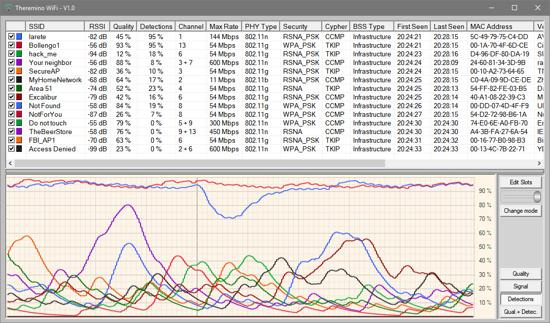
The networks of these images contain little realistic data, They are created by the application itself
to facilitate testing (to create them you build in debug and press CTRL-SHIFT and CTRL-ALT).
ATTENTION : This application is designed to adjust the antennas and to explore the networks with an answer as fast as possible. During its operation the continuous scanning of WiFi frequencies disturbs and greatly slows down the data traffic on the device where it is running. So do not keep it open during normal use of the network. Use it only during the measurements and then close it.
– – – – – – –
Send measured values to Slot
Pressing “Edit Slots” It opens the configuration file that allows you to send the measured values to the slot of the system Theremino. The intensity values of the signals, the quality of the signals and the frequency with which each signal is detected, They will then be available for other applications of the system. They can then keep under control the networks and also build automation systems For example you might rotate an antenna and locate the position of maximum signal.
In the configuration file you write the names (SSID) networks and affecting the numbers of slots to send the measured value.
– – – – – – –
Notes for versions
Version 1.3
– Fixed an error that happened when opening the application.
– This version also reads channels above the 14 (band 5 GHz).
– – – – – – –
Download in Theremino WiFi – Version 1.3
Theremino_WiFi_V1.3
Theremino_WiFi_V1.3_WithSources
For all systems from Windows XP to Windows 10, both 32 which in 64 bit (Linux and OSX with Wine)
Theremino SignalDecoder
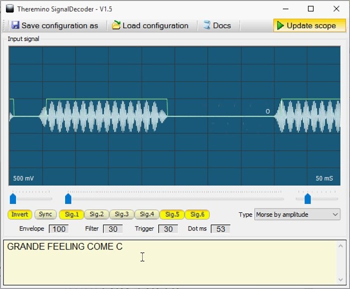 This application decoding radio signals received by Theremino SDR. Morse signals are converted to text, While the coded signals are compared with a mask to eliminate interference and finally converted to numbers and sent to slots. You can then review other applications of the system Theremino, by means of coded radio signals.
Related projects: application Theremino SDR, adapter Upconverter and Active Antenna. For more information read the documentation files that are downloaded with the application Theremino SDR.
These YouTube videos are examples of Morse code decoding:
https://youtu.be/eaK9QHX0VVs
https://youtu.be/xwpt4BjZKYo
https://youtu.be/D6nTDDXkR2U
Morse signals are received mainly in short waves, amateur radio bands. While the signals of remote controls and weather signals are in the bands of 433 and 866 MHz, or from 200 to 350 MHz, for older models.
The types of signals already implemented are:
- Morse code
- Remote control signals with coding Ev1527 to 25 bit
- HT12E coding remote signals to 13 bit
- MM53200-encoded remote signals to 13 bit
- Motorola-encoded remote signals 5026 to 18 bit
- Remote control signals UM3750 encoded in 13 bit
The application Signal Decoder is already prepared to receive signals encoded weather module. For example the “Oregon Scientific”, “La Crosse” and “Auriol”, they send the temperature and pressure every minute. And also for external weather sensors signals for the wind and rain. But These signals are poorly documented, so it will take some time to implement them.
– – – – – – –
Download Theremino SignalDecoder – Version 1.6
Theremino_SignalDecoder_V 1.6
Theremino_SignalDecoder_V 1.6 _WithSources
For all systems from Windows XP to Windows 10, both 32 which in 64 bit (Linux and OSX with Wine)
Theremino SDR
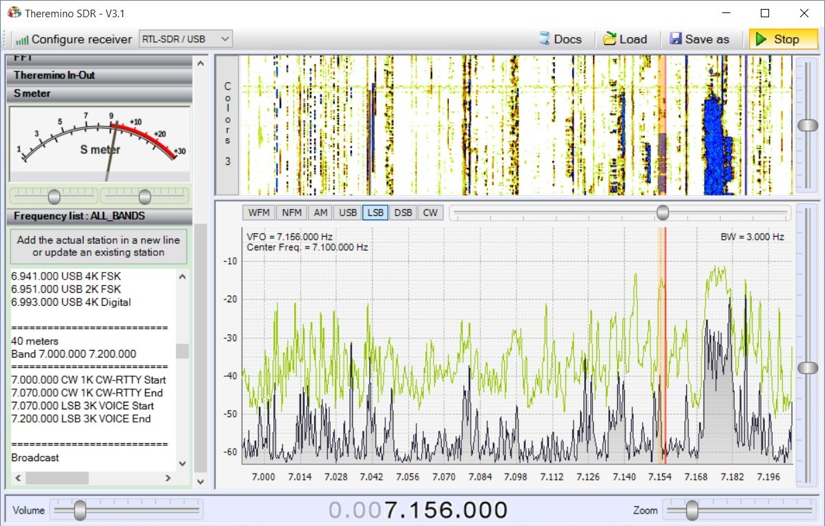
Theremino SDR is a multimode receiver (FM, NFM, Am, SSB and CW), usable also as measuring instrument and Spectrum Analyzer, to develop transmission and reception equipment. Covers all frequencies from long waves (10 KHz) up at ultra-high frequency (1.8 GHz). To work needs little hardware. You spend very little (from a minimum of eight euros to a maximum of a few tens) and you also have the satisfaction of having built your receiver.
With minimal hardware SDR and Theremino from 8 Euro, You can receive:
- Dozens of commercial radio stations in FM, in stereo, with quality comparable to the best FM receivers.
- Coded radio signals. You can decode these signals with the SignalDecoder and send them to the slots of the system Theremino to control other applications of the system.
- The coded signals of transmitters for temperature wind and rain (for example the Oregon Scientific and similar devices).
- Signals from weather satellites “NOAA”, you decode in beautiful color weather images, with the excellent freeware application WXtoImg.
Adding the ActiveAntenna and UpConverter you also receive:
- Hundreds of commercial radio stations in long waves, medium and short, in all the languages of the world and up to incredible distances.
- Communications between radio amateurs of the mythical shortwave bands (160, 80, 40, 20, 17, 15, 12, 11 and 10 meters). At times they feel hundreds of QSOS and it is not uncommon to hear ham radio broadcasting from great distance, also from other continents.
- Communications on pirate gangs (170, 88, 45 and 23 meters, as well as pirated channels of 11 meters)
- Communications in Morse code, decodable with SignalDecoder. Incredibly Morse code is still widely used. At times you can hear dozens of Morse transmissions on all bands.
- RTTY Communications (teletype) and encoded with the strangest codes, also they can be decoded using the special applications.
- Air navigation beacons (Non-Directional Beacons)
- Scientific signals for synchronization of telescopes, atomic time signals based on samples. Meteorological radar signals and signals of the air force (VOLMET).
Interactions with the system Theremino
All applications in the system Theremino may interact with Theremino SDR. The audio signal can be decoded further (for example with Theremino SignalDecoder) and you can receive and send commands through the slots. The interactions include the frequency setting, volume and mode of operation (FM, Am, SSB, CW etc..), and the ability to control other equipment with the received signals.
Related projects:
Application Theremino_SignalDecoder,
Adapter Theremino_UpConverter
Antenna Theremino_ActiveAntenna
Some video with examples of receiving communications between amateur radio operators:
Video with SSB communications on the band of 40 meters
Videos featuring Morse signals, RTTY and SSB on the band of 40 meters
Long examples with which you can test the sound quality. They are largely long distance reception, hundreds to thousands of kilometres. Note also that you listen well all corresponding, not just local ones:
ThereminoSDR_SSB_Signals_1
ThereminoSDR_SSB_Signals_2
ThereminoSDR_SSB_Signals_3
ThereminoSDR_SSB_Signals_4
ThereminoSDR_SSB_Signals_5
Video with examples of Morse code decoding:
https://youtu.be/eaK9QHX0VVs
https://youtu.be/xwpt4BjZKYo
https://youtu.be/D6nTDDXkR2U
Video decode RTTY weather station:
https://www.youtube.com/watch?v=a328_j_SM2M
Images showing the large number of stations receivable:

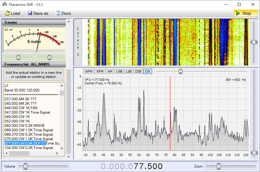
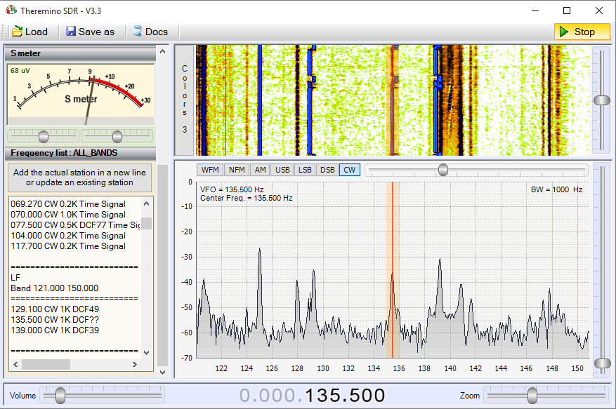
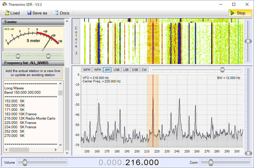
– Band: VLF – Band: LF1 – Band: LF2 – Band: Long Waves
![]()
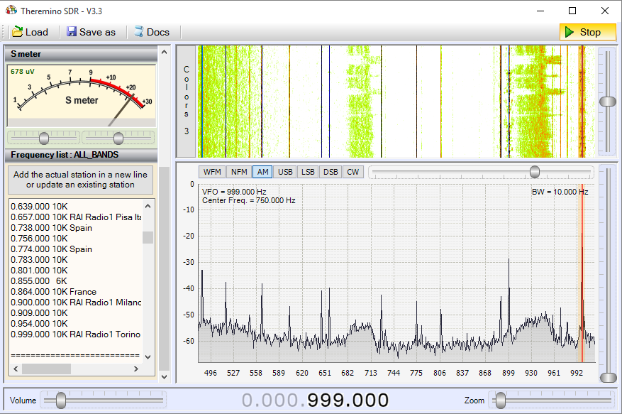
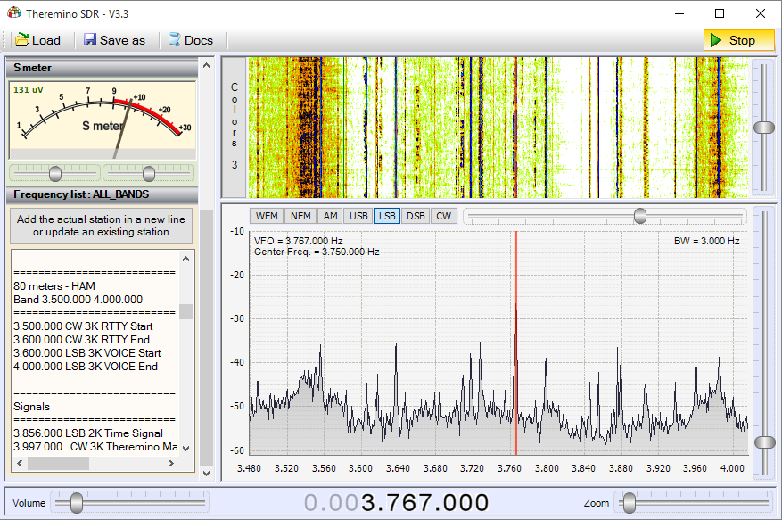
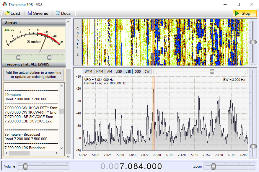
– Band: Beacons – Band: MW – Band: 80 meters – Band: 40 meters
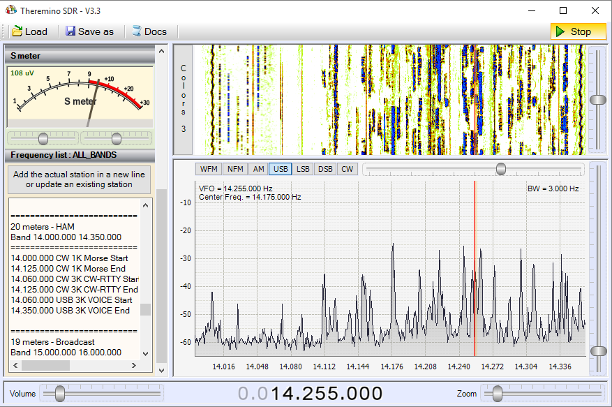
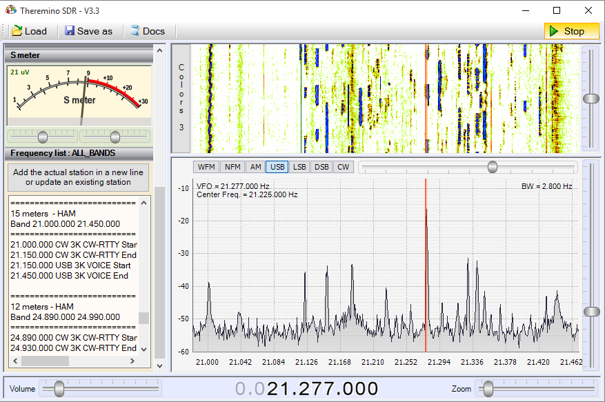
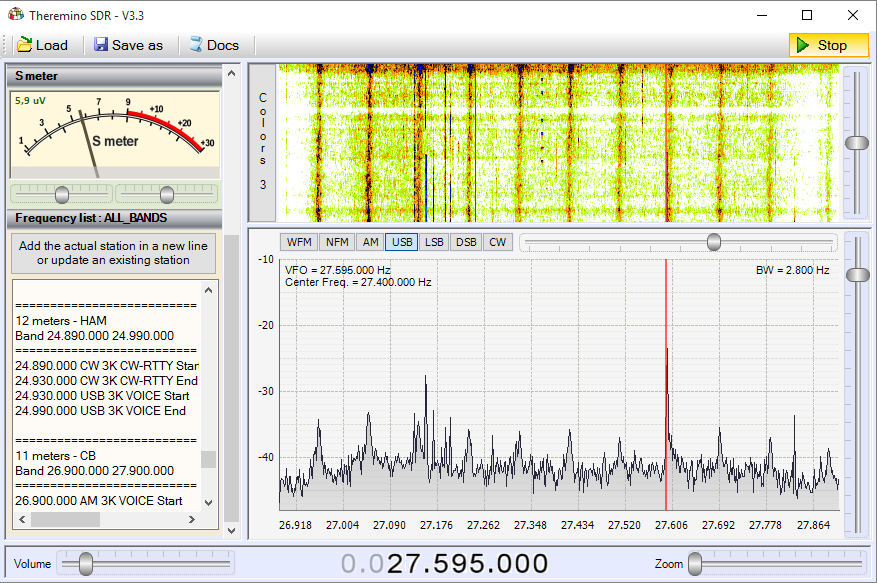
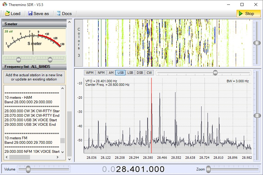
– Band: 20 meters – Band: 15 meters – Band: 11 meters – Band: 10 meters
Click on images to enlarge them.
Images received with the “Theremino UpConverter” and with the “Theremino ActiveAntenna” positioned on a terrace, about 7 meters high, in Northern Italy, in times of good propagation. These are the most interesting bands for radio amateurs and scientific signals, but cover less than 10% receivable frequencies. The remaining 90%, here not visible, is reserved for the Navy, Aviation, Police and commercial stations, with hundreds of transmissions, “broadcast”, that broadcast news and music from around the world.
– – – – – – – – –
Receive shortwave without UpConverter
The version 4.6 has the new box “Sampling mode” in the Panel “Receiver”. Opening it and select “Direct sampling sampling mode = Q” You can enable the “Rtl2832u version 3” to receive shortwave.
You will then receive the frequencies from 500 KHz (and even less) up to 30 MHz without building the Theremino_UpConverter. The feeling is a little’ bottom, the noise a little’ increased and the minimum frequency does not reach the 10 KHz of “Theremino UpConverter”, so no VLF. But also can be a viable and simple alternative to receive shortwave.
The “Rtl2832u V3″ It can also deliver a voltage of 5 volts to power active antennas. If you want to enable this tension should do with Theremino SDR closed. So before launching Theremino SDR you double click on the file “bias_tee_on.bat” located in the folder “_ RTL-SDR _ V3_Notes” / “Bias Tee On Off”.
Careful not to directly connect the Theremino ActiveAntenna at “Rtl-SDR _ V3” that issues 5 Volts. On this page There is a simple pattern to power the Theremino_ActiveAntenna with the 5 volts coming from the “Rtl-SDR _ V3”. Are only three components and you can also adjust the sensitivity.
– – – – – – – – –
In the folder “_ RTL-SDR _ V3_Notes” You can find other information in files:
- “RTL-SDR V3 Notes.txt“, that completes the instructions of Theremino SDR
- “ActiveAntenna_BiasTeeAdapter.jpg“,
Further information on the “Rtl2832u V3”, on this page:
http://www.rtl-sdr.com/buy-rtl-sdr-dvb-t-dongles
– – – – – – – – –
Notes for versions
Version 4.3 – Compiled in Debug mode by mistake. – Slow and inefficient.
Version 4.4 – This version is more efficient, with respect to the 4.3. The load on the processor is reduced to a third. If you minimize the application and use all measures to reduce the consumption, You can get around the 5%, dual core computers. And even less, about quad core. Still need to fix some minor flaws. Does not start with the same “Gang” with which closes and some commands of the “FrequencyList” are not implemented.
Version 4.5
– Replaced Theremino HAL with version 7.0 (the version 6.9 gave errors changing Pin type).
– Improved handling of Mouse. Now work fine even the Mouse with wheel without shots.
Version 4.6-4.7
– Added the possibility to select the “Sampling mode” in the Panel “Receiver”. By selecting “Direct sampling sampling mode = Q” You can enable the RTL2832U Version 3 to receive shortwave, as explained above.
We have updated the version 4.7 with the latest documentation files.
Those who have downloaded earlier can download it again.
Or you can use the documentation files that you download below.
Download the latest documentation
Theremino_SDR_Help_ITA.pdf
Theremino_SDR_Help_ENG.pdf
Zadig_Instructions_ITA.pdf
Zadig_Instructions_ENG.pdf
Download the latest documentation (originals in ODT format)
Theremino_SDR_Help_ITA.odt
Theremino_SDR_Help_ENG.odt
Zadig_Instructions_ITA.odt
Zadig_Instructions_ENG.odt
ATTENTION : Mr. Youssef Tan of SDRSharp (You can find AirSpy website) We wrote that considers the sources of our application too close to his. We do not think that it is so (see pages 25 and 26 of the instructions). But, Since we simple electronics enthusiasts and not copyright experts, We are awaiting the response of legal advisers. Meanwhile, to make something pleasant to Yussef and prove our good faith, We've eliminated tentatively Open Source version.
Download Theremino SDR – Version 4.7
4.7 Theremino_SDR_V (version without sources – read the note above)
For all systems from Windows XP to Windows 10, both 32 which in 64 bit (Linux and OSX with Wine)

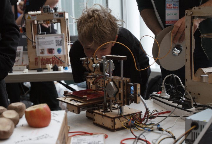